Pioneer VSX-1015-S Service Manual
Audio/video multi-channel receiver
Hide thumbs
Also See for VSX-1015-S:
- Operating instructions manual (78 pages) ,
- Service manual (14 pages)
Table of Contents
Advertisement
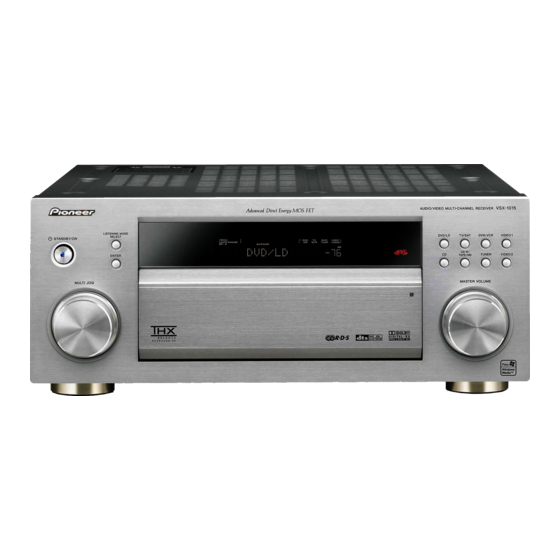
AUDIO/VIDEO MULTI-CHANNEL RECEIVER
VSX-1015-K
VSX-1015-S
THIS MANUAL IS APPLICABLE TO THE FOLLOWING MODEL(S) AND TYPE(S).
Model
Type
VSX-1015-K
HYXJ
VSX-1015-S
HYXJ
*:Alter the wiring of the power-supply block at the primary winding of Power transformer referring to the Line Voltage Selection
described in this Service Manual ("4.18 TRANS 2-2, TRANS 1 and PRIMARY ASSYS").
For details, refer to "Important Check Points for Good Servicing".
PIONEER CORPORATION
PIONEER ELECTRONICS (USA) INC. P.O. Box 1760, Long Beach, CA 90801-1760, U.S.A.
PIONEER EUROPE NV Haven 1087, Keetberglaan 1, 9120 Melsele, Belgium
PIONEER ELECTRONICS ASIACENTRE PTE. LTD. 253 Alexandra Road, #04-01, Singapore 159936
PIONEER CORPORATION 2005
STANDBY/ON
MULTI JOG
Porew Requirement
AC220-230V
AC220-230V
4-1, Meguro 1-chome, Meguro-ku, Tokyo 153-8654, Japan
AUDIO/VIDEO MULTI-CHANNEL RECEIVER
LISTENING MODE
SELECT
DVD/LD
TV/SAT
DVR/VCR
CD-R/
ENTER
CD
TUNER
TAPE/MD
MASTER VOLUME
VSX-1015-K
The voltage can be converted by the
AC240V, *
AC240V, *
VSX-1015TX
VIDEO1
VIDEO2
ORDER NO.
RRV3138
following method.
T-ZZK APR. 2005 printed in Japan
Advertisement
Table of Contents

Related Manuals for Pioneer VSX-1015-S


Summary of Contents for Pioneer VSX-1015-S
- Page 1 PIONEER CORPORATION 4-1, Meguro 1-chome, Meguro-ku, Tokyo 153-8654, Japan PIONEER ELECTRONICS (USA) INC. P.O. Box 1760, Long Beach, CA 90801-1760, U.S.A. PIONEER EUROPE NV Haven 1087, Keetberglaan 1, 9120 Melsele, Belgium PIONEER ELECTRONICS ASIACENTRE PTE. LTD. 253 Alexandra Road, #04-01, Singapore 159936 PIONEER CORPORATION 2005 T-ZZK APR.
-
Page 2: Safety Information
PIONEER Service Manual. A subscription to, or additional copies Also test with plug reversed of, PIONEER Ser vice Manual may be obtained at a (Using AC adapter Earth nominal charge from PIONEER. plug as required) - Page 3 [Important Check Points for Good Servicing] In this manual, procedures that must be performed during repairs are marked with the below symbol. Please be sure to confirm and follow these procedures. 1. Product safety Please conform to product regulations (such as safety and radiation regulations), and maintain a safe servicing environment by following the safety instructions described in this manual.
-
Page 4: Table Of Contents
CONTENTS SAFETY INFORMATION ............................. 2 1. SPECIFICATIONS ............................6 2. EXPLODED VIEWS AND PARTS LIST ......................7 2.1 PACKING ..............................7 2.2 EXTERIOR SECTION..........................8 2.3 CHASSIS SECTION ..........................10 2.4 REAR PANEL SECTION.......................... 12 2.5 HEAT SINK SECTION..........................14 2.6 FRONT PANEL SECTION ........................ - Page 5 8. PANEL FACILITIES ............................133 VSX-1015-K...
-
Page 6: Specifications
1. SPECIFICATIONS Amplifier section AM Tuner Section Continuous Power Output (Stereo) Frequency Range 531 kHz to 1,602 kHz (9 kHz step) ... . . 350 µV/m 150 W + 150 W (DIN 1 kHz, THD 1 %, 6 Ω) Sensitivity (IHF, Loop antenna) . -
Page 7: Exploded Views And Parts List
Battery Cover XZN3140 Operating Instructions (Italian) ARC7572 Label (WEEE) ARW7322 • • • • • • (2) CONTRAST TABLE VSX-1015-K/HYXJ and VSX-1015-S/HYXJ are constructed the same except for the following: VSX-1015-K VSX-1015-S Mark Symbol and Description /HYXJ /HYXJ 16 Packing Case 1015/BY... -
Page 8: Exterior Section
2.2 EXTERIOR SECTION Refer to "2.3 CHASSIS SECTION". Refer to "2.6 FRONT PANEL SECTION". VSX-1015-K... - Page 9 ARW7320 Label (WEEE) ARW7322 Spacer 45B (6 x 7 x 13) AEB7264 Nyron Rivet AEC7408 (2) CONTRAST TABLE VSX-1015-K/HYXJ and VSX-1015-S/HYXJ are constructed the same except for the following: VSX-1015-K VSX-1015-S Mark Symbol and Description /HYXJ /HYXJ Bonnet Case V1B...
-
Page 10: Chassis Section
2.3 CHASSIS SECTION Refer to "2.5 HEATSINK SECTION". Refer to "2.4 REAR PANEL SECTION". VSX-1015-K... - Page 11 (1) CHASSIS SECTION PARTS LIST Mark No. Description Part No. PRIMARY Assy AWX8386 SP/PS Assy AWX8375 NSP 3 DIODE Assy AWX8376 TRANS 2-1 Assy AWX8372 TRANS 2-2 Assy AWX8371 TRANS 1 Assy AWX8383 VH TR Assy AWX8411 NSP 8 TRANS SIDE Assy AWX8417 >...
-
Page 12: Rear Panel Section
2.4 REAR PANEL SECTION POWER AMP IN ( Q ) from POWER PROTECT ( R ) from TRANS SIDE TRANS 2-1 ( X ) VSX-1015-K... - Page 13 AWX8572 FM/AM TUNER Unit AXX7170 > Fuse (FU2501, 2502 : T1.25A) REK1023 • • • • • • (2) CONTRAST TABLE VSX-1015-K/HYXJ and VSX-1015-S/HYXJ are constructed the same except for the following: VSX-1015-K VSX-1015-S Mark Symbol and Description /HYXJ /HYXJ...
-
Page 14: Heat Sink Section
2.5 HEAT SINK SECTION ( B ) from AUDIO CONNECT from ( AB ) SP/PS TRANS 2-1 ( X ) 11 11 from ( L ) MAIN CONTROL VSX-1015-K... - Page 15 (1) HEAT SINK SECTION PARTS LIST Mark No. Description Part No. POWER AMP-L Assy AWX8403 POWER AMP-R Assy AWX8404 POWER AMP IN Assy AWX8405 POWER PROTECT Assy AWX8407 NSP 5 POSI 1 L Assy AWX8536 NSP 6 POSI 1 R Assy AWX8539 Flexible Cable (15P) ADD7473...
-
Page 16: Front Panel Section
2.6 FRONT PANEL SECTION 17 (2/2) (Magnet Holder) from MAIN CONTROL ( L ) 17 (1/2) No. 17 (2/2) Magnet Holder VSX-1015-K... - Page 17 See Contrast table (2) Magnet 35 AMF7007 Standby Button See Contrast table (2) Earth Plate A ANG7484 (2) CONTRAST TABLE VSX-1015-K/HYXJ and VSX-1015-S/HYXJ are constructed the same except for the following: VSX-1015-K VSX-1015-S Mark Symbol and Description /HYXJ /HYXJ 10 Pioneer Badge...
-
Page 18: Block Diagram And Schematic Diagram
3. BLOCK DIAGRAM AND SCHEMATIC DIAGRAM 3.1 BLOCK DIAGRAM 3.1.1 AUDIO SECTION OPTICAL-IN ASSY FRONT-IN CONNECT ASSY FRONT-IN ASSY REAR TOP ASSY L 1/3 L 1/3 MULTI CH I/O ASSY AUDIO CONNECT ASSY VSX-1015-K... - Page 19 DSP ASSY TRANS SIDE HEADPHONE ASSY ASSY REGULATOR ASSY PS/SP ASSY MAIN CONTROL ASSY L 2/3 L 2/3 SAPM01N, SAPM01P SAPM01N, SAPM01P L 2/3 SAPM01N, SAPM01P L 2/3 POWER AMP-L ASSY Y2 (2/2) POWER AMP IN ASSY SAPM01P SAPM01N POWER AMP-R ASSY VSX-1015-K...
-
Page 20: Video And Display Sections
3.1.2 VIDEO and DISPLAY SECTIONS Video Block (1/2) DVD/LD (2/2) IC701 TV/SAT IC731 NJM2595M BU4052BCF (2/2) DVR/VCR (1/2) VIDEO1 (2/2) MONITOR COMPOSITE IC732 (2/2) Selector TK15420M OSD Selector +6 dB AMP (1/2) or BUFFER DVR OUT COMPOSITE A ASSY CN701 CN751 FRONT-IN REGULATOR... - Page 21 Display/SR Block VOLUME ASSY REAR TOP ASSY MULTI JOG ASSY JA951 SR IN DISPLAY V3001 ASSY FL Display JA952 S3251 3002 3251 SR OUT IC3001 PE5403A Display U-COM CN951 14 12 15 16 3001 3201 S3201 11 10 12 9 CN104 Control Signal MAIN...
-
Page 22: Dsp Section
3.1.3 DSP SECTION DSP Block DSP ASSY M 1/2 M 1/2 M 2/2 M 2/2 VSX-1015-K... - Page 23 VSX-1015-K...
-
Page 24: Power Supply Section
3.1.4 POWER SUPPLY SECTION Power Supply Block POWER AMP-L PS/SP ASSY ASSY 4 11 12 CN2004 2001 PRIMARY V+12A ASSY T1001 IC1001 NJM78M56FA W1006 V-12A REG. CN1002 CN2003 D1001 RY1001 CN4501 LIVE CN2002 CN4001 13 12 11 10 NEUTRAL CN1001 4001 D2241 D2242... - Page 25 POWER AMP-R ASSY V+5.6ST V+12A V-12A MULTI CH I/O ASSY DISPLAY V+7A REAR TOP ASSY FM/AM TUNER ASSY UNIT V+5_6U V+9T V-7A V-12A 12 11 10 19 18 CN955 Q951 V+5_6ST CN602 CN601 CN4551 REG. CN4002 CN904 CN903 CN954 CN905 CN4003 V-12A V-12A...
-
Page 26: Overall Wiring Diagram
3.2 OVERALL WIRING DIAGRAM D15A05-100-2651 5/75 VOLUME ASSY *1.5mm (AWX8378) DISPLAY ASSY (AWX8616) mark found on some component parts indicates the importance of the safety factor of the part. Therefore, when replacing, be sure to use parts of identical designation. FRONT-IN CONNECT ADD7473- ASSY (AWX8416) -
Page 27: Multi Jog Assy
D15A05-100-2651 NOTES: • When ordering service parts, be sure to refer to “EXPLODED 5/100 VIEWS and PARTS LIST” or “PCB PARTS LIST”. • The > mark found on some component parts indicates the *1.5mm importance of the safety factor of the part. MULTI JOG ASSY Therefore, when replacing, be sure to use parts of identical (AWX8618) -
Page 28: Multi Ch I/O And Audio Connect Assys
3.3 MULTI CH I/O and AUDIO CONNECT ASSYS MULTI CH I/O ASSY (AWX8681) JA604 R651 R655 R657 IMX25 IMX25 R692 AKB7165 Q651 (2/2) (SW) R660 R659 Q651 (1/2) R654 Q652 R653 (1/2) R658 R652 R656 Q652 (2/2) IMX25 IMX25 (1/3) R631 R633 R637... - Page 29 C601-C604, C631,C632,C641,C642, C611-C614, C651,C652,C661,C662 C621-C624 NOTE AWX8681 VSX-1015 330p,CH 100p,CH 1.RESISTORS Unit: k-kΩ, M-MΩ or Ω unless otherwise noted. Rated power: 1/16W unless otherwise noted. – + Tolerance: (J) 5% unless otherwise noted. 2.CAPACITORS Unit: p-pF or µF unless otherwise noted. Ratings: Capacity(µF)/Voltage(V) unless otherwise noted.
-
Page 30: Composite V Assy
3.4 COMPOSITE V ASSY C703 (1/2) 100/16 AKB7017 VIDEO1 V+5_6VV R706 V+5_6VV R707 C704 (2/2) AKB7017 100/16 DVR/VCR COMPOSITE AKB7017 CHASSIS C702 (2/2) 100/16 AKB7017 TV/SAT V-5_6VV R712 R781 R708 R709 R785 AKB7017 R710 V-5_6VV CHASSIS C701 (DVD) (1/2) 100/16 AKB7017 C797 STBY... - Page 31 V+5_6VV IC732 (2/2) TK15420M R735 R705 R716 R736 (2/1) AKB7017 DVR/VCR GAVV V-5_6VV V+5_6VV IC732 (1/2) TK15420M R783 R730 (2/2) AKB7017 MONITOR R739 AKB7017 GAVV V-5_6VV CHASSIS IC701,801,802 VCR1 VCR2 VCR1 MUTE VCR1 VCR2 VCR2 MUTE VIDEO VIDEO VIDEO MUTE MUTE MUTE VIDEO1=SW2 VIDEO2=SW3...
-
Page 32: S Video And Video Side Assys
3.5 S VIDEO and VIDEO SIDE ASSYS I2CDT I2CDT NOTE I2CCK I2CCK 1.RESISTORS Unit: k-kΩ, M-MΩ or Ω unless otherwise noted. Rated power: 1/16W unless otherwise noted. – + Tolerance: (J) 5% unless otherwise noted. OUTY 2.CAPACITORS Unit: p-pF or µF unless otherwise noted. Ratings: Capacity(µF)/Voltage(V) unless otherwise noted. - Page 33 AWX8613 OSD ONLY R845 STBY R846 STBY R847,R848 0Ω C884 STBY R893 0Ω R885,R886 STBY R894,R895 0Ω R899 0Ω R897 0Ω R890 0Ω R891 STBY R856 R857 STBY Y/C MIX STBY -6dB Buff. STBY S-SYNC DET. R809 C809 R810 DVR/VCR V+5_6VS CN811 SDET...
-
Page 34: Component Assy
3.6 COMPONENT ASSY V+5VDB JA5001(1/8) (CY) AKB7128 R5044 V+5VDB 4.7k JA5001(2/8) (Cb) AKB7128 JA5001(3/8) (Cr) AKB7128 GAVD GAVD JA5001(4/8) 0.22 AKB7128 STBY R5037 R5043 R5042 R5016 C5082 STBY V-5VDB CHASSIS V-5VDB JA5001(5/8) AKB7128 JA5001(6/8) AKB7128 JA5001(7/8) AKB7128 JA5001(8/8) AKB7128 0.22 C5081 CHASSIS GAVD... - Page 35 TC74HC4052 COMPONENT (AWX8614) C52B C52A 0X,0Y (COMVERT or OSD) 1X,1Y (IN3) 2X,2Y (IN1) 3X,3Y (IN2) V+5VDB NONE (MUTE) C5020 100/16 V-5VDB IC5104 R5075 NJM2581M C5063 STBY (1/3) JA5003 C5069 Vcc1 Driver (CY) 0.01 R5007 AKB7124 R5063 Vee1 C5066 0.01 C5065 STBY C5070 Vcc2...
-
Page 36: Optical-In,H.p,Front-In,Front-In Connect Assys
3.7 OPTICAL-IN,H.P,FRONT-IN,FRONT-IN CONNECT ASSYS HEADPHONE ASSY (AWX8380) 3301 CN3301 R3301 AKN7029 52147-0410 HPSW (HPR) 2302 HEADPHONE (HPL) GNDCH (CHASSIS) FRONT-IN ASSY (AWX8381) MIC AMP (1/2) IC3351 R3353 C3352 D3354 JA3351 UPC4570G2 (MIC) 10/50 RKN1004 F3351 DAN217 STBY R3357 C3355 F3352 10/50 STBY R3355... - Page 37 OPTICAL-IN ASSY (AWX8682) JA961 AKS7001 DGTL IN 3 AWX8682 R961 VSX-1015 C961 JA961 IN 3 JA962 IN 2 JA963 IN 1 JA964 JA962 AKS7001 DGTL IN 2 R962 C962 V+5D CN961 CKS3824 JA963 AKS7001 OPT INC DGTL IN 1 V+5D GNDD R963 OPT INB...
-
Page 38: Main Control Assy (1/3)
3.8 MAIN CONTROL ASSY (1/3) (TL) MAIN CONTROL ASSY (AWX8611) (TR) MAIN ASSY (1/2) CN116 AKB7015 C133 10/50 R101 C101-C132 /HYXJ 100p,CH R102 NOTE C134 10/50 1.RESISTORS C191 GNDCH Unit: k-kΩ, M-MΩ or Ω unless otherwise noted. 0.01 (CHASSIS) C135 10/50 R103 Rated power: 1/16W unless otherwise noted. - Page 39 C247 uPC4570G2 Low Pass Filter V+12A (1/2) IC103 330p C241 R243 R245 R247 R257 C249 (LS) 2.2/50 3.3K 3.3K 3.3K INSLB 10/50 R251 R253 R249 3.3K 1.8K R250 R252 R254 1.8K 3.3K C250 R258 INSRB C242 R244 R246 R248 10/50 (RS) VEF1040-A 2.2/50...
-
Page 40: Main Control Assy (2/3)
3.9 MAIN CONTROL ASSY (2/3) MAIN CONTROL ASSY VOLUME (AWX8611) 12dB ATT for DIRECT INFRA INFLA 42 41 40 39 38 34 33 32 31 30 29 C323 C321 GNDA 4.7/50 47/25 R321 R454 (RS) RSOUT 2.2k FLOUT INSRA GOUTFL (LS) R453 Q321... - Page 41 NOTE 1.RESISTORS PRE-AMP Unit: k-kΩ, M-MΩ or Ω unless otherwise noted. Direct Others Rated power: 1/16W unless otherwise noted. ON -8.0V -1.5V Direct Others – + Tolerance: (J) 5% unless otherwise noted. ON 4.0V -12V 2.CAPACITORS OFF -12V -12V Q516 Unit: p-pF or µF unless otherwise noted.
-
Page 42: Main Control Assy (3/3)
3.10 MAIN CONTROL ASSY (3/3) V+5US Q482 MAIN CONTROL ASSY L481 2SA1037K(QRS) 2.2u CN2525 (AWX8611) ASS7004 4.332MHz X481 V+12T RDSSW CN104 GNDU CN113 V+5US (XKP3071) Q483 KP200TA04L V+12T DTC143EUA IC481 TO REGULATOR R488 GNDT RDSCK BU1924FS-TBB ASSY GNDT (TL) GNDT (TR) GNDU TO MAIN... - Page 43 CN3001 TO DISPLAY ASSY R501 R503 R502 R504 V+5_6ST AWX8611(VSX-1015/HY) V+5_6U SWDET GNDU INPUTATT V+5US V+5SM V+5UM TO MAIN (2/3) R583 WATT V+5US TO MAIN GNDU (2/3) BIAMP DCDET GNDU MICSEL OLDET R505 NECK8 BIAMP TO MAIN R535 DISP RST (1/3) MICSEL R506...
-
Page 44: Dsp Assy (1/2)
3.11 DSP ASSY (1/2) V5D1 R503 IC501 IC501 TC74HCU04AF (5/6) L501 TC74HCU04AF C503 JA501 (6/6) QTL1013 IC501 AKB7131 R508 TC74HCU04AF 0.01 (1/2) (3/6) COAX1 DRCS KN501 VNF1084 stby IC501 GNDD MOSI TC74HCU04AF (4/6) JA501 KN502 AKB7131 C504 L502 VNE1948 (2/2) R509 stby COAX2... - Page 45 MCLK GDAC R714 R715 GVCM R716 GNDA(DAG) DZF 2/OVF SDOS C714 GNDA(DAG) GDAC 470p SMUTE BCKO BICK C713 R701 VCOMG LCKO IC701 470p LRCK (TST) FDTO R712 SDTI1 ROUT1 AK4628VQE C712 RCMUT/OVF SDTO R711 470p SDTI2 LOUT1 CDTO R710 8ch CODEC SDTI3 ROUT2 C711...
-
Page 46: Dsp Assy (1/2)
3.12 DSP ASSY (1/2) V5D1 IC952 TC74VHCT244AFT Level shifter GNDD V5D1 R970 RAB4C104J STBY 100k Q951 UMD2N (2/2) Q951 UMD2N (1/2) GNDD R962 RAB4C104J 100k R974 GNDD L953 QTL1013 GNDD stby R983 L954 GNDC2 QTL1013 stby CN952 XKP3078 CN2526 VSX-1015-K... - Page 47 HI-Z V1R2 R871 IC871 R874 TC7WH125FU R872 R873 C871 CH 470p GNDD C872 C852 GNDD C851 470p R851 /HOLD IC851 PDC121A8 R853 R854 stby R855 R856 R857 C833 C831 C829 C832 C830 C828 470p 470p 470p R801 FDTI 80 79 71 70 66 65 64 63 62 61 R826...
-
Page 48: Volume, Display And Multi Jog Assys
3.13 VOLUME, DISPLAY and MULTI JOG ASSYS VOLUME ASSY (AWX8378) DISPLAY ASSY (AWX8616) VOLUME ASSY S3202 : CD S3203 : CDR/ TAPE/MD S3204 : TUNER S3205 : VIDEO2 S3206 : VIDEO1 S3207 : DVR/VCR S3208 : TV/SAT S3209 : DVD/LD VSX-1015-K... - Page 49 AAV7108- MULTI JOG ASSY (AWX8618) POWER MULTI JOG ASSY S3252 : STANDBY/ S3253 : LISTENING MODE S3254 : ENTER DISPLAY ASSY S3001 : SPEAKERS S3002 : EXTENDED MODE S3003 : SIGNAL SELECT S3004 : MULTI CH S3005 : DIALOG ENHANCEMENT S3006 : ACOUSTIC EQ S3007 : TONE S3008 : MIDNIGHT/...
-
Page 50: Power Amp In And Power Protect Assys
3.14 POWER AMP IN and POWER PROTECT ASSYS POWER AMP IN ASSY (AWX8405) CN106 POWER PROTECT ASSY (AWX8407) VSX-1015-K... - Page 51 : AUDIO SIGNAL ROUTE (CENTER ch) CN4551 CN4452 CN2102 CN4402 CN4501 CN4552 CN4502 VSX-1015-K...
-
Page 52: Power Amp-L, Posi 1 L And Posi 2 L Assys
3.15 POWER AMP-L, POSI 1 L and POSI 2 L ASSYS POWER AMP-L ASSY (AWX8403) POSI 1 L ASSY POSI 2_L ASSY (AWX8536) (AWX8428) VSX-1015-K... - Page 53 SAPM01N CN2103 SAPM01P SAPM01N CN2101 SAPM01P SAPM01N CN2103 SAPM01P SAPM01P : AUDIO SIGNAL ROUTE (FRONT Lch) (LS) : AUDIO SIGNAL ROUTE (SURROUND Lch) (SBL) : AUDIO SIGNAL ROUTE (SURROUND BACK Lch) VSX-1015-K...
-
Page 54: Power Amp-R And Posi 1 R Assys
3.16 POWER AMP-R and POSI 1 R ASSYS POWER AMP-R ASSY (AWX8404) : AUDIO SIGNAL ROUTE (FRONT Rch) (RS) : AUDIO SIGNAL ROUTE (SURROUND Rch) (SBR) : AUDIO SIGNAL ROUTE (SURROUND BACK Rch) POSI 1 R ASSY (AWX8539) VSX-1015-K... - Page 55 SAPM01N CN2104 SAPM01P SAPM01N CN2102 SAPM01P 2001 SAPM01N CN2104 SAPM01P SAPM01N CN4451 VSX-1015-K...
-
Page 56: Regulator Assy
3.17 REGULATOR ASSY REGULATOR ASSY (AWX8679) C2534 CN5001 CN902 VSX-1015-K... - Page 57 : AUDIO SIGNAL ROUTE (Lch) (FL) : AUDIO SIGNAL ROUTE (FRONT Lch) (LS) : AUDIO SIGNAL ROUTE (SURROUND Lch) (SBL) : AUDIO SIGNAL ROUTE (SURROUND BACK Lch) : AUDIO SIGNAL ROUTE (CENTER ch) : VIDEO SIGNAL ROUTE CN952 (FL) CN701 •...
-
Page 58: Trans 2-1, Trans 2-2, Diode, Vh Tr And Sp/Ps Assys
3.18 TRANS 2-1, TRANS 2-2, DIODE, VH TR and SP/PS ASSYS CAUTION : FOR CONTINUED PROTECTION AGAINST CAUTION : FOR CONTINUED PROTECTION AGAINST RISK OF FIRE. REPLACE ONLY WITH RISK OF FIRE. REPLACE ONLY WITH SAME TYPE NO. 491010 MFD, BY SAME TYPE NO. - Page 59 SP/PS ASSY (AWX8375) AKE7110 CN2114 (1/2) AKE7108 CENTER (2/2) AKE7110 (FL) : AUDIO SIGNAL ROUTE (FRONT Lch) : AUDIO SIGNAL ROUTE (CENTER ch) (LS) : AUDIO SIGNAL ROUTE (SURROUND Lch) (HPL) : AUDIO SIGNAL ROUTE (PHONES Lch) (SBL) : AUDIO SIGNAL ROUTE (SURROUND BACK Lch) VSX-1015-K...
-
Page 60: Rear Top, Trans Side, Trans 1 And Primary Assys
3.19 REAR TOP, TRANS SIDE, TRANS 1 and PRIMARY ASSYS REAR TOP ASSY (AWX8399) (TX) : AUDIO SIGNAL ROUTE (TUNER Lch) SR IN SR OUT (TX) /INH /INH /C4052A /C4052B /C4052A /C4052B TRANS 1 ASSY (AWX8383) AC AE VSX-1015-K... - Page 61 (HPL) TRANS SIDE ASSY (AWX8417) : AUDIO SIGNAL ROUTE (PHONES Lch) CN2505 2005 CN3301 2250 • NOTE FOR FUSE REPLACEMENT FOR CONTINUED PROTECTION AGAINST RISK OF FIRE. CAUTION - REPLACE WITH SAME TYPE AND RATINGS OF FUSE. PRIMARY ASSY (AWX8386) ATT7040 CN1003 KP200TA5L...
-
Page 62: Pcb Connection Diagram
4. PCB CONNECTION DIAGRAM NOTE FOR PCB DIAGRAMS : 1. Part numbers in PCB diagrams match those in the schematic 3. The parts mounted on this PCB include all necessary parts for diagrams. several destinations. 2. A comparison between the main parts of PCB and schematic For further information for respective destinations, be sure to diagrams is shown below. -
Page 63: Multi Ch I/O Assy
4.1 MULTI CH I/O ASSY SIDE A SIDE A MULTI CH I/O ASSY IC604 Q671 CN603 CN604 JA605 R649 R650 R640 R639 R635 R636 R654 R653 C645 C646 C636 C635 C633 C634 C654 C653 JA604 R670 R669 C666 IC604 C665 R691 R646 R645... -
Page 64: Audio Connect Assy
4.2 AUDIO CONNECT ASSY SIDE A SIDE A AUDIO CONNECT ASSY CN102 CN103 CN901 CN902 AUDIO CONNECT ASS'Y AWX8382 CN602 W901 W902 W903 CN903 W904 NECK8 NECK6 W905 AMUTE V-12A COUT CMKM-P3X GNDA CN601 SBROUT GNDA CN4003 ROUT GNDA RSOUT GNDA LSOUT GNDA... -
Page 65: Composite V Assy
4.3 COMPOSITE V ASSY SIDE A SIDE A COMPOSITE V ASSY C714 C703 IC731 R736 C785 R735 C734 C765 R741 C766 C741 R796 R789 C707 C708 R795 R761 V-5.6V R790 V+5.6V CN751 C792 VIDEO1 R762 VIDEO2 VIDEO3 R797 4052A 4052B C789 CN751 CN891... -
Page 66: S Video Assy
4.4 S VIDEO ASSY SIDE A SIDE A S VIDEO ASSY C884 TV/SAT DVR OUT VIDEO1 MONITOR OUT CN811 CN812 R839 C808 IC842 C806 C828 C847 IC842 C805 C807 C835 R847 R814 R848 R835 R849 R894 C848 C823 R850 C827 R813 IC801 IC801... -
Page 67: Video Side And Optical-In Assys
4.5 VIDEO SIDE and OPTICAL-IN ASSYS SIDE A SIDE A VIDEO SIDE ASSY OPTICAL-IN ASSY (ANP7533-B) CN893 CN892 CN891 CN751 CN5051 CN851 (ANP7533-B) SIDE B SIDE B OPTICAL-IN ASSY C967 C968 VIDEO SIDE ASSY C969 C964 C966 CN893 CN892 CN891 L961 R964 VIDEO SIDE ASSY... -
Page 68: Component Assy
4.6 COMPONENT ASSY SIDE A SIDE A COMPONENT ASSY JA5001 R5019 JA5002 R5058 C5060 R5020 JA5003 R5061 R5052 C5064 C5019 R5055 IC5052 R5057 C5057 C5065 R5051 R5059 R5056 C5061 V-5.6V C5032 R5054 C5049 C5063 V+9V C5047 R5053 C5059 V+5.6V C5020 C52A C52B C5030... -
Page 69: Front In And Front-In Connect Assys
4.7 FRONT IN and FRONT-IN CONNECT ASSYS SIDE A SIDE A FRONT IN ASSY IC3352 CN3351 CN3341 CN107 1.GNDA 2.V+7 3.V-7 4.V+5D CN3341 5.FRONT OPT W3342 GNDD CN3342 W3341 6.GNDD 7.MIC OUT (ANP7492-B) 8.MIC DET W3343 9.FV-C V+5D FRONT-IN 10.FV-Y W3344 CONNECT ASSY 11.FV... -
Page 70: Main Control Assy
4.8 MAIN CONTROL ASSY SIDE A MAIN CONTROL ASSY IC382 Q343 Q344 Q364 Q385 IC101 Q323 Q324 Q384 Q383 IC401 IC111 IC341 IC361 Q363 IC451 Q169 IC321 Q230 Q176 IC381 Q229 IC106 Q170 CN902 CN951 CN952 CN103 CN104 CN105 C134 CN104 CN105 C133... - Page 71 SIDE A Q521 Q398 IC105 Q522 Q523 Q511 Q514 Q515 IC103 IC102 IC502 Q483 IC501 Q501 Q502 Q505 Q506 IC104 IC106 CN4053 CN3001 CN106 CN101 C508 R523 R461 R333 R334 R462 R467 R413 R414 R468 Q323 Q324 Q383 Q384 C332 C331 C412 C411...
- Page 72 SIDE B Q507 Q512 Q482 Q503 Q504 IC504 Q524 IC481 Q172 Q517 Q516 Q382 MAIN CONTROL ASSY CN106 Q516 Q504 Q524 R296 Q482 V+FAN V+FAN V-FAN V-FAN LOCKDET TEMP1 TEMP2 OL-DET R295 DC-DET V-12A R276 V+12A V+5.6U GNDU GNDU WATT FV-C FV-Y R275...
- Page 73 SIDE B Q381 Q322 Q342 Q341 Q235 Q386 Q321 Q362 Q361 Q175 Q382 CN105 CN104 C118 R118 R102 R101 C191 C117 C120 NECK8 R360 R359 NECK6 AMUTE SWDET R104 V-12A R103 SBROUT GNDA SBLOUT GNDA ROUT C119 L106 GNDA R106 GNDA LOUT GNDA...
-
Page 74: Display Assy
4.9 DISPLAY ASSY SIDE A SIDE A DSP ASSY • This diagram has four layers. In the two middle layers, mainy Vcc and GND are connected. R707 R705 (ANP7525-A) VSX-1015-K... - Page 75 SIDE B SIDE B DSP ASSY • This diagram has four layers. In the two middle layers, mainy Vcc and GND are connected. D902 (ANP7525-A) IC952 VSX-1015-K...
-
Page 76: Display Assy
4.10 DISPLAY ASSY SIDE A DISPLAY ASSY DISPLAY A'SSY W3023 W3025 KEY1 GNDU W3027 MJOGB MJOGA W3028 POWER LED W3026 V3001 3003 3251 GNDU W3049 V+5UH W3051 V+5UH W3047 W3050 W3045 W3046 V+5UH W3052 V+5U W3048 GNDU W3061 W3068 W3064 W3062 TUNER TUNING... - Page 77 SIDE A V+5U W3004 W3006 W3001 GNDU W3003 FLAC2 SWDET W3005 IN ATT BLUE 12VDET W3023 12VTRG W3018 V+5UH 232C MRIN MIC D IC3002 GNDU GNDU W3016 CN101 GNDU V+5U 5.6ST W3017 5.6U 1W WP W3012 SROUT GNDU W3013 SRIN W3011 D.EN W3009...
-
Page 78: Headphone, Volume And Multi Jog Assys
4.11 HEADPHONE, VOLUME and MULTI JOG ASSYS SIDE A SIDE A VOLUME ASSY S3205 S3204 S3207 S3203 3201 3201 (ANP7492-B) 3001 MULTI JOG ASSY MECHA SW ASSY S3252 S3253 3251 (ANP7492-B) (ANP7420-C) 3002 HEADPHONE ASSY HEADPHONE ASS'Y AWX8380 2302 HPSW CMKM-P3X 3301 (ANP7492-B) -
Page 79: Volume Assy
SIDE B SIDE B VOLUME ASSY R3206 R3204 R3209 R3208 3201 (ANP7492-B) MULTI JOG ASSY MECHA SW 3251 ASSY R3266 D3252 C3253 C3251 R3254 (ANP7420-C) C3252 R3255 (ANP7492-B) HEADPHONE ASSY HEADPHONE ASS'Y HPSW AWX8380 (ANP7492-B) H N P H N P VSX-1015-K... -
Page 80: Power Amp-L And Posi 1 L Assys
4.12 POWER AMP-L and POSI 1 L ASSYS SIDE A POSI1-L ASSY POWER AMP-L ASSY (ANP7494-A) POWER AMP_L ASSY 1.NC 2.NC 3.GNDU 4.POSI_1 CMKM-P3X 5.POSI_2 CN4504 6.DC DET 7.OL DET 8.WT 9.NC 10.NC 11.NC W4362 W4365 IC4101 IC4201 IC4202 IC4103 IC4102 IC4203 CN2103... - Page 81 SIDE A POSI2-L ASSY (ANP7494-A) 13.LS 12.AGLS 11.L _L ASSY 10.AGL 9.SBL 8.AGSBL 7.DC 6.OL CN4503 5.AMUTE 4.-VH 3.-VH 2.+VH 1.+VH CN4001 CN4401 W4352 (ANP7494-A) IC4303 IC4301 IC4302 IC4453 CN2002 CN2101 To Front FAN CMKM-P3X OTECT ASSY R S T VSX-1015-K...
- Page 82 POWER AMP_ Q4201 13.LS 12.AGLS 11.L 10.AGL 9.SBL 8.AGSBL 7.DC 6.OL 5.AMUTE 4.-VH Q4301 3.-VH 2.+VH 1.+VH 6.CS 5.CS R4313 4.CS 3.CG2 2.CG1 1.GAMP CMKM-P3X 1.NC 1.V+FAN 2.GAMP 2.V+FAN 3.GAMP 3.V-FAN 4.POSI_1 4.V-FAN 5.GNDU 5.LOCKDE 6.POSI_2 6.TEMP1 UP SIDE 7.POSI_2 7.TEMP2 8.DC 8.OLDET...
- Page 83 WER AMP_L ASSY 1.NC 2.NC 3.GNDU AWX8403 4.POSI_1 5.POSI_2 6.DC DET AWX8409 7.OL DET 8.WT 9.NC 10.NC 11.NC Q4201 Q4101 R4213 R4113 1.NC 1.V+FAN 2.GAMP 11.V+12A 2.V+FAN 3.GAMP 12.V+5.6U 3.V-FAN 4.POSI_1 13.GNDU 4.V-FAN 5.GNDU 14.GNDU 5.LOCKDET 6.POSI_2 15.WATT 6.TEMP1 7.POSI_2 7.TEMP2 8.DC 8.OLDET...
-
Page 84: Power Amp-R And Posi 1 R Assys
4.13 POWER AMP-R and POSI 1 R ASSYS SIDE A POWER AMP-R ASSY 1.RS 2.AGRS POWER AMP_R 4.AGR 5.SBR(C) CMKM-P3X 6.AGSBR(C) 7.WT 8.DC 9.AMUTE 10.VH- 11.VH- W4275 KN4404 12.VH+ 13.VH+ W4274 CN4002 W4249 C4354 C4353 C4355 C4364 C4351 C4251 IC4351 CN4451 6.AGC 5.CG1... - Page 85 SIDE A POSI1-R ASSY J4551 (ANP7494-A) CN4553 11.NC ER AMP_R ASSY 10.GAMP POSI1_R 9.GAMP 8.POSI_1 ASSY CMKM-P3X 7.GNDU 6.POSI_2 5.POSI_2 4.DC DET CN4553 3.OL DET 2.WT 1.NC R4574 KN4403 C4254 C4253 C4153 C4255 C4264 C4151 C4251 C4405 IC4251 IC4151 C4260 C4160 C4259 C4159...
- Page 86 SIDE B POSI1-R POWER AMP-R ASSY J4551 ASSY (ANP7494-A) 11.NC POWER AMP 10.GAMP CN4553 9.GAMP 8.POSI_1 AWX8404 7.GNDU 6.POSI_2 5.POSI_2 4.DC DET 3.OL DET 2.WT 1.NC Q4251 Q4151 R4263 Q4252 R4402 R4163 R4284 R4282 R4283 R4182 R4183 R4281 R4184 R4181 Q4403 Q4151 Q4252...
- Page 87 SIDE B R4595 R4575 C4595 POWER AMP_R ASSY R4496 AWX8404 C4496 R4498 C4498 R4497 C4497 1.RS Q4251 2.AGRS 4.AGR 5.SBR 6.AGSBR 7.WT 8.DC 9.AMUTE 10.VH- 11.VH- 12.VH+ 13.VH+ 6.AGC 5.CG1 4.CG2 3.CS 2.CS 1.CS R4284 R4282 R4381 R4383 R4481 R4384 R4485 R4382 (ANP7494-A)
-
Page 88: Regulator Assy
4.14 REGULATOR ASSY SIDE A REGULATOR ASSY CN111 CN901 CN701 CN951 IC2506 CN2511 CN2524 CN2521 CN2522 IC2514 C2546 C2545 CN2521 W2668 CN2524 SEL) CN2527 CN2526 CN2522 SEL) SEL) W2667 SEL) W2652 KN2501 W2651 V+2.5A W2650 2506 CN2511 D2537 J2501 W2639 CN2514 D254 ATTENTION... - Page 89 SIDE A CMKM-P3X C2517 C2518 REGULATOR ASSY C2519 Q2501 2509 W2682 W2659 W2669 C2533 L2504 W2658 C2520 W2660 W2666 W2657 W2663 KN2501 W2662 W2656 W2665 W2661 KN2502 C2529 CN2515 D2507 CN2512 W2647 D2542 CN2525 W2646 W2680 2508 2504 V+5.6V V-5.6V W2649 FU2502 FU2501...
- Page 90 SIDE B REGULATOR ASSY REGULATOR ASSY Q2502 AWX8363 AWX8367 AWX837 AWX8364 AWX8368 AWX840 IC2511 AWX8365 AWX8369 Q2504 IC2511 0 1 2 3 0 1 2 3 4 5 6 7 8 9 C2531 CN2515 CN2525 CN2512 (ANP7493-C) VSX-1015-K...
- Page 91 SIDE B CN2522 CN2521 CN2511 CN2524 AWX8374 AWX8400 AWX8677 AWX8678 IC2511 AWX8679 AWX8680 C2531 C2507 CN2514 CN2501 CN2502 CN2503 CN2505 2502 VSX-1015-K...
-
Page 92: Sp/Ps Assy
4.15 SP / PS ASSY SIDE A SIDE A SP/PS ASSY R2002 CN955 CN2004 C2002 CN2004 R2009 W2017 CN2102 WHITE RY2001 W2042 R2016 CN2102 CN2101 W2019 R2015 R2003 CN2101 CN2304 L2003 RY2005 2001 R2005 CN2002 R2004 R2011 RY2003 R2014 R2007 CN2006 CN2003 CMKM-P3X... - Page 93 SIDE B SIDE B SP/PS ASSY CN2004 R2019 C2026 D2002 CN2102 D2001 C2025 CN2101 Q2005 R2023 D2010 D2009 R2020 D2004 D2003 R2021 D2006 D2005 R2022 D2008 C2029 D2007 C2028 CN2003 CN2104 CN2006 (ANP7493-C) Q2005 Q2002 Q2001 Q2003 Q2004 VSX-1015-K...
-
Page 94: Trans 2-1, Diode And Vh Tr Assys
4.16 TRANS 2-1, DIODE and VH TR ASSYS SIDE A SIDE A TRANS 2-1 ASSY POWER TRANSFORMER 2502 TRANS 1 ASSY IC2201 4001 TRANS 2-2 ASSY W2205 IC2202 (ANP7493-C) 2205 Q2233 Q2233 Q2234 Q2234 AWX8411 VH TR ASSY (ANP7494-C) VH TR ASSY (ANP7493-C) DIODE ASSY VSX-1015-K... - Page 95 SIDE B SIDE B TRANS 2-1 ASSY NECK6 NECK8 V-12A CMKM-P3X Q2204 Q2205 (ANP7493-C) Q2203 R2212 2205 Q2231 Q2231 R2231 C2231 R2233 D2231 C2211 R2232 R2234 C2212 Q2232 Q2232 C2232 (ANP7494-C) VH TR ASSY (ANP7493-C) DIODE ASSY VSX-1015-K...
-
Page 96: Trans Side Assy
4.17 TRANS SIDE ASSY SIDE A TRANS SIDE ASSY REAR CN2301 REG D REG D REG V REG VG REG V HPSW SIDE B TRANS SIDE ASSY VSX-1015-K... - Page 97 SIDE A FRONT HPSW CN2303 PRODUCTION CODE CN2302 CMKM-P3X (ANP7493-C) CN2302 2250 SIDE B CN2302 2302 (ANP7493-C) VSX-1015-K...
-
Page 98: Trans 2-2, Trans 1 And Primary Assys
4.18 TRANS 2-2, TRANS 1 and PRIMARY ASSYS SIDE A SIDE A POWER TRANSFORMER EN CAS DES REMPLACEMENT FUSIBLES IC2253 N'UTILISER QUE LA REFERENCE 491004,IC2251 ET IC2252 N'UTILISER QUE LA REFERENCE 491010 DE CHEZ LITTELFUSE INC. TRANS 1 ASSY IC2253 IC2252 R2251 IC2251... - Page 99 SIDE B SIDE B TRANS 2-2 ASSY Line Voltage Selection TRANS 1 ASSY Line Voltage can be changed by the following modification: 1. Disconnect the AC power cord. 2. Remove the cover. 3. Change the connection wire from TRANS 1 ASSY to PRIMARY ASSY (Terminal No.
-
Page 100: Rear Top Assy
4.19 REAR TOP ASSY SIDE A SIDE A REAR TOP ASSY HP SW RY AC V+5.6ST GNDST CN105 GNDST RY B RY CS RY HP RY A V+12A V-12A T CE T DI T CLK T DO GNDT FMDET 86B/C52B 86A/C52A HP SW SY DET... -
Page 101: Power Amp In Assy
4.20 POWER AMP IN ASSY SIDE A SIDE A CN905 CN4551 POWER AMP IN ASSY CN4003 CN4002 13.RS 12.AGRS 11.R 1.LS 10.AGR W4011 2.AGLS 9.SBR(C) CN4003 8.AGSBR(C) 4.AGL 7.WT 5.SBL 6.DC 6.AGSBL 5.AMUTE 7.DC 4.VH- 8.OL 3.VH- 9.AMUTE 2.VH+ 10.-VH 1.VH+ 11.-VH W4006... -
Page 102: Pcb Parts List
5. PCB PARTS LIST NOTES: Parts marked by "NSP" are generally unavailable because they are not in our Master Spare Parts List. mark found on some component parts indicates the importance of the safety factor of the part. Therefore, when replacing, be sure to use parts of identical designation. When ordering resistors, first convert resistance values into code form as shown in the following examples. - Page 103 Mark No. Description Part No. Mark No. Description Part No. JA604 2P PIN JACK AKB7165 CN602 21P SOCKET XKP3081 C866 CCSRCH330J50 CN601 23P SOCKET XKP3083 C825, C826, C859 CCSRCH470J50 C805–C808, C815–C820 CEAT101M16 C843, C844 CEAT101M16 C851, C852, C864 CEAT101M16 AUDIO CONNECT ASSY OTHERS C891–C894 CKSRYB103K50...
- Page 104 Mark No. Description Part No. Mark No. Description Part No. All Resistors RS1/16S###J OTHERS CN3342 15P FFC CONNECTOR 52045-1545 OTHERS CN3341 15P SOCKET XKP3078 JA961, JA962, JA963 OPT. LINK IN AKS7001 KN3341 WRAPPING TERMINAL VNF1084 JA964 OPT. LINK IN AKS7002 CN961 CONNECTOR VKN1186 961 SCREW PLATE...
- Page 105 Mark No. Description Part No. Mark No. Description Part No. C289, C290, C451–C456, C517 CEAT100M50 DSP ASSY C327, C328, C347, C348 CEAT101M16 SEMICONDUCTORS C367, C368, C407, C408 CEAT101M16 IC601 AK4114VQ C507 CEAT102M6R3 IC701 AK4628VQE C181 CEAT221M6R3 IC801 DSPC56371AF180 C201, C202, C241, C242, C487 CEAT2R2M50 >...
- Page 106 Mark No. Description Part No. Mark No. Description Part No. X801 CRYSTAL RESONATOR VSS1171 SEMICONDUCTORS (20MHz) D3251 SLR-343BBT(GHJ) JA501 2P PIN JACK AKB7131 SWITCHES AND RELAYS CN601 10P FFC CONNECTOR VKN1414 S3251 ASX7031 CN902 13P SOCKET XKP3077 S3252-S3254 VSG1024 CN952 15P SOCKET XKP3078 CN701 19P SOCKET XKP3080...
- Page 107 Mark No. Description Part No. Mark No. Description Part No. OTHERS POWER AMP-R ASSY CN4053 15P FFC CONNECTOR 52044-1545 SEMICONDUCTORS CN4051, CN4052 11P PLUG XKP3065 > CN4054 S3B-EH IC4151, IC4251, IC4351 PA9010A > IC4152, IC4252, IC4352, IC4452 SAPM01N > IC4153, IC4253, IC4353 SAPM01P Q4152, Q4252, Q4352 2SA1255...
- Page 108 Mark No. Description Part No. Mark No. Description Part No. > IC2501 NJM78M12FA D2202, D2215 UDZS13(B) > IC2503 NJM78M56FA D2209, D2210 UDZS7R5(B) > IC2504 NJM79M05FA D2211-D2214 UDZS9R1(B) > IC2502 NJM79M12FA CAPACITORS Q2501 2SC4793D1 C2202, C2203 (0.1µF/100V) ACE7037 Q2502 UMD2N C2215 CEANP470M50 Q2504 DTC124EUA...
-
Page 109: Primary Assy
Mark No. Description Part No. Mark No. Description Part No. D2001-D2010 1SS355 COILS AND FILTERS TRANS 1 ASSY L2001-L2007 AF CHOKE COIL ATH1053 TRANS 1 Assy has no service parts. (1.5µH) SWITCHES AND RELAYS RY2001-RY2005 XSR3002 PRIMARY ASSY SEMICONDUCTORS CAPACITORS >... -
Page 110: Adjustment
6. ADJUSTMENT There is no information to be shown in this chapter. VSX-1015-K... -
Page 111: General Information
7. GENERAL INFORMATION 7.1 DIAGNOSIS 7.1.1 PROTECTION CIRCUIT CONTROL SPECIFICATION Microcomputer-related ports 2 Overload detection DC_PROT (pin 74 of IC501: MAIN CONTROL Assy) (abnormality detection) Input port : For DC detection If the speaker terminals are short-circuited or low-load driving is OL_DET (pin 73 of IC501: MAIN CONTROL Assy) detected, the OL_DET port becomes "L"... - Page 112 Protection Process List Item Detection Method Process Warning Indication Remarks If the power is turned off, flashes the MCACC Turns muting on and speaker LED. Flashing "AMP ERR" for 3 DC detection Detects when the DC_PROT port relay off, then turns off the Do not accept the POWER key.
-
Page 113: How To Diagnose The Amplifier Section
7.1.2 HOW TO DIAGNOSE THE AMPLIFIER SECTION When DC detection worked (MCACC LED flashes for a long POWER AMP-L ASSY time) in the protection circuit of foregoing section (or there is not SIDE A SIDE B the speaker output, probably only 1CH), failure (damage) of the power amplifier section is considered. -
Page 114: How To Diagnose The Unit With The Power Amplifier Section Removed
7.1.3 HOW TO DIAGNOSE THE UNIT WITH THE POWER AMPLIFIER SECTION REMOVED Purpose: When repairing this unit, the large Heat Sink Block obstructs access to some Assys. If the Heat Sink Block is removed, as the posistor mounted on it is also disconnected, the protection circuit is activated, which disables failure diagnosis of these Assys while the unit is powered. - Page 115 6 Remove the Power Amplifier, leaving the POWER • Remove the POWER PROTECT Assy. PROTECT Assy intact. • In this case, you can easily remove the Power Amplifier if the FFC cable connecting the POWER PROTECT Assy and the MAIN CONTROL Assy has been disconnected on either side.
- Page 116 ¶ Discharging resistors • Discharging resistors Modified ADX7404 wire with In a case when one resistor is used 3-pin connector Wattage (W) Recommended constant to be used (ohms) 3300 4700 10000 Miscellaneous Three-wire lead ADX7404 Three-core connector RKP1751 Modified RKP1751 3-pin connector Photo 2: Discharging ±VL inside the POWER AMP-L and R Assys Photo 1: Discharging ±VL (SP/PS Assy: C2051, C2052) Discharging of C4403 and C4404 of the POWER AMP-R...
-
Page 117: Disassembly
7.1.4 DISASSEMBLY Note: Even if the unit shown in the photos and illustrations in this manual may differ from your product, the procedures described here are common. Bonnet Case V1B and Heatsink Section Remove the bonnet case V1B by removing the twenty screws. Remove the two screws. - Page 118 Front Panel Section Remove the six screws. Remove the four screws. Disconnect the two flexible cables. Unhook the two hooks. Remove the front panel section. Disconnect the one connector. Top view 3 3 3 HEADPHONE Assy HEADPHONE FRONT-IN FRONT-IN CONNECT Assy Assy Assy...
- Page 119 Rear Panel and Main Sections Remove the seven screws. Remove the two screws. Remove the three screws. Remove the three screws. Remove the two screws. ×2 Rear view Top view DSP Assy DSP Shield A V1 Side view ×4 DSP Shield A V1 Remove the one screw.
- Page 120 VIDEO SIDE Assy FM/AM TUNER OPTICAL-IN Assy Unit REAR TOP Assy AUDIO CONNECT Assy MAIN CONTROL Assy DSP Assy COMPONENT Assy S VIDEO Assy COMPOSITE V Assy MULTI I/O Assy REGULATOR Assy TRANS 1 Assy TRANS 2-2 Assy TRANS 2-1 Assy VH TR Assy PRIMARY Assy SP/PS Assy...
-
Page 121: Trouble Shooting Of The Dsp Assy
7.1.5 TROUBLE SHOOTING OF THE DSP ASSY • When a sound is not out in the multi-channel signal playback or surround mode with the digital signal input. (SurroundBack is not out with the setting.) • Suppose CR to be poor contact and that is not damaged. •... - Page 122 Step 4: 3 → 5V conversion IC952 Pin 3 Pin 18 Does Does it convert it convert Replace IC952 3V into 5V for Replace IC952 3V into 5V for 17 pin input? 2 pin input? Pin 5 Does it convert Replace IC952 3V into 5V for 15 pin input?
- Page 123 Step 6: X'tal IC802 IN4 (CD) (pin 42) pin 2 20MHz Is pin 42 Replace IC802 or X801 Replace IC501 outputting inputting it? it ? Front IN (VIDEO2) (pin 7) Is pin 7 Check the FRONT-IN Assy Step 7: DSP output (digital) inputting it? and related path.
- Page 124 Step 8: Codec output (analog) • Each channel output in the digital signal (–∞ dB (there is no sound) ) input. • Analog output of each channel in the digital signal (there is a sound) input. IC801 IC701 SurroundBack L/R data (pin 4) SurroundBack L out (pin 21) Is the output Replace IC801...
- Page 125 • Each channel output in the digital signal (–∞ dB (there is no sound) ) input. IC701 SurroundBack L out (pin 21) Is the output Replace IC701 2.5V fixing? SurroundBack R out (pin 22) Is the output Replace IC701 2.5V fixing? Center out (pin 23) Is the output Replace IC701...
- Page 126 • When MCACC is turned to ON (SurroundBack is not out with the setting.) • Suppose CR to be poor contact and that is not damaged. • This shows failure analysis of DSP Assy. Step 0: Preliminary check Step 3: Regulator IC •...
- Page 127 Pin 9 Does it convert Replace IC952 3V into 5V for 11 pin input? Pin 12 Does it convert Replace IC952 3V into 5V for 8 pin input? Pin 14 Does it convert Replace IC952 3V into 5V for 6 pin input? Pin 16 Does it convert...
- Page 128 Step 6: ROM Step 7: DSP output (digital) • Digital output when indicating each channel IC851 Slave Select (pin 1) IC801 DATA Out (pin 2) SurroundBack L/R data (pin 4) DATA In (pin 5) Is pin 4 Replace IC801 outputting it? Clock In (pin 6) There is movement Center/LFE data (pin 5)
- Page 129 Step 8: Codec output (analog) • Analog output when indicating each channel IC701 SurroundBack L out (pin 21) Is pin 21 Replace IC701 outputting it? SurroundBack R out (pin 22) Is pin 22 Replace IC701 outputting it? Center out (pin 23) Is pin 23 Replace IC701 outputting it?
-
Page 130: Parts
7.2 PARTS 7.2.1 IC • The information shown in the list is basic information and may not correspond exactly to that shown in the schematic diagrams. • List of IC PEG123A PEG123A (MAIN CONTROL ASSY: IC501) • Main Microcomputer Pin Assignment (Top view) NECK 8 NECK8 BIAMP... - Page 131 Pin Function Pin Name Pin Function Active NECK 8 Limiter control DISP RST Display microcomputer reset signal L: reset, H: release reset (pulldown) DISP EN Communication enabling signal to the display microcomputer DISP RDY Communication enabling signal from the display microcomputer DISP DI Communication data out signal with the display microcomputer (N ch open drain: pullup) –...
- Page 132 Pin Name Pin Function Active RY BS Speaker relay B ON/OFF RY C/R Rear / Center relay ON / OFF RY A Speaker relay A ON/OFF RY- HP Headphone relay ON / OFF RY- AC AC relay ON / OFF HP DET Headphone detection L: detected.
-
Page 133: Panel Facilities
8. PANEL FACILITIES Front panel AUDIO/VIDEO MULTI-CHANNEL RECEIVER VSX-1015 LISTENING MODE SELECT DVD/LD TV/SAT DVR/VCR VIDEO1 STANDBY/ON CD-R/ ENTER TUNER VIDEO2 TAPE/MD MULTI JOG MASTER VOLUME 17 18 TUNER TUNING/ MIDNIGHT/ ACOUSTIC DIALOG MULTI CH SIGNAL EXTENDED EDIT SPEAKERS STATION BAND LOUDNESS TONE... -
Page 134: Rear Panel
12 PTY SEARCH 19 EXTENDED MODE Use this button to search for RDS program types. Selects the surround back channel mode or virtual surround back mode. Use to search for programs that are broadcasting 20 SPEAKERS traffic or news information. Use to change the speaker system. - Page 135 Display Speaker indicators AUTO SURR Lights to indicate the current speaker system, A and/or B. Lights when the Auto Surround feature is switched on. SIGNAL SELECT indicators MIDNIGHT / LOUDNESS Lights to indicate the type of input signal assigned for the When Midnight or Loudness listening is switched on, the current component: corresponding indicator shows in the display.
- Page 136 Remote control RECEIVER This switches between standby and on for this receiver. INPUT SELECT Use to select the input source. MULTI CONTROL buttons Press to select control of other components. Number buttons and other receiver/component controls Use the number buttons to directly select a radio frequency or the tracks on a CD, DVD, etc.
- Page 137 (TUNE/ST +/–) /ENTER RECEIVER CONTROL buttons Use the arrow buttons when setting up your surround sound system. Also used to control DVD menus/options and for deck 1 of a double cassette deck player. Use the TUNE +/– buttons Press to select a Home THX listening mode. to find radio frequencies and use ST +/–...
- Page 138 12 Character display (LCD) Operating range of remote control unit This display shows information when transmitting control The remote control may not work properly if: signals. • There are obstacles between the remote control and the The following commands are shown when you're setting the remote to control other components : receiver's remote sensor.
-
Page 139: Using This Receiver With A Pioneer Plasma Display
CONTROL IN jack of this receiver with the CONTROL OUT If you have a Pioneer plasma display, you can use an jack of your plasma display. SR+ cable (see note below) to connect it to this unit and... - Page 140 CLEANING Before shipping out the product, be sure to clean the following positions by using the prescribed cleaning tools: Position to be cleaned Cleaning tools Fans Cleaning paper : GED-008 VSX-1015-K...