Table of Contents
Advertisement
Advertisement
Table of Contents

Related Manuals for ASROCK Fatal1ty B85 Killer Series


Summary of Contents for ASROCK Fatal1ty B85 Killer Series
-
Page 2: Copyright Notice
(including damages for loss of proits, loss of business, loss of data, interruption of business and the like), even if ASRock has been advised of the possibility of such damages arising from any defect or error in the documentation or product. - Page 3 he terms HDMI™ and HDMI High-Deinition Multimedia Interface, and the HDMI logo are trademarks or registered trademarks of HDMI Licensing LLC in the United States and other countries. Manufactured under license under U.S. Patent Nos: 5,956,674; 5,974,380; 6,487,535; 7,003,467 & other U.S. and worldwide patents issued & pending. DTS, the Symbol, & DTS and the Symbol together is a registered trademark &...
- Page 4 Fatal1ty Story Who knew that at age 19, I would be a World Champion PC gamer. When I was 13, I actually played competitive billiards in professional tournaments and won four or ive games of guys who played at the highest level. I actually thought of making a career of it, but at that young age situations change rapidly.
- Page 5 LIVIN’ LARGE Since my irst big tournament wins, I have been a “Professional Cyberathlete”, traveling the world and livin’ large with lots of International media coverage on outlets such as MTV, ESPN and a 60 Minutes segment on CBS to name only a few. It's unreal - it's crazy. I’m living a dream by playing video games for a living.
-
Page 6: Table Of Contents
Contents Chapter 1 Introduction Package Contents Speciications Unique Features Motherboard Layout I/O Panel Chapter 2 Installation Installing the CPU Installing the CPU Fan and Heatsink Installing Memory Modules (DIMM) Expansion Slots (PCI and PCI Express Slots) Jumpers Setup Onboard Headers and Connectors CrossFireX and Quad CrossFireX Operation Guide... - Page 7 Intel® Rapid Start Technology Intel® Smart Connect Technology Start8 XSplit Broadcaster 3.7.1 Live Streaming Your Gameplay 3.7.2 Recording Your Gameplay Chapter 4 UEFI SETUP UTILITY Introduction 4.1.1 UEFI Menu Bar 4.1.2 Navigation Keys Main Screen OC Tweaker Screen Advanced Screen 4.4.1 CPU Coniguration 4.4.2 Chipset Coniguration 4.4.3 Storage Coniguration...
- Page 8 Security Screen Exit Screen...
-
Page 9: Chapter 1 Introduction
If you require technical support related to this motherboard, please visit our website for speciic information about the model you are using. You may ind the latest VGA cards and CPU support list on ASRock’s website as well. ASRock website http://www.asrock.com. -
Page 10: Speciications
1.2 Speciications • ATX Form Factor Platform • Premium Gold Capacitor design (100% Japan made high quality conductive polymer capacitors) • Purity Sound A-Style Gaming CPU Power • Hi-Density Power Connector Armor VGA Card • 15μGold Finger in VGA PCIe Slot (PCIE2) Internet • Qualcomm®... - Page 11 Fatal1ty B85 Killer Series • Intel® HD Graphics Built-in Visuals and the VGA outputs can Graphics be supported only with processors which are GPU integrated. • Supports Intel® HD Graphics Built-in Visuals : Intel® Quick Sync Video with AVC, MVC (S3D) and MPEG-2 Full HW Encode1, Intel®...
- Page 12 • PCIE x1 Gigabit LAN 10/100/1000 Mb/s • Qualcomm® Atheros® Killer E2200 Series • Supports Wake-On-LAN • Supports Energy Eicient Ethernet 802.3az • Supports PXE • 1 x PS/2 Mouse/Keyboard Port Rear Panel • 1 x D-Sub Port • 1 x DVI-D Port • 1 x HDMI Port • 1 x Optical SPDIF Out Port • 3 x USB 2.0 Ports...
- Page 13 Due to limitation, the actual memory size may be less than 4GB for the reservation for system usage under Windows® 32-bit operating systems. Windows® 64-bit operat- ing systems do not have such limitations. You can use ASRock XFast RAM to utilize the memory that Windows® cannot use.
-
Page 14: Unique Features
LED, FAN-Tastic Tuning, OC Tweaker and a whole lot more. ASRock Instant Flash ASRock Instant Flash is a BIOS lash utility embedded in Flash ROM. his conve- nient BIOS update tool allows you to update the system BIOS in a few clicks without preparing an additional loppy diskette or other complicated lash utility. - Page 15 Windows® 8 brings the ultimate boot up experience. he lightning boot up speed makes it hard to access the UEFI setup. ASRock Restart to UEFI allows users to enter the UEFI automatically when turning on the PC. By enabling this function,...
- Page 16 ASRock Good Night LED ASRock Good Night LED technology ofers you a better sleeping environment by extinguishing the unessential LEDs. By enabling Good Night LED in the BIOS, the Power/HDD LEDs will be switched of when the system is powered on. Good Night LED will automatically switch of the Power and Keyboard LEDs when the system enters into Standby/Hibernation mode as well.
-
Page 17: Motherboard Layout
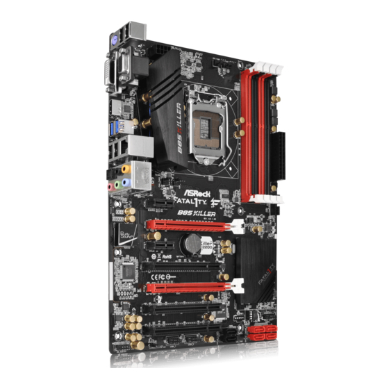
Fatal1ty B85 Killer Series 1.4 Motherboard Layout CPU_FAN2 CPU_FAN1 ATX12V1 USB 2.0 Top: T: USB2 RJ-45 B: USB3 Killer E2200 PWR_FAN1 CHA_FAN3 CHA_FAN2 PCIE1 FATAL B85 Killer PCIE2 Purity Sound CMOS PCIE3 Battery RoHS Intel PCI1 PCIE4 PCI2 PLED1 SPEAKER1... - Page 18 No. Description ATX 12V Power Connector (ATX12V1) CPU Fan Connector (CPU_FAN2) CPU Fan Connector (CPU_FAN1) 2 x 240-pin DDR3 DIMM Slots (DDR3_A1, DDR3_B1) 2 x 240-pin DDR3 DIMM Slots (DDR3_A2, DDR3_B2) ATX Power Connector (ATXPWR1) Power Fan Connector (PWR_FAN1) USB 3.0 Header (USB3_2_3) Power LED Header (PLED1) Chassis Speaker Header (SPEAKER1) System Panel Header (PANEL1)
-
Page 19: I/O Panel
Fatal1ty B85 Killer Series 1.5 I/O Panel No. Description No. Description Fatal1ty Mouse Port (USB0) Microphone (Pink) USB 2.0 Port (USB1) Optical SPDIF Out Port D-Sub Port USB 2.0 Ports (USB23) LAN RJ-45 Port* USB 3.0 Ports (USB3_0_1) Central / Bass (Orange) - Page 20 * here are two LEDs on each LAN port. Please refer to the table below for the LAN port LED indications. ACT/LINK LED SPEED LED LAN Port Activity / Link LED Speed LED Status Description Status Description No Link 10Mbps connection Blinking Data Activity Orange...
-
Page 21: Chapter 2 Installation
Fatal1ty B85 Killer Series Chapter 2 Installation his is an ATX form factor motherboard. Before you install the motherboard, study the coniguration of your chassis to ensure that the motherboard its into it. Pre-installation Precautions Take note of the following precautions before you install motherboard components or change any motherboard settings. -
Page 22: Installing The Cpu
2.1 Installing the CPU 1. Before you insert the 1150-Pin CPU into the socket, please check if the PnP cap is on the socket, if the CPU surface is unclean, or if there are any bent pins in the socket. Do not force to insert the CPU into the socket if above situation is found. - Page 23 Fatal1ty B85 Killer Series...
- Page 24 Please save and replace the cover if the processor is removed. he cover must be placed if you wish to return the motherboard for ater service.
-
Page 25: Installing The Cpu Fan And Heatsink
Fatal1ty B85 Killer Series 2.2 Installing the CPU Fan and Heatsink... -
Page 26: Dual Channel Memory Coniguration
2.3 Installing Memory Modules (DIMM) his motherboard provides four 240-pin DDR3 (Double Data Rate 3) DIMM slots, and supports Dual Channel Memory Technology. 1. For dual channel coniguration, you always need to install identical (the same brand, speed, size and chip-type) DDR3 DIMM pairs. 2. - Page 27 Fatal1ty B85 Killer Series...
-
Page 28: Expansion Slots (Pci And Pci Express Slots)
2.4 Expansion Slots (PCI and PCI Express Slots) here are 3 PCI slots and 4 PCI Express slots on the motherboard. Before installing an expansion card, please make sure that the power supply is switched of or the power cord is unplugged. Please read the documentation of the expansion card and make necessary hardware settings for the card before you start the installation. -
Page 29: Jumpers Setup
Fatal1ty B85 Killer Series 2.5 Jumpers Setup he illustration shows how jumpers are setup. When the jumper cap is placed on the pins, the jumper is “Short”. If no jumper cap is placed on the pins, the jumper is “Open”. he illustration shows a 3-pin jumper whose pin1 and pin2 are “Short”... -
Page 30: Onboard Headers And Connectors
2.6 Onboard Headers and Connectors Onboard headers and connectors are NOT jumpers. Do NOT place jumper caps over these headers and connectors. Placing jumper caps over the headers and connectors will cause permanent damage to the motherboard. PLED+ System Panel Header Connect the power PLED- PWRBTN#... - Page 31 Fatal1ty B85 Killer Series Power LED Header Please connect the chassis PLED- (3-pin PLED1) power LED to this header PLED+ PLED+ (see p.9, No. 9) to indicate the system’s power status. SATA2_0 Serial ATA2 Connectors hese two SATA2 (SATA2_0: connectors support SATA see p.9, No.
- Page 32 Front Panel Audio Header his header is for PRESENCE# MIC_RET (9-pin HD_AUDIO1) connecting audio devices OUT_RET (see p.9, No. 22) to the front audio panel. O U T 2 _ L J _ S E N S E OUT2_R MIC2_R MIC2_L 1.
- Page 33 Fatal1ty B85 Killer Series +12V CPU Fan Connectors his motherboard pro- CPU_FAN_SPEED FAN_SPEED_CONTROL (4-pin CPU_FAN1) vides a 4-Pin CPU fan (see p.9, No. 3) (Quiet Fan) connector. If you plan to connect a +12V (3-pin CPU_FAN2) 3-Pin CPU fan, please CPU_FAN_SPEED (see p.9, No.
-
Page 34: Tm Operation Guide
2.7 CrossFireX and Quad CrossFireX Operation Guide his motherboard supports CrossFireX and Quad CrossFireX that allows you to install up to two identical PCI Express x16 graphics cards. Currently CrossFireX ® and Quad CrossFireX are supported with Windows 7 / 7 64-bit / 8 / 8 64-bit OS. 1. - Page 35 Fatal1ty B85 Killer Series Step 3 Connect a VGA cable or a DVI cable to the monitor connector or the DVI connec- tor of the graphics card that is inserted to PCIE2 slot.
-
Page 36: Driver Installation And Setup
2.7.2 Driver Installation and Setup Step 1 Power on your computer and boot into OS. Step 2 Remove the AMD drivers if you have any VGA drivers installed in your system. he Catalyst Uninstaller is an optional download. We recommend using this utility to un- install any previously installed Catalyst drivers prior to installation. -
Page 37: Chapter 3 Software And Utilities Operation
Fatal1ty B85 Killer Series Chapter 3 Software and Utilities Operation 3.1 Installing Drivers he Support CD that comes with the motherboard contains necessary drivers and useful utilities that enhance the motherboard’s features. Running The Support CD To begin using the support CD, insert the CD into your CD-ROM drive. he CD automatically displays the Main Menu if “AUTORUN”... -
Page 38: F-Stream
3.2 F-Stream F-Stream is ASRock’s multi purpose sotware suite with a new interface, more new features and improved utilities, including XFast RAM, Dehumidiier, Good Night LED, FAN-Tastic Tuning, OC Tweaker and a whole lot more. 3.2.1 Installing F-Stream When you install the all-in-one driver to your system from ASRock’s support CD, F-Stream will be auto-installed as well. - Page 39 Fatal1ty B85 Killer Series Tools Various tools and utilities. XFast RAM Boost the system’s performance and extend the HDD’s or SDD’s lifespan! Create a hidden partition, then assign which iles should be stored in the RAM drive. Fast Boot Fast Boot minimizes your computer's boot time. Please note that Ultra Fast mode is only supported by Windows 8 and the VBIOS must support UEFI GOP if you are using an external graphics card.
-
Page 40: System Info
Dehumidiier Prevent motherboard damages due to dampness. Enable this function and conigure the period of time until the computer powers on, and the duration of the dehumidifying process. Key Master Enhance your mouse and keyboard with customizable macros, sniper modes, scroll speed, key repeat rates and repeat delay. - Page 41 Fatal1ty B85 Killer Series Tech Service Contact Tech Service.
-
Page 42: Killer Network Manager
3.3.1 Installing Killer Network Manager When you install the all-in-one driver to your system from ASRock’s support CD, Killer Network Manager will be auto-installed as well. Ater the installation, you will ind the icon “Killer Network Manager“... - Page 43 Fatal1ty B85 Killer Series Performance Performance allows you to view in real time your system performance and current network utilization for download and upload traic. Network Network allows you to set your preferred upload/download speeds and test the network speed.
- Page 44 Killer Ethernet Killer Ethernet displays the network information.
-
Page 45: Intel® Rapid Start Technology
Fatal1ty B85 Killer Series 3.4 Intel® Rapid Start Technology Intel® Rapid Start Technology enables your system to wake up faster from deep sleep, saving time and power consumption. Feel secure to know that your system will resume to working condition even if an unexpected power loss happens while the PC is in sleep mode. -
Page 46: Setup Guide
3.4.2 Setup Guide Coniguring Rapid Start Step 1 Run ASRock Rapid Start utility from Start -> All Programs -> ASRock Utility. Step 2 If you have more than one hard drives in your system, you must select one, then choose the Partition Size desired for your hidden partition and click on Create. he system will automatically create a hidden partition according to your settings. - Page 47 Fatal1ty B85 Killer Series Step 3 When prompted to restart ater the setup, click Yes to reboot. Step 4 Double-click the Intel® Rapid Start Technology Manager icon in the Windows system tray.
- Page 48 Step 5 Make sure Rapid Start is on. Drag the slider to conigure the time. For example, if the timer value is set to ten minutes, the system will enable Rapid Start mode ater entering sleep state for ten minutes. If the timer is set to 0 minutes, Windows will immediately enable Rapid Start mode as it enters sleep state.
- Page 49 Fatal1ty B85 Killer Series state for a period of time. he power of the computer in Rapid Start mode can be cut of, it will not cause data loss of the programs or iles you were executing before entering sleep state.
-
Page 50: Intel® Smart Connect Technology
3.5 Intel® Smart Connect Technology Intel® Smart Connect Technology is a feature that periodically wakes your computer from Windows® sleep state to refresh email or social networking applications. It saves your waiting time and keeps the content always up-to-date. 3.5.1 System Requirements •... - Page 51 3.5.2 Setup Guide Installing ASRock Smart Connect Utility Step 1 Install ASRock Smart Connect Utility, which is located in the folder at the following path of the Support CD: \ ASRock Utility > Smart Connect. Step 2 Once installed, run ASRock Smart Connect from your desktop or go to Windows...
- Page 52 Step 3 Click the Add button. Take Foxmail as an example, add Foxmail to the Application list. Step 4 Select Foxmail from the Application List, then click the arrow pointing right to add this application to the Smart Connect List. Step 5 Click Apply to enable Smart Connect.
- Page 53 Fatal1ty B85 Killer Series Step 6 Double-click the Intel® Smart Connect Technology Manager icon in the Windows system tray. Step 7 Drag the slider to conigure how oten the system will connect to the network to download updates. Shorter durations will provide more frequent updates, but may cause more power consumption.
- Page 54 he system will wake up from sleep state periodically, and then start to update Foxmail. he screen will not display anything so the computer can maintain minimum power usage. Aterwards, the system will automatically return to sleep state again. Upon waking up the system, you will ind the new mail that were sent to you during sleep state are already updated and ready to be read in Foxmail.
-
Page 55: Start8
Fatal1ty B85 Killer Series 3.6 Start8 For those Windows 8 users who miss the Start Menu, Start8 is an ideal solution that brings back the familiar Start Menu along with added customizations for greater eiciency. 3.61 Installing Start8 Install Start8, which is located in the folder at the following path of the Support CD: \ ASRock Utility >... - Page 56 Conigure Conigure provides coniguration options, including icon sizes, which shortcuts you want Start Menu to display, quick access to recently used apps, the functionality of the power button, and more. Control...
- Page 57 Fatal1ty B85 Killer Series Control lets you conigure what a click on the start button or a press on the Windows key does. Desktop Desktop allows you to disable the hot corners when you are working on the desktop. It also lets you choose whether or not the system boots directly into desktop mode and bypass the Metro user interface.
-
Page 58: Xsplit Broadcaster
3.7 XSplit Broadcaster XSplit Broadcaster is a desktop application designed to make your multimedia broadcasting, live-streaming and recording a lot easier and more fun to do, we are giving away the 3 months premium license which is worth US$24.95 for free! 3.7.1 Live Streaming Your Gameplay Step 1 Go to Start >... - Page 59 Fatal1ty B85 Killer Series Step 3 Go to Broadcast > Add Channels…. Step 4 Click Add..Step 5 Select a platform for live streaming. *Before you start streaming, you need to register an account for the streaming service website, such as Twitch.tv, USTREAM, or other livestreaming services.
- Page 60 Step 6 Fill in your platform's Username and Password. Based on your needs, conigure the Video and Audio Encoding settings. Click OK. Step 7 he channel then appears in your broadcast list. Click Apply and OK to save the settings.
-
Page 61: Recording Your Gameplay
Fatal1ty B85 Killer Series Step 8 Go to Broadcast and select the platform to enable live streaming. A link to view your live Broadcast has been copied for you automatically. Simply press CTRL-V or right click and choose Paste to paste the link into the browser, and you can see your broadcast. -
Page 62: Chapter 4 Uefi Setup Utility
Chapter 4 UEFI SETUP UTILITY 4.1 Introduction ASRock Interactive UEFI is a blend of system coniguration tools, cool sound efects and stunning visuals. Not only will it make BIOS setup less diicult but also a lot more amusing. his section explains how to use the UEFI SETUP UTILITY to conigure your system. -
Page 63: Navigation Keys
Fatal1ty B85 Killer Series 4.1.2 Navigation Keys Use < > key or < > key to choose among the selections on the menu bar, and use < > key or < > key to move the cursor up or down to select items, then press <Enter>... -
Page 64: Main Screen
When you enter the UEFI SETUP UTILITY, the Main screen will appear and display the system overview. Active Page on Entry Select the default page when entering the UEFI setup utility. UEFI Guide UEFI Guide is a quick tutorial for ASRock's UEFI setup Utility. You may abort the tutorial by pressing "esc". -
Page 65: Oc Tweaker Screen
Fatal1ty B85 Killer Series 4.3 OC Tweaker Screen In the OC Tweaker screen, you can set up overclocking features. Because the UEFI sotware is constantly being updated, the following UEFI setup screens and descriptions are for reference purpose only, and they may not exactly match what you see on your screen. -
Page 66: Long Duration Maintained
CPU OC Fixed Mode he CPU speed is determined by the CPU Ratio multiplied with the BCLK. Increasing the BCLK will increase the internal CPU clock speed but also afect the clock speed of other components. Intel SpeedStep Technology Intel SpeedStep technology allows processors to switch between multiple frequen- cies and voltage points for better power saving and heat dissipation. -
Page 67: Dram Timing Coniguration
Fatal1ty B85 Killer Series GT Voltage Mode Auto: For optimized settings. Adaptive: Add voltage to the integrated GPU when the system is under heavy load. Override: he voltage is ixed. GT Adaptive Voltage Conigure the ixed voltage added to the integrated GPU. - Page 68 DRAM Tweaker Fine tune the DRAM settings by leaving marks in checkboxes. Click OK to conirm and apply your new settings. CAS# Latency (tCL) he time between sending a column address to the memory and the beginning of the data in response.
- Page 69 Fatal1ty B85 Killer Series Read to Precharge (tRTP) he number of clocks that are inserted between a read command to a row pre- charge command to the same rank. Four Activate Window (tFAW) he time window in which four activates are allowed the same rank.
- Page 70 tWRWRDD Conigure between module write to write delay from diferent DIMMs. tRDWR Conigure between module read to write delay. tRDWRDR Conigure between module read to write delay from diferent ranks. tRDWRDD Conigure between module read to write delay from diferent DIMMs. RTL (CHA) Conigure round trip latency for channel A.
-
Page 71: Fivr Coniguration
Fatal1ty B85 Killer Series MRC Fast Boot Enable Memory Fast Boot to skip DRAM memory training for booting faster. DIMM Exit Mode Select Slow Exit to reduce power consumption, or Fast Exit for better performance. FIVR Coniguration FIVR Switch Frequency Signature Select whether to boost or lower the FIVR Switch Frequency. -
Page 72: Voltage Coniguration
CPU Integrated VR Eiciency Mode Enable FIVR Eiciency Management for power saving. Disable for better performance and overclocking capabilities. Voltage Coniguration CPU Input Voltage Conigure the voltage for the CPU. CPU Load-Line Calibration CPU Load-Line Calibration helps prevent CPU voltage droop when the system is under heavy load. -
Page 73: Advanced Screen
Fatal1ty B85 Killer Series 4.4 Advanced Screen In this section, you may set the conigurations for the following items: CPU Coniguration, Chipset Coniguration, Storage Coniguration, Intel® Rapid Start Technology, Intel® Smart Connect Technology, Super IO Coniguration, ACPI Con- iguration and USB Coniguration. -
Page 74: Cpu Coniguration
4.4.1 CPU Coniguration Active Processor Cores Select the number of cores to enable in each processor package. CPU C States Support Enable CPU C States Support for power saving. It is recommended to keep C3, C6 and C7 all enabled for better power saving. Enhanced Halt State (C1E) Enable Enhanced Halt State (C1E) for lower power consumption. -
Page 75: Intel Virtualization Technology
Fatal1ty B85 Killer Series CPU Thermal Throttling Enable CPU internal thermal control mechanisms to keep the CPU from overheat- ing. No-Execute Memory Protection Processors with No-Execution Memory Protection Technology may prevent certain classes of malicious bufer overlow attacks. Intel Virtualization Technology... -
Page 76: Chipset Coniguration
4.4.2 Chipset Coniguration Primary Graphics Adapter Select a primary VGA. VT-d Intel® Virtualization Technology for Directed I/O helps your virtual machine monitor better utilize hardware by improving application compatibility and reliability, and providing additional levels of manageability, security, isolation, and I/O performance. - Page 77 Fatal1ty B85 Killer Series Render Standby Power down the render unit when the GPU is idle for lower power consumption. Onboard HD Audio Enable/disable onboard HD audio. Set to Auto to enable onboard HD audio and automatically disable it when a sound card is installed.
-
Page 78: Storage Coniguration
4.4.3 Storage Coniguration SATA Controller(s) Enable/disable the SATA controllers. SATA Mode Selection IDE: For better compatibility. AHCI: Supports new features that improve performance. RAID: Combine multiple disk drives into a logical unit. AHCI (Advanced Host Controller Interface) supports NCQ and other new features that will improve SATA disk performance but IDE mode does not have these advan- tages. -
Page 79: Intel® Rapid Start Technology
Fatal1ty B85 Killer Series 4.4.4 Intel® Rapid Start Technology ® Intel Rapid Start Technology Intel® Rapid Start Technology is a new zero power hibernation mode which allows users to resume in just 5-6 seconds. -
Page 80: Intel® Smart Connect Technology
4.4.5 Intel® Smart Connect Technology ® Intel Smart Connect Technology ® Intel Smart Connect Technology automatically updates your email and social networks, such as Twitter, Facebook, etc. while the computer is in sleep mode. -
Page 81: Super Io Coniguration
Fatal1ty B85 Killer Series 4.4.6 Super IO Coniguration PS2 Y-Cable Enable the PS2 Y-Cable or set this option to Auto. -
Page 82: Acpi Coniguration
4.4.7 ACPI Coniguration Suspend to RAM Select disable for ACPI suspend type S1. It is recommended to select auto for ACPI S3 power saving. Check Ready Bit Enable to enter the operating system ater S3 only when the hard disk is ready, this is recommended for better system stability. - Page 83 Fatal1ty B85 Killer Series RTC Alarm Power On Allow the system to be waked up by the real time clock alarm. Set it to By OS to let it be handled by your operating system. USB Keyboard/Remote Power On Allow the system to be waked up by an USB keyboard or remote controller.
-
Page 84: Usb Coniguration
4.4.8 USB Coniguration USB Controller Enable or disable all the USB 2.0 ports. Intel USB 3.0 Mode Enable or disable all the USB 3.0 ports. Legacy USB Support Enable or disable Legacy OS Support for USB 2.0 devices. If you encounter USB compatibility issues it is recommended to disable legacy USB support. -
Page 85: Tools
In order to prevent users from bypassing OMG, guest accounts without permission to modify the system time are required. UEFI Tech Service Contact ASRock Tech Service if you are having trouble with your PC. Please setup network coniguration before using UEFI Tech Service. Easy Driver Installer For users that don’t have an optical disk drive to install the drivers from our support... -
Page 86: Network Coniguration
Internet Flash ASRock Internet Flash downloads and updates the latest UEFI irmware version from our servers for you. Please setup network coniguration before using Internet Flash. *For BIOS backup and recovery purpose, it is recommended to plug in your USB pen drive before using this function. - Page 87 Fatal1ty B85 Killer Series Dehumidiier Function If Dehumidiier Function is enabled, the computer will power on automatically to dehumidify the system ater entering S4/S5 state. Dehumidiier Period Conigure the period of time until the computer powers on and enables Dehumidiier ater entering S4/S5 state.
-
Page 88: Hardware Health Event Monitoring Screen
4.6 Hardware Health Event Monitoring Screen his section allows you to monitor the status of the hardware on your system, including the parameters of the CPU temperature, motherboard temperature, fan speed and voltage. CPU Fan 1 & 2 Setting Select a fan mode for CPU Fans 1&2, or choose Customize to set 5 CPU temperatures and assign a respective fan speed for each temperature. -
Page 89: Boot Screen
Fatal1ty B85 Killer Series 4.7 Boot Screen his section displays the available devices on your system for you to conigure the boot settings and the boot priority. Fast Boot Fast Boot minimizes your computer's boot time. In fast mode you may not boot from an USB storage device. - Page 90 Full Screen Logo Enable to display the boot logo or disable to show normal POST messages. AddOn ROM Display Enable AddOn ROM Display to see the AddOn ROM messages or conigure the AddOn ROM if you've enabled Full Screen Logo. Disable for faster boot speed. Boot Failure Guard If the computer fails to boot for a number of times the system automatically restores the default settings.
- Page 91 Fatal1ty B85 Killer Series Launch PXE OpROM Policy Select UEFI only to run those that support UEFI option ROM only. Select Legacy only to run those that support legacy option ROM only. Launch Storage OpROM Policy Select UEFI only to run those that support UEFI option ROM only. Select Legacy only to run those that support legacy option ROM only.
-
Page 92: Security Screen
4.8 Security Screen In this section you may set or change the supervisor/user password for the system. You may also clear the user password. Supervisor Password Set or change the password for the administrator account. Only the administrator has authority to change the settings in the UEFI Setup Utility. Leave it blank and press enter to remove the password. -
Page 93: Exit Screen
Fatal1ty B85 Killer Series 4.9 Exit Screen Save Changes and Exit When you select this option the following message, “Save coniguration changes and exit setup?” will pop out. Select [OK] to save changes and exit the UEFI SETUP UTILITY. Discard Changes and Exit When you select this option the following message, “Discard changes and exit... -
Page 94: Contact Information
Contact Information If you need to contact ASRock or want to know more about ASRock, you’re welcome to visit ASRock’s website at http://www.asrock.com; or you may contact your dealer for further information. For technical questions, please submit a support request form at http://www.asrock.com/support/tsd.asp...