Table of Contents
Advertisement
Quick Links
Advertisement
Table of Contents

Related Manuals for ASROCK M8


Summary of Contents for ASROCK M8
- Page 1 User Manual...
-
Page 2: Copyright Notice
(including damages for loss of proits, loss of business, loss of data, interruption of business and the like), even if ASRock has been advised of the possibility of such damages arising from any defect or error in the documentation or product. -
Page 3: Important Safety Instructions
Important Safety Instructions Pay close attention to the following safety instructions before performing any of the operation. Basic safety precautions should be followed to protect yourself from harm and the product from damage: • Operation of the product should be carried out by suitably trained, qualiied, and certiied personnel only to avoid risk of injury from electrical shock or energy hazard. -
Page 4: Contact Information
Contact Information If you need to contact ASRock or want to know more about ASRock, you’re welcome to visit ASRock’s website at http://www.asrock.com; or you may contact your dealer for further information. For technical questions, please submit a support request form at http://www.asrock.com/support/tsd.asp... -
Page 5: Chapter 1 Introduction
In case any modiications of this documentation occur, the updated version will be available on ASRock’s website without further notice. If you require technical support related to this product, please visit our website for speciic information about the model you are using. -
Page 6: Product Speciications
Color • Steel Body / Aluminum + Plastic Material • 372mm (W) x 123mm (H) x 400mm (L) Dimension • ASRock Z87-M8 Motherboard • Supports 4 Gen Intel® Core i7 / i5 / i3 / Xeon® / Pentium® / Celeron® Processor Family • Supports DDR3 1600/1333/1066 MHz, 2 x SO-DIMM... - Page 7 * Max. Supported VGA Dimension: 290mm x 137mm x 43.5mm; Max. Supported TDP: 200W (If you use a graphics card with over 200W TDP, please note that the system’s power supply is only 450W.)
-
Page 8: Unique Features
LED, FAN-Tastic Tuning, OC Tweaker and a whole lot more. ASRock Instant Flash ASRock Instant Flash is a BIOS lash utility embedded in Flash ROM. his conve- nient BIOS update tool allows you to update the system BIOS in a few clicks without preparing an additional loppy diskette or other complicated lash utility. - Page 9 And it also boosts the speed of Adobe Photoshop 5 times faster. Another advantage of ASRock XFast RAM is that it reduces the frequency of accessing your SSDs or HDDs in order to extend their lifespan.
- Page 10 Windows® 8 brings the ultimate boot up experience. he lightning boot up speed makes it hard to access the UEFI setup. ASRock Restart to UEFI allows users to enter the UEFI automatically when turning on the PC. By enabling this function, the PC will enter the UEFI directly ater you restart.
- Page 11 ASRock Easy Driver Installer For users that don’t have an optical disk drive to install the drivers from our support CD, Easy Driver Installer is a handy tool in the UEFI that installs the LAN driver to your system via an USB storage device, then downloads and installs the other required drivers...
-
Page 12: Chapter 2 Product Overview
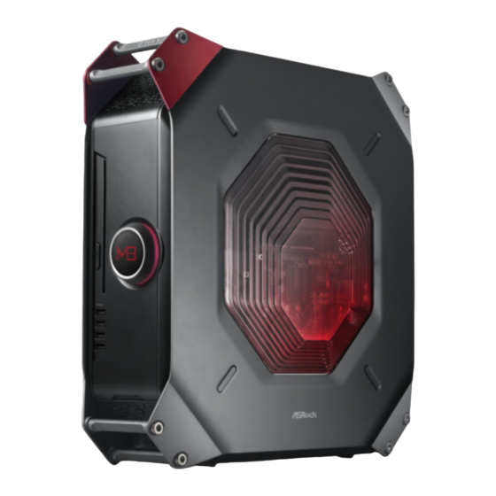
Chapter 2 Product Overview his chapter provides diagrams showing the location of important components of the M8. 2.1 Front View Description A-Command (All-In-One OLED Button) Optical disk drive eject button 4 x USB 3.0 ports 4-in-1 Card reader (SD3.0/MMC/MS/MS PRO) -
Page 13: Powering On The System
Toggle on/of the light in the case. • Time: Toggle the time on/of. If this option is set to on, M8 Logo / Date and Time screens are available. If this option is set to of, M8 Logo / Date and Time screens are hidden. -
Page 14: Under Windows
Standby/Hibernation mode as well. • Time: Toggle the time on/of. If this option is set to on, M8 Logo / Date and Time screens are available. If this option is set to of, M8 Logo / Date and Time screens are hidden. -
Page 15: Rear View
2.2 Rear View Description PCIe slot covers I/O panel AC input power connector... - Page 16 2.2.1 I/O Panel...
- Page 17 No. Description No. Description Line In port (light blue) eSATA2 port** Line Out port (lime) DisplayPort Center/Subwoofer port (orange) HDMI port Rear Speaker Out port (black) USB3.0 port LAN RJ-45 port* (Intel Gigabit LAN) 14 USB3.0 port USB2.0 ports USB3.0 port USB2.0 ports USB3.0 port USB2.0 ports...
-
Page 18: Inside View
2.3 Inside View Description Riser card retention bracket VGA card holder Hard disk drive tray (compatible with 4 x 2.5" HDD or 1 x 3.5 HDD) ODD + 2.5" HDD Tray (compatible with 1 x slot-in ODD and 1 x 2.5" HDD) Power supply unit (450W) Power panel connector SATA 3.0 connectors... - Page 19 Front audio connector USB3.0 connector Auxiliary fan connector 2T2R WiFi Module (802.11ac) CPU socket DIMM sockets Chassis fan connector ATX 12V power connector Hard drives are not included with this system.
-
Page 20: Chapter 3 Hardware Installation
Chapter 3 Hardware Installation his chapter helps you assemble the chassis and install components. Please follow the installation procedures listed below. Installation Procedures Removing the side panels Removing the top cover Removing the VGA card holder Removing the riser card Installing the hard drives Installing the CPU Installing the CPU Fan and CPU Cooler... -
Page 21: Installing System Components
3.1 Installing System Components 3.1.1 Removing the Side Panels To remove the side panels, you have to unlock the keylock on the top cover using the system key. Before unlocking, power of the system and unplug the power cord. Ater the side panel are replaced, make sure to lock the keylock on the top cover and then power on the system. -
Page 22: Removing The Top Cover
3.1.2 Removing the Top Cover 1. To remove the top cover, you have to follow the procedures below: 1) Power of the system and unplug the power cord. 2) Unlock the keylock on the top cover using the system key. 3) Follow the instructions in Section 3.1 to remove the right side panel. - Page 23 5. Draw out the mounting bracket from the chassis. 6. Follow the instructions in Section 3.1 to release the let side panel. 7. Release the top cover. Slide the top cover toward the front of the system until it releases. Lit up the top cover.
- Page 24 3.1.3 Removing the VGA Card Holder To remove the VGA card holder, you have to remove the side panels and top cover, giving you access to the VGA card holder inside. 1. Remove the VGA card holder. Remove the two screws that hold the VGA card holder in place. Lit the VGA card holder up and of the chassis.
-
Page 25: Removing The Riser Card
3.1.4 Removing the Riser Card 1. Remove the riser card. Remove the two screws securing the riser card retention bracket. Grasp the riser card by its edges, and carefully pull it from the expansion slot. -
Page 26: Installing The Hard Drives
3.1.5 Installing the Hard Drives 3.1.5.1 Installing the Hard Drive(s) to the Drive Tray Assembly 1. To install the hard drives, you have to remove the VGA card holder and the riser card , giving you access to the drive tray assembly inside. 2. - Page 27 2. Take apart the drive tray assembly. Remove the screws that secure the bottom HDD tray with the top tray. Take the assembly apart. 3. Install a 3.5" HDD or up to four 2.5" HDD. Installing a 3.5-Inch Hard Drive: Set the top tray aside.
- Page 28 Installing up to Four 2.5-Inch Hard Drive Place the irst 2.5" HDD to the bottom HDD tray and secure the hard drive using the four screws (two on the sides and two in the rear). Place the second 2.5" HDD to the top HDD tray and secure the hard drive using the four screws.
-
Page 29: Installing A 2.5-Inch Hard Drive
3.1.5.2 Installing the Hard Drive to the ODD + 2.5" HDD Tray 1. To install the hard drives, you have to remove the PSU. 2. he ODD + 2.5” HDD Tray its a slim slot-in optical disk drive (ODD) and a 2.5-inch hard drives. - Page 30 2. Remove the ODD+2.5" HDD Tray. Unplug the ODD SATA power connector. Remove the ive screws securing the ODD + 2.5" HDD Tray to the chassis. Lit the tray of the chassis. 3. Place a 2.5" HDD to the HDD tray and secure the hard drive using the four screws (four in the rear).
- Page 31 4. Align the screw holes on the ODD + 2.5" HDD Tray with the screw holes on the chassis. Fasten the ive screws. 5. Connect the power and SATA data cables and the ODD SATA power connector. 6. Re-install the PSU. Align the PSU with the starting line and then slide the PSU to the let until it reaches the end line.
-
Page 32: Replacing The Odd
3.1.6 Replacing the ODD 1. Follow the instructions in section 3.1.5.2 to remove the power supply unit and lit the tray of the chassis. 2. Remove the old optical disk drive. 3. Slide a new optical disk drive into the ODD tray. 4. -
Page 33: Installing The Cpu
3.1.7 Installing the CPU 1. Before you insert the 1150-Pin CPU into the socket, please check if the PnP cap is on the socket, if the CPU surface is unclean, or if there are any bent pins in the socket. Do not force to insert the CPU into the socket if above situation is found. - Page 34 English...
- Page 35 Please save and replace the cover if the processor is removed. he cover must be placed if you wish to return the motherboard for ater service.
- Page 36 3.1.8 Installing the CPU Fan and CPU Cooler...
- Page 37 1. Make sure to evenly spread the thermal paste over the CPU to improve heat dissipation. 2. Ensure that the CPU and the CPU cooler are securely fastened and in good contact with each other. 3. To make sure the CPU cooler is seated properly, it is highly recommended to check whether or not the CPU temperature reported in the BIOS is at a normal level.
-
Page 38: Installing Memory Modules (So-Dimm)
3.1.9 Installing Memory Modules (SO-DIMM) his motherboard provides two 204-pin DDR3 (Double Data Rate 3) SO-DIMM slots. It is not allowed to install a DDR or DDR2 memory module into a DDR3 slot; otherwise, this motherboard and SO-DIMM may be damaged. he DIMM only its in one correct orientation. - Page 40 3.2 Replacing System Components 3.2.1 Replacing the Riser Card 1. Replace the riser card. Align the riser card keys correctly with the expansion slot on the system board and insert it into place. Fasten the two screws securing the riser card retention bracket.
-
Page 41: Installing The Graphics Card
3.2.2 Installing the Graphics Card he M8 chassis supports both single-slot graphics card and dual-slot graphics card. Before graphics card installation, please lit the VGA card holder and make sure the riser card is installed properly. 1. Open the latch of the VGA card holder and remove the screws that secures the slot cover. - Page 42 5. Engage the VGA card holder with the two vertical sliding tracks while sliding it back to the chassis. 6. Make sure the VGA card holder is secured by the tongue plate and the graphics card is seated correctly. 7. Secure the VGA card holder with the chassis using the two screws previously removed.
-
Page 43: Replacing The Top Cover
3.2.3 Replacing the Top Cover 1. Place the system in an upright position. 2. Make sure to release the let side panel. 3. Connect the 4-pin top fan connector. 4. Replace the top cover. Replace the top cover onto the chassis. Slide the top cover toward the rear of the system until it clicks into place. - Page 44 5. Insert the mounting bracket into the mounting holes. 6. Secure it to the case with the three screws previously removed.
-
Page 45: Replacing The Side Panels
3.2.1 Replacing the Side Panels 1. Place the system in an upright position. 2. Replace the side panels. Snap the right side panel into place. Snap the let side panel into place. 3. Lock the system keylock on the top cover. -
Page 46: Chapter 4 Motherboard
Chapter 4 Motherboard 4.1 Motherboard Layout PCIE1 SATA3_1 USB_1_2 64Mb HD_AUDIO1 BIOS SATA3_2 SATA3_5 MINI_PCIE1 PANEL1 Intel Sound CORE3D SATA3_6 WiFi-802.11ac SATA3_3 Module SATA3_4 USB 3.0 T: USB0 CMOS B: USB1 Battery USB 3.0 Top: T: USB4 RJ-45 B: USB5 USB 2.0 T: USB6 B: USB7... - Page 47 No. Description System Panel Header (PANEL1) LPC Debug Header (LPC1) SATA3 Connectors (SATA3_1, SATA3_2, SATA3_3, SATA3_4, SATA3_5, SATA3_6) Clear CMOS Jumper (CLRCMOS1) Auxiliary Fan Connector (AUX_FAN1) USB 2.0 Header (USB_1_2) mini-PCI Express Slot (MINI_PCIe1) WiFi-802.11ac Module Front Panel Audio Header (HD_AUDIO1) CPU Fan Connector (CPU_FAN1) ATX 12V Power Connector (ATX12V1) Chassis Fan Connector (CHA_FAN1)
-
Page 48: Jumpers Setup
4.2 Jumpers Setup he illustration shows how jumpers are setup. When the jumper cap is placed on the pins, the jumper is “Short”. If no jumper cap is placed on the pins, the jumper is “Open”. he illustration shows a 3-pin jumper whose pin1 and pin2 are “Short” when a jumper cap is placed on these 2 pins. -
Page 49: Onboard Headers And Connectors
4.3 Onboard Headers and Connectors Onboard headers and connectors are NOT jumpers. Do NOT place jumper caps over these headers and connectors. Placing jumper caps over the headers and connectors will cause permanent damage to the motherboard. System Panel Header Connect the power HDLED+ PLED+... - Page 50 Serial ATA3 Connectors hese six SATA3 SATA3_1 (SATA3_1) connectors support SATA (SATA3_2) data cables for internal SATA3_2 (SATA3_5) storage devices with up to (SATA3_6) 6.0 Gb/s data transfer rate. SATA3_5 (SATA3_3) SATA3_4 connector is (SATA3_4) shared with the eSATA SATA3_6 (see p.41, No.
- Page 51 Front Panel Audio Header MIC2_L his header is for MIC2_R (9-pin HD_AUDIO1) OUT2_R connecting audio devices J_SENSE (see p.41, No. 9) to the front audio panel. OUT2_L OUT_RET MIC_RET PRESENCE# GN D 1. High Deinition Audio supports Jack Sensing, but the panel wire on the chassis must sup- port HDA to function correctly.
- Page 52 ATX Power Connector his motherboard pro- (24-pin ATXPWR1) vides a 24-pin ATX power (see p.41, No. 5) connector. To use a 20-pin ATX power supply, please plug it along Pin 1 and Pin ATX 12V Power his motherboard Connector provides a 4-pin ATX 12V (4-pin ATX12V1) power connector.
-
Page 53: Chapter 5 Software And Utilities Operation
Chapter 5 Software and Utilities Operation 5.1 Installing Drivers he Support CD that comes with the M8 contains necessary drivers and useful utilities that enhance the M8’s features. Running The Support CD To begin using the support CD, insert the CD into your CD-ROM drive. he CD automatically displays the Main Menu if “AUTORUN”... -
Page 54: Operation Mode
5.2 A-Tuning A-Tuning is ASRock’s multi purpose sotware suite with a new interface, more new features and improved utilities, including XFast RAM, Dehumidiier, Good Night LED, FAN-Tastic Tuning, OC Tweaker and a whole lot more. 5.2.1 Installing A-Tuning When you install the all-in-one driver to your system from ASRock’s support CD, A-Tuning will be auto-installed as well. - Page 55 Tools Various tools and utilities. XFast RAM Boost the system’s performance and extend the HDD’s or SDD’s lifespan! Create a hidden partition, then assign which iles should be stored in the RAM drive. XFast LAN Boost the speed of your internet connection! Select a speciic mode for making the designated program's priority highest.
- Page 56 Dehumidiier Prevent motherboard damages due to dampness. Enable this function and conigure the period of time until the computer powers on, and the duration of the dehumidifying process. Key Master Enhance your mouse and keyboard with customizable macros, sniper modes, scroll speed, key repeat rates and repeat delay.
-
Page 57: System Info
OC Tweaker Conigurations for overclocking the system. System Info View information about the system. -
Page 58: Live Update
Live Update Check for newer versions of BIOS, A-Tuning or drivers. Tech Service Contact Tech Service. - Page 59 Settings Conigure ASRock A-Tuning.
- Page 60 5.3 SBX Pro Studio his section explains how to conigure the Creative Sound Core3D using SBX Pro Studio. Click the power button on the let to activate or deactivate. Surround Control the level of audio immersion in music, movies and games. Crystalizer Enhance music and movies to make them sound livelier.
- Page 61 CRYSTALVOICE Select a recording device Mic Volume Control the level of mic volume. Mic Boost Control the level of mic boost. CrystalVoice Click the power button on the let to activate or deactivate. Morph your voice into diferent characters and accents. Smart Volume Be heard clearly without having to shout or whisper.
- Page 62 SCOUT MODE Scout Mode Enable or disable scout mode. his proprietary technology allows you to hear your enemies from further away, giving you a distinct tactical advantage in combat. Hot Key Coniguration Conigure hot keys to enable or disable scout mode.
- Page 63 SPEAKERS/HEADPHONES Speakers / Headphones Coniguration Select the device connected. If there are both speakers and front headphones connected, please select the device you desire to use as audio output. Optional Speakers Center Enable or disable center speaker. Subwoofer Enable or disable subwoofer. Rear pair Enable or disable rear pair speakers.
- Page 64 Bass Management Bass Redirection Enable or disable bass redirection. Subwoofer Gain Enable or disable subwoofer gain. Crossover Frequency Redirect all frequencies below this value to the optimal speaker for better bass response. MIXER Playback Speakers Control the level of speakers playback. SPDIF-Out Control the level of SPDIF-Out playback.
- Page 65 What U Hear Control the level of playback redirect. EQUALIZER Choose from Flat, Acoustic, Classical, Country, Dance, Jazz, New Age, Pop, Rock and Vocal. JACK SETUP Device Connected: Select the device connected. Show Jack Setup dialog when an audio jack is inserted Enable or disable Jack Setup dialog.
- Page 66 ADVANCED FEATURES Play stereo mix to digital output Enable or disable play stereo mix to digital output. PROFILE...
- Page 67 User Proiles You can save, load or delete your user proiles. he default is <Custom>. Note If you want to hear your own voice through the microphone (Playback mode). You can change your settings to "playback mode" by checking the "Listen to this device"...
-
Page 68: Intel® Rapid Start Technology
5.4 Intel® Rapid Start Technology Intel® Rapid Start Technology enables your system to wake up faster from deep sleep, saving time and power consumption. Feel secure to know that your system will resume to working condition even if an unexpected power loss happens while the PC is in sleep mode. -
Page 69: Setup Guide
5.4.2 Setup Guide Coniguring Rapid Start Step 1 Run ASRock Rapid Start utility from Start -> All Programs -> ASRock Utility. Step 2 If you have more than one hard drives in your system, you must select one, then choose the Partition Size desired for your hidden partition and click on Create. he system will automatically create a hidden partition according to your settings. - Page 70 Step 3 When prompted to restart ater the setup, click Yes to reboot. Step 4 Double-click the Intel® Rapid Start Technology Manager icon in the Windows system tray.
- Page 71 Step 5 Make sure Rapid Start is on. Drag the slider to conigure the time. For example, if the timer value is set to ten minutes, the system will enable Rapid Start mode ater entering sleep state for ten minutes. If the timer is set to 0 minutes, Windows will immediately enable Rapid Start mode as it enters sleep state.
- Page 72 will automatically wake up and enable Rapid Start mode ater entering sleep state for a period of time. he power of the computer in Rapid Start mode can be cut of, it will not cause data loss of the programs or iles you were executing before entering sleep state.
-
Page 73: Intel® Smart Connect Technology
5.5 Intel® Smart Connect Technology Intel® Smart Connect Technology is a feature that periodically wakes your computer from Windows® sleep state to refresh email or social networking applications. It saves your waiting time and keeps the content always up-to-date. 5.5.1 System Requirements •... - Page 74 Installing ASRock Smart Connect Utility Step 1 Install ASRock Smart Connect Utility, which is located in the folder at the following path of the Support CD: \ ASRock Utility > Smart Connect. Step 2 Once installed, run ASRock Smart Connect from your desktop or go to Windows Start -> All Programs -> ASRock Utility.
- Page 75 Step 3 Click the Add button. Take Foxmail as an example, add Foxmail to the Application list. Step 4 Select Foxmail from the Application List, then click the arrow pointing right to add this application to the Smart Connect List. Step 5 Click Apply to enable Smart Connect.
- Page 76 Step 6 Double-click the Intel® Smart Connect Technology Manager icon in the Windows system tray. Step 7 Drag the slider to conigure how oten the system will connect to the network to download updates. Shorter durations will provide more frequent updates, but may cause more power consumption.
- Page 77 he system will wake up from sleep state periodically, and then start to update Foxmail. he screen will not display anything so the computer can maintain minimum power usage. Aterwards, the system will automatically return to sleep state again. Upon waking up the system, you will ind the new mail that were sent to you during sleep state are already updated and ready to be read in Foxmail.
-
Page 78: Intel® Remote Wake Technology
5.6 Intel® Remote Wake Technology Intel® Remote Wake Technology allows you to use programs or services over the Internet to wake up your home computer from energy eicient sleep mode. Before coniguring this feature, verify the following. • Remote Wake has been enabled in "Intel® Smart Connect Technology Manager". - Page 79 Step 2 Click the "My Account" tab. hen click on "New" to create a new mesh. Step 3 A new mesh window will pop up. Enter a mesh name and password. Step 4 Select all the checkboxes and click Create Mesh. Downloading and Installing Mesh Agent Step 1 Click Install on the My Account page.
- Page 80 Step 4 Click Install / Update. Step 5 Wait a minute for the New Machine to appear in "My Device".
- Page 81 Step 6 Check whether "Intel Remote Wake" appeared or not. Waking up Your PC using PC Step 1 On the "My Devices" page, click on Power Actions. Step 2 Click on Wake or Sleep.
- Page 82 Waking up Your PC Using Mobile Device Before waking up your home computer using a mobile device, please log out of MeshCentral on other previously used computers or devices. Step 1 Login to meshcentral.com/m. Step 2 Select a Machine. Step 3 Click on Wake or Sleep.
- Page 83 Step 1 Download and install the Streamer on your home computer, which is located in the folder at the following path of the Support CD: \ ASRock Utility > Splashtop Streamer. hen enter your Splashtop Account. If you have not created a Splashtop acount, create one.
-
Page 84: Using Remote Control
Using Remote Control Step 1 In "Splashtop 2”, tap an online machine from the list to connect to your home computer. Step 2 Start remotely accessing your home computer. he functionality and price of the Splashtop APP and subscription fee is subject to change. - Page 85 Accessing Data Playing Video...
- Page 86 5.7.1 Installing Start8 Install Start8, which is located in the folder at the following path of the Support CD: \ ASRock Utility > Start8. 5.7.2 Coniguring Start8 Style Select between the Windows 7 style and Windows 8 style Start Menu. hen select...
- Page 87 Conigure Conigure provides coniguration options, including icon sizes, which shortcuts you want Start Menu to display, quick access to recently used apps, the functionality of the power button, and more. Control...
- Page 88 Control lets you conigure what a click on the start button or a press on the Windows key does. Desktop Desktop allows you to disable the hot corners when you are working on the desktop. It also lets you choose whether or not the system boots directly into desktop mode and bypass the Metro user interface.
- Page 89 5.8 XSplit Broadcaster XSplit Broadcaster is a desktop application designed to make your gameplay broadcasting, live-streaming and recording a lot easier and more fun to do, we are giving away the 3 months premium license which is worth US$24.95 for free! 5.8.1 Live Streaming Your Gameplay Step 1 Go to Start > All Programs > XSplit > XSplit Broadcaster to launch it.
- Page 90 Step 3 Go to Broadcast > Add Channels…. Step 4 Click Add..Step 5 Select a platform for live streaming. *Before you start streaming, you need to register an account for the streaming service website, such as Twitch.tv, USTREAM, or other livestreaming services.
- Page 91 Step 6 Fill in your platform's Username and Password. Based on your needs, conigure the Video and Audio Encoding settings. Click OK. Step 7 he channel then appears in your broadcast list. Click Apply and OK to save the settings.
- Page 92 Step 8 Go to Broadcast and select the platform to enable live streaming. A link to view your live Broadcast has been copied for you automatically. Simply press CTRL-V or right click and choose Paste to paste the link into the browser, and you can see your broadcast.
-
Page 93: Chapter 6 Uefi Setup Utility
Chapter 6 UEFI SETUP UTILITY 6.1 Introduction ASRock Interactive UEFI is a blend of system coniguration tools, cool sound efects and stunning visuals. Not only will it make BIOS setup less diicult but also a lot more amusing. his section explains how to use the UEFI SETUP UTILITY to conigure your system. -
Page 94: Navigation Keys
6.1.2 Navigation Keys Use < > key or < > key to choose among the selections on the menu bar, and use < > key or < > key to move the cursor up or down to select items, then press <Enter>... -
Page 95: Main Screen
When you enter the UEFI SETUP UTILITY, the Main screen will appear and display the system overview. Active Page on Entry Select the default page when entering the UEFI setup utility. UEFI Guide UEFI Guide is a quick tutorial for ASRock's UEFI setup Utility. You may abort the tutorial by pressing "esc". -
Page 96: Oc Tweaker Screen
6.3 OC Tweaker Screen In the OC Tweaker screen, you can set up overclocking features. Because the UEFI sotware is constantly being updated, the following UEFI setup screens and descriptions are for reference purpose only, and they may not exactly match what you see on your screen. -
Page 97: Long Duration Maintained
CPU Cache Ratio he CPU Internal Bus Speed Ratio. he maximum should be the same as the CPU Ratio. BCLK/PCIE Frequency he CPU speed is determined by the CPU Ratio multiplied with the BCLK. Increasing the BCLK will increase the internal CPU clock speed but also afect the clock speed of other components. - Page 98 Short Duration Power Limit Conigure Package Power Limit 2 in watts. When the limit is exceeded, the CPU ratio will be lowered immediately. A lower limit can protect the CPU and save power, while a higher limit may improve performance. Primary Plane Current Limit Conigure the current limit of the CPU under Turbo Mode in ampere.
- Page 99 DRAM Coniguration DRAM Tweaker Fine tune the DRAM settings by leaving marks in checkboxes. Click OK to conirm and apply your new settings. CAS# Latency (tCL) he time between sending a column address to the memory and the beginning of the data in response.
- Page 100 RAS# Active Time (tRAS) he number of clock cycles required between a bank active command and issuing the precharge command. Command Rate (CR) he delay between when a memory chip is selected and when the irst active command can be issued. Write Recovery Time (tWR) he amount of delay that must elapse ater the completion of a valid write operation, before an active bank can be precharged.
- Page 101 tREFI Conigure refresh cycles at an average periodic interval. tCKE Conigure the period of time the DDR3 initiates a minimum of one refresh command internally once it enters Self-Refresh mode. tRDRD Conigure between module read to read delay. tRDRDDR Conigure between module read to read delay from diferent ranks. tRDRDDD Use this to change DRAM tRWSR Auto/Manual settings.
- Page 102 tRDWR Conigure between module read to write delay. tRDWRDR Conigure between module read to write delay from diferent ranks. tRDWRDD Conigure between module read to write delay from diferent DIMMs. RTL (CHA) Conigure round trip latency for channel A. RTL (CHB) Conigure round trip latency for channel B.
- Page 103 Command Tri State Enable for DRAM power saving. MRC Fast Boot Enable Memory Fast Boot to skip DRAM memory training for booting faster. FIVR Coniguration FIVR Switch Frequency Signature Select whether to boost or lower the FIVR Switch Frequency. FIVR Switch Frequency Ofset Conigure the percentage of frequency boost or deduction.
- Page 104 CPU Cache Voltage Ofset Conigure the voltage for the CPU Cache. Setting the voltage higher may increase system stability when overclocking. System Agent Voltage Ofset Conigure the voltage for the System Agent. Setting the voltage higher may increase system stability when overclocking. CPU Analog IO Voltage Ofset CPU I/O Analog Voltage.
-
Page 105: Dram Voltage
DRAM Voltage Use this to conigure DRAM Voltage. he default value is [Auto]. PCH 1.05V Voltage Chipset 1.05V Voltage. Use default settings for best performance. PCH 1.5V Voltage I/O 1.5V Voltage. Use default settings for best performance. -
Page 106: Advanced Screen
6.4 Advanced Screen In this section, you may set the conigurations for the following items: CPU Conigu- ration, Chipset Coniguration, Storage Coniguration, Intel® Rapid Start Technology, Intel® Smart Connect Technology, ACPI Coniguration and USB Coniguration. Setting wrong values in this section may cause the system to malfunction. -
Page 107: Cpu Coniguration
6.4.1 CPU Coniguration Active Processor Cores Select the number of cores to enable in each processor package. CPU C States Support Enable CPU C States Support for power saving. It is recommended to keep C3, C6 and C7 all enabled for better power saving. Enhanced Halt State (C1E) Enable Enhanced Halt State (C1E) for lower power consumption. -
Page 108: Intel Virtualization Technology
Package C State Support Enable CPU, PCIe, Memory, Graphics C State Support for power saving. CPU Thermal Throttling Enable CPU internal thermal control mechanisms to keep the CPU from overheat- ing. No-Execute Memory Protection Processors with No-Execution Memory Protection Technology may prevent certain classes of malicious bufer overlow attacks. -
Page 109: Chipset Coniguration
6.4.2 Chipset Coniguration Primary Graphics Adapter Select a primary VGA. VT-d Intel® Virtualization Technology for Directed I/O helps your virtual machine monitor better utilize hardware by improving application compatibility and reliability, and providing additional levels of manageability, security, isolation, and I/O performance. -
Page 110: Front Panel
Render Standby Power down the render unit when the GPU is idle for lower power consumption. Onboard HD Audio Enable/disable onboard HD audio. Set to Auto to enable onboard HD audio and automatically disable it when a sound card is installed. Front Panel Enable/disable front panel HD audio. -
Page 111: Storage Coniguration
6.4.3 Storage Coniguration SATA Controller(s) Enable/disable the SATA controllers. SATA Mode Selection IDE: For better compatibility. AHCI: Supports new features that improve performance. RAID: Combine multiple disk drives into a logical unit. AHCI (Advanced Host Controller Interface) supports NCQ and other new features that will improve SATA disk performance but IDE mode does not have these advantages. - Page 112 Dynamic Storage Accelerator Keep this option enabled for higher HDD and SDD I/O performance, lower latency and increased system responsiveness. Hard Disk S.M.A.R.T. S.M.A.R.T stands for Self-Monitoring, Analysis, and Reporting Technology. It is a monitoring system for computer hard disk drives to detect and report on various indicators of reliability.
- Page 113 6.4.4 Intel® Rapid Start Technology ® Intel Rapid Start Technology Intel® Rapid Start Technology is a new zero power hibernation mode which allows users to resume in just 5-6 seconds.
- Page 114 6.4.5 Intel® Smart Connect Technology ® Intel Smart Connect Technology ® Intel Smart Connect Technology automatically updates your email and social networks, such as Twitter, Facebook, etc. while the computer is in sleep mode.
-
Page 115: Acpi Coniguration
6.4.6 ACPI Coniguration Suspend to RAM Select disable for ACPI suspend type S1. It is recommended to select auto for ACPI S3 power saving. Check Ready Bit Enable to enter the operating system ater S3 only when the hard disk is ready, this is recommended for better system stability. - Page 116 RTC Alarm Power On Allow the system to be waked up by the real time clock alarm. Set it to By OS to let it be handled by your operating system. USB Keyboard/Remote Power On Allow the system to be waked up by an USB keyboard or remote controller. USB Mouse Power On Allow the system to be waked up by an USB mouse.
-
Page 117: Usb Coniguration
6.4.7 USB Coniguration USB Controller Enable or disable all the USB ports. USB 3.0 Controller Enable or disable all the USB 3.0 ports. Legacy USB Support Enable or disable Legacy OS Support for USB 2.0 devices. If you encounter USB compatibility issues it is recommended to disable legacy USB support. - Page 118 In order to prevent users from bypassing OMG, guest accounts without permission to modify the system time are required. UEFI Tech Service Contact ASRock Tech Service if you are having trouble with your PC. Please setup network coniguration before using UEFI Tech Service. Easy RAID Installer Easy RAID Installer helps you to copy the RAID driver from the support CD to your USB storage device.
-
Page 119: Instant Flash
Save UEFI iles in your USB storage device and run Instant Flash to update your UEFI. Internet Flash ASRock Internet Flash downloads and updates the latest UEFI irmware version from our servers for you. Please setup network coniguration before using Internet Flash. - Page 120 UEFI Download Server Select a server to download the UEFI irmware. Dehumidiier Function If Dehumidiier Function is enabled, the computer will power on automatically to dehumidify the system ater entering S4/S5 state. Dehumidiier Period Conigure the period of time until the computer powers on and enables Dehumidiier ater entering S4/S5 state.
-
Page 121: Hardware Health Event Monitoring Screen
6.6 Hardware Health Event Monitoring Screen his section allows you to monitor the status of the hardware on your system, including the parameters of the CPU temperature, motherboard temperature, fan speed and voltage. CPU Fan 1 Setting Select a fan mode for CPU Fans 1, or choose Customize to set 5 CPU temperatures and assign a respective fan speed for each temperature. -
Page 122: Boot Screen
6.7 Boot Screen his section displays the available devices on your system for you to conigure the boot settings and the boot priority. Fast Boot Fast Boot minimizes your computer's boot time. In fast mode you may not boot from an USB storage device. Ultra Fast mode is only supported by Windows 8 and the VBIOS must support UEFI GOP if you are using an external graphics card. -
Page 123: Full Screen Logo
Boot Beep Select whether the Boot Beep should be turned on or of when the system boots up. Please note that a buzzer is needed. Full Screen Logo Enable to display the boot logo or disable to show normal POST messages. AddOn ROM Display Enable AddOn ROM Display to see the AddOn ROM messages or conigure the AddOn ROM if you've enabled Full Screen Logo. -
Page 124: Launch Pxe Oprom Policy
Enable to launch the Compatibility Support Module. Please do not disable unless you’re running a WHCK test. If you are using Windows 8 64-bit and all of your devices support UEFI, you may also disable CSM for faster boot speed. Launch PXE OpROM Policy Select UEFI only to run those that support UEFI option ROM only. -
Page 125: Security Screen
6.8 Security Screen In this section you may set or change the supervisor/user password for the system. You may also clear the user password. Supervisor Password Set or change the password for the administrator account. Only the administrator has authority to change the settings in the UEFI Setup Utility. Leave it blank and press enter to remove the password. -
Page 126: Exit Screen
6.9 Exit Screen Save Changes and Exit When you select this option the following message, “Save coniguration changes and exit setup?” will pop out. Select [OK] to save changes and exit the UEFI SETUP UTILITY. Discard Changes and Exit When you select this option the following message, “Discard changes and exit setup?”... - Page 127 1 簡介 感謝您購買 M8,本電競準系統經 ASRock 嚴格品管製作,是一套讓人信賴的可 靠產品。本產品採耐用設計所展現的優異效能,完全符合 ASRock 對品質及耐 用度的承諾。 由於硬體規格可能會更新,所以本文件內容如有變更,恕不另行通知。如本文件有 任何修改,可至 ASRock 網站逕行取得更新版本,不另外通知。若您需要與本產品相 關的技術支援,請上我們的網站瞭解有關您使用機型的特定資訊。 ASRock 網站: http://www.asrock.com。 1.1 包裝內容 • M8 準系統內含: M8 機殼 Mini-ITX 主機板 ( 預先安裝 ) 電源供應器單元 ( 預先安裝 ) 系統風扇 ( 預先安裝 ) • AC 電源線...
- Page 128 材質 • 372 公釐 ( 寬 ) x 123 公釐 ( 高 ) x 400 公釐 ( 長 ) 尺寸 • ASRock Z87-M8 主機板 • 支援第 4 代 Intel® Core i7 / i5 / i3 / Xeon® / Pentium® / Celeron®...
- Page 129 2 產品概述 本章提供 M8 重要元件位置的圖示。 2.1 前視圖 編號 說明 A-Command ( 萬用 OLED 按鈕 ) 光碟機退出按鈕 4 x USB 3.0 連接埠 4 合 1 讀卡機 (SD3.0/MMC/MS/MS PRO) 麥克風插孔 耳機插孔...
- Page 130 2.1.1 A-Command 的功能 A-Command 為多用途控制器旋鈕,用於切換各種不同的功能。 控制 A-Command • 轉動旋鈕,即可切換主要功能或選項。 • 按一下即可確認選擇。 系統開機 按下 A-Command 即可將系統開機。等候作業系統自動載入。 系統關機 OLED 顯示 M8 標誌 / 日期與時間時,按下 A-Command 再選擇「是」關閉系統 電源。 進入 Windows 之前 進入作業系統之前,共有三項主要功能。 • M8 標誌 / 日期與時間: 標誌出現十秒後,畫面即顯示日期與時間。 若讓顯示器閒置 5 分鐘,顯示器將熄滅。 • 燈光:...
- Page 131 開啟 / 關閉機殼內的燈光,或啟用 Good Night LED ( 晚安 LED) 功能 *。 開:開啟機殼內的燈光 關:關閉機殼內的燈光 全關:關閉機殼內的燈光;啟用 Good Night LED ( 晚安 LED) 功能 *ASRock Good Night LED ( 晚安 LED) 技術會將不必要的 LED 關閉,以 營造更好的睡眠環境。啟用 Good Night LED ( 晚安 LED) 後,電源 /HDD LED 將在系統開啟時關閉。系統進入待命/休眠模式時,Good Night LED ( 晚安 LED) 功能也會自動關閉電源及鍵盤 LED。...
- Page 132 2.2 後視圖 編號 說明 PCIe 插槽檔板 I/O 面板 AC 輸入電源接頭...
- Page 133 2.2.1 I/O 面板...
- Page 134 編號 說明 編號 說明 線路輸入連接埠 ( 淡藍色 ) eSATA2 連接埠 ** 線路輸出連接埠 ( 萊姆色 ) DisplayPort 中央 / 重低音連接埠 ( 橘色 ) HDMI 連接埠 後喇叭輸出連接埠 ( 黑色 ) USB3.0 連接埠 LAN RJ-45 連接埠 * (Intel Gigabit USB3.0 連接埠 LAN) USB2.0 連接埠 USB3.0 連接埠...
- Page 135 2.3 內視圖 編號 說明 擴充卡固定架 VGA 卡架 硬碟托盤 ( 相容於 4 x 2.5 吋 HDD 或 1 x 3.5 吋 HDD) ODD + 2.5 吋 HDD 托盤 ( 相容於 1 x 吸入式 ODD 與 1 x 2.5 吋 HDD) 電源供應器單元 (450W) 電源面板排針...
- Page 136 前置音訊接頭 USB 3.0 排針 輔助風扇接頭 2T2R WiFi 模組 (802.11ac) CPU 插座 DIMM 插座 機殼風扇接頭 ATX 12V 電源接頭 本系統不含硬碟。...
- Page 137 1 简介 感谢您购买 M8,这是按照 ASRock 一贯严格质量控制标准生产的性能可靠的游 戏准系统。它提供符合 ASRock 质量和耐久性承诺的精良设计和卓越性能。 由于硬件规格可能已更新,因此,本文档的内容可能会随时更改,恕不另行通知。如 果本文档有任何修改,则更新的版本将发布在 ASRock 网站上,我们不会另外进行通 知。如果您需要与此产品相关的技术支持,请访问我们的网站以具体了解所用型号的 信息。 ASRock 网站: http://www.asrock.com. 1.1 包装清单 • M8 准系统包括 : M8 机箱 Mini-ITX 主板(预安装) 电源装置(预安装) 系统风扇(预安装) • 交流电源线 • 六角螺丝刀 • 螺丝刀套件 • 螺丝包 • 机箱锁定键...
- Page 138 • 钢机身 / 铝 + 塑料 材料 • 372mm ( 宽 ) x 123mm ( 高 ) x 400mm ( 长 ) 尺寸 • ASRock Z87-M8 主板 • 支持 4 代 Intel® Core i7 / i5 / i3 / Xeon® / Pentium® / Celeron®...
- Page 139 2 产品概览 本章通过图示介绍 M8 重要组件的位置。 2.1 前视图 编号 说明 A-Command(多合一 OLED 按钮) 光驱弹出按钮 4 x USB 3.0 端口 4 合 1 读卡器 (SD3.0/MMC/MS/MS PRO) 麦克风插孔 耳机插孔...
- Page 140 控制 A-Command • 旋转旋钮可在主要功能或选项之间切换。 • 再按一下确认您的选择。 打开系统电源 按 A-Command 打开系统电源。等到操作系统自动载入。 关闭系统电源 在 OLED 显示 M8 标志 / 日期和时间时,按 A-Command 并选择“是”关闭系 统电源。 进入 Windows 前 进入操作系统前有三个主要功能。 • M8 Logo / Date and Time(M8 标志 / 日期和时间): 标志显示 10 秒后,屏幕显示日期和时间。 如果闲置 5 分钟,显示屏幕会消失。...
- Page 141 Windows 下 : 进入操作系统后有六个主要功能。 • M8 Logo / Date and Time(M8 标志 / 日期和时间): 标志显示 10 秒后,屏幕显示日期和时间。 如果闲置 5 分钟,显示屏幕会消失。 • Volume(音量): 通过左右转动旋钮增加 / 减小音量。 • Mode(模式): 在三个电源管理模式 Eco(节能)、Standard(标准)或 Speed(速度)之 间切换。 • Info(信息): 在不同类型的重要信息之间切换以检查系统的状态。OLED 屏幕显示 CPU 频率、CPU 使用、LAN 使用或 APM* 数据。...
- Page 142 2.2 后视图 编号 说明 PCIe 槽盖 I/O 面板 交流输入电源接口...
- Page 143 2.2.1 I/O 面板...
- Page 144 编号 说明 编号 说明 线路输入端口(淡蓝色) eSATA2 端口 ** 线路输出端口(浅绿色) DisplayPort 中央 / 低音扬声器端口(橙色) HDMI 端口 后面扬声器输出端口(黑色) USB3.0 端口 LAN RJ-45 端口 * (Intel Gigabit USB3.0 端口 LAN) USB2.0 端口 USB3.0 端口 USB2.0 端口 USB3.0 端口 USB2.0 端口 光学 SPDIF 输出端口 USB2.0 端口...
- Page 145 2.3 内视图 编号 说明 转接卡固定支架 VGA 卡固定器 硬盘托盘(兼容 4 x 2.5" HDD 或 1 x 3.5 HDD) ODD + 2.5" HDD 托盘 (兼容 1 x 吸入式 ODD 和 1 x 2.5" HDD) 电源装置 (450W) 系统面板接脚 SATA 3.0 接口 USB 2.0 接脚 PCIe 槽...
- Page 146 USB 3.0 接脚 辅助风扇接口 2T2R WiFi 模块 (802.11ac) CPU 插槽 DIMM 插槽 机箱风扇接口 ATX 12V 电源接口 此系统中未包括硬盘。...
- Page 147 1 Einleitung Vielen Dank, dass Sie sich für das M8 entschieden haben – ein zuverlässiges Gaming- Barebone-System, das konsequent unter der strengen Qualitätskontrolle von ASRock hergestellt wurde. Es liefert ausgezeichnete Leistung mit robustem Design, das ASRocks Streben nach Qualität und Beständigkeit erfüllt.
- Page 148 Farbe • Stahlgehäuse / Aluminium + Kunststof Material • 372 mm (B) x 123 mm (H) x 400 mm (L) Abmessungen • ASRock Z87-M8 Motherboard • Unterstützt Intel® Core -Prozessorfamilie i7 / i5 / i3 / Prozessor Xeon® / Pentium® / Celeron® der 4. Generation • Unterstützt DDR3 1600/1333/1066 MHz, 2 x SO-DIMM-...
- Page 149 2 Produktübersicht Dieses Kapitel enthält Abbildungen mit den Positionen wichtiger Komponenten des 2.1 Vorderseite Beschreibung A-Command (Alles-in-Einem-OLED-Taste) Auswurtaste des optischen LaufwerksA-Command 4 x USB 3.0-Ports 4-in-1-Kartenleser (SD 3.0/MMC/MS/MS PRO) Mikrofonanschluss Kophöreranschluss...
- Page 150 Drücken Sie zum Einschalten des Systems A-Command. Warten Sie, bis das Betriebssystem automatisch lädt. System abschalten Wenn das OLED das M8-Logo / Datum und Zeit anzeigt, drücken Sie A-Command und wählen zum Abschalten des Systems „Yes“ (Ja). Vor Aufrufen von Windows Es gibt vor Aufrufen des Betriebssystems drei Hauptfunktionen.
- Page 151 Tastatur-LEDs automatisch ab, wenn das System außerdem den Bereitschats-/Tiefschlafmodus aufrut. • Zeit: Zeit ein-/ausschalten. Falls diese Option eingeschaltet ist, sind die Bildschirme M8-Logo / Datum und Uhrzeit verfügbar. Falls diese Option ausgeschaltet ist, sind die Bildschirme M8- Logo / Datum und Uhrzeit ausgeblendet.
- Page 152 2.2 Rückseite Beschreibung PCIe-Steckplatzabdeckungen I/O-Blende Netzeingang...
- Page 153 2.2.1 I/O-Blende...
- Page 154 Nr. Beschreibung Beschreibung Line-In-Port (hellblau) eSATA2-Port** Line-Out-Port (grün) DisplayPort Center/Subwoofer-Port (orange) HDMI-Port Rückseitiger Lautsprecherausgang USB 3.0-Port (schwarz) LAN-RJ-45-Port* (Intel-Gigabit-LAN) 14 USB 3.0-Port USB 2.0-Ports USB 3.0-Port USB 2.0-Ports USB 3.0-Port USB 2.0-Ports Optischer SPDIF-Ausgang USB 2.0-Ports Mikrofonanschluss (rosa) * Es gibt zwei LEDs am LAN-Port. Bitte beachten Sie die nachstehende Tabelle zur Identiikation der LAN-Port-LED. Geschwindigkeits-LED Aktivitäts-/Verbindungs-LED LAN-Port...
- Page 155 2.3 Innenseite Beschreibung Riser-Kartenhalterung VGA-Kartenhalterung Festplatteneinschub (kompatibel mit vier 2,5-Zoll-Festplatten oder 1 x 3,5-Zoll- Festplatte) ODD- + 2,5-Zoll-Festplatteneinschub (kompatibel mit einem optischem Slot-In-Laufwerk und einer 2,5-Zoll-Festplatte) Netzteil (450 W) Systemblende-Stileiste SATA 3.0-Anschlüsse USB 2.0-Stileisten PCIe-Steckplatz...
- Page 156 Vorderer Audioanschluss USB 3.0-Stileisten Zusatzlüteranschluss 2T2R-WLAN-Modul (802.11ac) CPU-Sockel DIMM-Steckplätze Gehäuselüteranschluss ATX-12-V-Netzanschluss Festplatten sind nicht im Lieferumfang dieses Systems enthalten.
-
Page 157: Contenu De L'emballage
En cas de modiications du présent document, la version mise à jour sera disponible sur le site Internet ASRock sans notiication préalable. Si vous avez besoin d’une assistance technique pour ce châssis, veuillez visiter notre site Internet pour plus de détails sur le modèle que vous utilisez. - Page 158 • Noir orage Coloris • Corps en acier / aluminium + plastique Matériaux • 372mm (L) x 123mm (H) x 400mm (l) Dimensions • ASRock Z87-M8 Carte mère • Prend en charge les processeurs 4 ème Génération Intel® Processeur Core i7 / i5 / i3 / Xeon®...
-
Page 159: Vue D'ensemble Du Matériel
2 Vue d'ensemble du matériel Ce chapitre comprend des diagrammes illustrant l'emplacement de composants critiques de votre châssis M8. 2.1 Vue avant Description A-Command (bouton OLED tout-en-un) Bouton d'éjection du lecteur optique 4 x ports USB 3.0 Lecteur de cartes 4 en 1 (SD3.0/MMC/MS/MS PRO) - Page 160 Appuyez sur la A-command pour allumer le système. Attendez que le système d'exploitation se charge automatiquement Arrêt du système Lorsque le bouton OLED aiche le logo M8 / date et heure, appuyez sur la A-command et sélectionnez "Yes" (oui) pour éteindre le système. Avant d'accéder à Windows Trois fonctions principales apparaissent avant d'accéder au système d'exploitation.
-
Page 161: Sous Windows
Veille/hibernation. • Heure : Active/désactive l'aichage de l'heure. Lorsque cette option est activée, le logo M8 et les écrans date et heure sont disponibles. Lorsque cette option est désactivée, le logo M8 et les écrans date et heure sont masqués. -
Page 162: Vue Arrière
2.2 Vue arrière Description Caches pour fentes PCIe Panneau E/S Connecteur entrée d’alimentation CA... - Page 163 2.2.1 Panneau E/S...
- Page 164 No. Description No. Description Port entrée ligne (témoin bleu) Port eSATA2** Port sortie ligne (citron vert) DisplayPort Port Centre/Caisson de basse (orange) 12 Port HDMI Port sortie haut-parleur arrière (noir) Port USB3.0 Port LAN RJ-45* (Intel Gigabit LAN) Port USB3.0 Ports USB2.0 Port USB3.0 Ports USB2.0...
-
Page 165: Vue Interne
2.3 Vue interne Description Support de maintien du rehausseur de carte Porte-carte VGA Plateau pour lecteur de disque dur (compatible avec 4 x HDD 2,5" ou 1 x HDD 3,5) Plateau ODD + HDD 2,5" (compatible avec 1 x ODD slot-in et 1 x HDD 2,5") Bloc d'alimentation (450W) Embase du panneau système Connecteurs SATA 3.0... - Page 166 Embases USB 3.0 Connecteurs du ventilateur auxiliaire Module WiFi 2T2R (802.11ac) Socket processeur Sockets DIMM Connecteurs du ventilateur du châssis Connecteur d’alimentation ATX 12V Les disques durs ne sont pas livrés avec ce système.
-
Page 167: Contenuto Della Confezione
1 Introduzione Congratulazioni per l’acquisto di M8, un sistema barebone di gioco aidabile prodotto secondo i severissimi controlli di qualità ASRock. La scheda madre ofre eccellenti prestazioni con un design robusto che si adatta all'impegno di ASRock di ofrire sempre qualità e durata. - Page 168 • Corpo si acciaio / alluminio + plastica Materiale • 372 mm (P) x 123 mm (H) x 400 mm (L) Dimensioni • ASRock Z87-M8 Scheda madre • Supporto della famiglia di processori 4 Gen Intel® Core i7 / i5 / i3 / Xeon® / Pentium® / Celeron®...
-
Page 169: Descrizione Del Prodotto
2 Descrizione del prodotto Questo capitolo fornisce diagrammi che mostrano la posizione dei componenti chiave di M8. 2.1 Veduta frontale Descrizione A-Command (Tasto OLED All-In-One) Tasto d’ e spulsione unità ottica 4 x porte USB 3.0 Lettore di schede 4 in 1 (SD3.0/MMC/MS/MS PRO) - Page 170 Time (Ora): Permette di attivare/disattivare l’ o ra. Se questa opzione è impostata su On (Attiva), il logo M8 / Data e ora sono visibili. Se questa opzione è impostata su Of (Disattiva), il logo M8 / Data e ora sono nascosti.
- Page 171 Time (Ora): Permette di attivare/disattivare l’ o ra. Se questa opzione è impostata su On (Attiva), il logo M8 / Data e ora sono visibili. Se questa opzione è impostata su Of (Disattiva), il logo M8 / Data e ora sono nascosti.
-
Page 172: Veduta Posteriore
2.2. Veduta posteriore Descrizione Coperchi alloggi PCIe Panello I/O Connettore ingresso alimentazione AC... - Page 173 2.2.1 Panello I/O...
- Page 174 No. Descrizione No. Descrizione Porta ingresso linea (azzurro) Porta eSATA2* Porta uscita linea (verde lime) DisplayPort Porta difusore centrale/subwoofer Porta HDMI (arancione) Porta uscita difusori posteriori (nero) 13 Porta USB3.0 Porta LAN RJ-45* (LAN Intel Gigabit) 14 Porta USB3.0 Porte USB2.0 Porta USB3.0 Porte USB2.0 Porta USB3.0...
- Page 175 2.3 Veduta interiore Descrizione Stafa di contenimento della scheda riser Supporto scheda VGA Cassetto unità disco rigido (compatibile con 4 x HDD 2,5" o 1 x HDD 3,5") Cassetto ODD + HDD 2,5" (Compatibile con 1 x ODD slot-in e 1 x HDD 2,5") Alimentatore (450W) Header sul pannello del sistema Connettori SATA 3.0...
- Page 176 Connettore audio frontale Embases USB 3.0 Connettore ventola ausiliaria Modulo WiFi 2T2R (802.11ac) Socket CPU Prese DIMM Connettore ventola telaio Connettore alimentazione ATX 12V I dischi rigidi non sono inclusi con questo sistema.
-
Page 177: Contenido Del Paquete
1 Introducción Gracias por adquirir su M8, un sistema iable de pequeño formato para juegos fabricado siguiendo el estricto y constante control de calidad de ASRock. Proporciona un rendimiento excelente con un diseño resistente conforme al compromiso de calidad y durabilidad de ASRock. - Page 178 • Estructura de acero / Aluminio + Plástico Material • 372 mm (AN) X 123 mm (AL) X 400 mm (LA) Dimensiones • ASRock Z87-M8 Placa base • Admite la familia de procesadores Intel® Core i7 / i5 / i3 / Xeon®...
-
Page 179: Información General Del Producto
2 Información general del producto En este capítulo se proporcionan diagramas que muestran la ubicación de los componentes importantes de su M8. 2.1 Vista frontal Nº Descripción A-Command (botón OLED todo en uno) Botón de expulsión de la unidad de disco ópticaA-Command (botón OLED todo en uno) 4 puertos USB 3.0... - Page 180 Hora: Active y desactive la hora. Si esta opción se activa, las pantallas del logotipo de M8 y de fecha y hora pasarán a estar disponibles. Si esta opción se desactiva, las pantallas del logotipo de M8 y de fecha y hora se ocultarán.
- Page 181 Hora: Active y desactive la hora. Si esta opción se activa, las pantallas del logotipo de M8 y de fecha y hora pasarán a estar disponibles. Si esta opción se desactiva, las pantallas del logotipo de M8 y de fecha y hora se ocultarán.
-
Page 182: Vista Posterior
2.2 Vista posterior Nº Descripción Tapas de ranura PCIe Panel de E/S Conector de alimentación de entrada de CA... - Page 183 2.2.1 Panel de E/S...
- Page 184 Nº Descripción Nº Descripción Puerto de entrada de línea (azul claro) 10 Puerto eSATA2** Puerto de salida de línea (verde lima) DisplayPort Puerto central y para ampliicador de Puerto HDMI graves (naranja) Puerto Salida de los altavoces traseros Puerto USB3.0 (negro) Puerto LAN RJ-45* Puerto USB3.0...
-
Page 185: Vista Interna
2.3 Vista interna Nº Descripción Soporte de retención de la tarjeta vertical (tipo riser) Soporte de la tarjeta VGA Bandeja para unidad de disco duro (compatible con 4 unidades de disco duro de 2,5" o 1 unidad de disco duro de 3,5) Bandeja para unidad de disco óptica + unida de disco duro de 2,5"... - Page 186 Ranura PCI Conector de audio frontal Cabezales USB 3.0 Conector para el ventilador auxiliar Módulo WiFi 2T2R (802.11ac) Zócalo para CPU Zócalos DIMM Conector para el ventilador del chasis Conector de alimentación ATX de 12 V Las unidades de disco duro no se incluyen con este sistema.
-
Page 187: Комплект Поставки
1 Введение Благодарим вас за приобретение надежной игровой базовой системы M8, выпускаемой под постоянным строгим контролем компании ASRock. Система обеспечивает великолепную производительность и характеризуется прочной конструкцией в соответствии с требованиями компании ASRock в отношении качества и долговечности. В случае обновления спецификации на аппаратное обеспечение содержимое настоящей... - Page 188 1.2 Спецификация на изделие • "Черная буря" Цвет • Металлический корпус/ алюминий + пластик Материал • 372 мм (Ш) х 123 мм (В) х 400 мм (Д) Размер • ASRock Z87-M8 Материнская плата • Поддержка процессоров 4- го поколения Intel® ЦП...
-
Page 189: Обзор Изделия
2 Обзор изделия В данной главе представлены диаграммы расположения важных компонентов М8. 2.1 Вид спереди № Описание A-Command (Универсальная кнопка ОСИД) Кнопка извлечения оптического диска 4 порта USB 3.0 Устройство чтения карт 4-в-1 (SD3.0/MMC/MS/MS PRO) Разъем для подключения микрофона Разъем для подключения наушников... -
Page 190: Включение Питания Системы
A-Command и выберите "Да", чтобы отключить питание системы. Перед входом в ОС Windows Перед входом в ОС доступны три основные функции. • Логотип M8 / Дата и время: Через десять секунд после появления логотипа на экране отображается дата и время. При отсутствии активности в течение пяти минут дисплей отключается. - Page 191 Выкл.: Выключение подсветки в корпусе Выкл. все: Выключить подсветку в корпусе; активировать функцию Good Night LED *Технология Good Night LED компании ASRock повышает эффективность режима неактивности, отключая ненужные светодиодные индикаторы. Активация технологии Good Night LED позволяет отключить индикаторы питания и жесткого диска при включении питания системы. Функция...
-
Page 192: Вид Сзади
2.2 Вид сзади № Описание Крышки гнезда PCIe Панель ввода-вывода Разъем подключения к сети переменного тока... - Page 193 2.2.1 Панель ввода-вывода...
- Page 194 № Описание № Описание Порт линейного входа (голубой) Порт eSATA2** Порт линейного выхода (салатовый) 11 DisplayPort Центральный канал/сабвуфер Порт HDMI (оранжевый) Порт выхода тыловых динамиков Порт USB3.0 (черный) Порт LAN RJ-45* (Intel Gigabit LAN) 14 Порт USB3.0 Порты USB2.0 Порт USB3.0 Порты...
- Page 195 2.3 Вид внутри № Описание Скобка для крепления переходной платы Держатель карты VGA Лоток для жесткого диска (совместимый с 4 жесткими дисками 2,5'' или 1 жестким диском 3,5'') Лоток для оптического диска + жесткого диска 2,5'' (совместимый с 1 разъемом для подключения оптического диска и 1 жестким...
- Page 196 Гнездо PCIe Аудиоразъем на передней панели Колодки USB 3.0. Разъем дополнительного вентилятора Модуль 2T2R WiFi (802.11ac) Гнездо ЦП Гнезда DIMM Разъем вентилятора корпуса Разъем питания АТХ 12 В Данная система поставляется без жестких дисков.
-
Page 197: Conteúdo Da Embalagem
Caso ocorram modiicações a esta docu- mentação, a versão actualizada estará disponível no Web site da ASRock sem aviso prévio. Se necessitar de assistência técnica relacionada com este produto, visite o nosso Website para obter informações especíicas acerca do modelo que está... - Page 198 • Corpo em aço / Alumínio + Plástico Material • 372 mm (L) x 123 mm (A) x 400 mm (C) Dimensões • ASRock Z87-M8 Placa principal • Suporta processadores Intel® Core i7 / i5 / i3 / Xeon® / ª...
-
Page 199: Descrição Geral Do Produto
2 Descrição geral do produto Este capítulo apresenta diagramas que mostram a localização dos componentes do sistema M8. 2.1 Vista frontal N.º Descrição A-Command (Botão OLED tudo em um) Botão de ejecção do disco óptico 4 x portas USB 3.0 Leitor de cartões 4-em-1 (SD3.0/MMC/MS/MS PRO) - Page 200 Prima o botão A-Command para ligar o sistema. Aguarde que o sistema operativo carregue automaticamente. Desligar o sistema Quando o visor OLED mostrar o logótipo M8 Logo / data e hora, prima o botão A-Command e seleccione "Yes" (Sim) para desligar o sistema. Antes de entrar no Windows Existem três funções principais antes de entrar no SO.
- Page 201 LEDs de Energia e do Teclado quando o sistema entrar no modo de Suspensão/ Hibernação. • Hora: Activar/desactivar a exibição da hora. Se esta opção estiver activada, o visor apresentará o logótipo M8 / Data e hora. Se esta opção estiver desactivada, o visor não apresentará o logótipo M8 / Data e hora.
- Page 202 2.2 Vista posterior N.º Descrição Tampas de ranhura PCIe Painel de E/S Conector de alimentação AC...
- Page 203 2.2.1 Painel de E/S...
- Page 204 N.º Descrição N.º Descrição Porta entrada de linha (azul claro) Porta eSATA2** Porta de saída de linha (verde claro) DisplayPort Porta de Subwoofer/Centro (laranja) Porta HDMI Porta de saída do altifalante traseiro Porta USB3.0 (preto) Porta LAN RJ-45* (Intel Gigabit LAN) 14 Porta USB3.0 Portas USB 2.0 Porta USB3.0...
- Page 205 2.3 Vista interna N.º Descrição Suporte de retenção da placa Suporte da placa VGA Compartimento da unidade de disco rígido (compatível com 4 x HDD de 2,5" ou 1 x HDD de 3,5") Compartimento de ODD + HDD de 2,5" HDD (compatível com 1 x ODD de entrada de ranhura e 1 x HDD de 2,5") Fonte de alimentação (450W) Terminal do painel de sistema...
- Page 206 Conector de áudio do painel frontal Terminais USB 3,0 Conector da ventoinha auxiliar Módulo WiFi 2T2R (802.11ac) CPU socket Este sistema não inclui os discos rígidos.
- Page 207 1 개요 ASRock 의 일관되고 엄격한 품질관리 하에 생산되어 신뢰성이 우수한 게이밍 베어본 시스템 M8 을 구입해 주셔서 감사합니다 . 이 시스템은 품질과 내구성에 대한 ASRock 의 기준에 부합하는 우수한 성능과 견고한 설계를 제공합니다 . 하드웨어을 업데이트할 수도 있기 때문에 , 이 문서의 내용은 예고 없이 변경될 수 있...
- Page 208 • 강철 본체 / 알루미늄 + 플라스틱 재질 • 372mm (W) x 123mm (H) x 400mm (L) 치수 • ASRock Z87-M8 마더보드 • 4 세대 Intel® Core i7 / i5 / i3 / Xeon® / Pentium® / Celeron® 프로세서 제품군 지원...
- Page 209 2 제품 개요 이 장에서는 M8 의 중요 구성부품의 위치를 보여주는 다이어그램을 제공합니 다 . 2.1 앞면 번호 설명 A-Command ( 올인원 OLED 버튼 ) 광학 디스크 드라이브 꺼내기 버튼 USB 3.0 포트 4 개 4-in-1 카드 리더 (SD3.0/MMC/MS/MS PRO) 마이크...
- Page 210 A-Command 를 눌러 시스템 전원을 켭니다 . 운영체제가 자동으로 로드할 때까 지 기다립니다 . 시스템 끄기 OLED 가 M8 로고 / 날짜 및 시간을 표시하면 A-Command 를 눌러 "Yes"( 예 ) 를 선택하여 시스템 전원을 끕니다 . Windows 에 들어가기 전에...
- Page 211 들어갈 때도 Good Night LED 는 전원 및 키보드 LED 를 자동으로 끕니다 . • 시간 : 시간을 켜고 끕니다 . 이 옵션을 켜짐으로 설정하면 , M8 로고 / 날짜 및 시간 화면을 이용할 수 있 습니다 . 이 옵션을 꺼짐으로 설정하면 , M8 로고 / 날짜 및 시간 화면을 숨 깁니다 .
- Page 212 2.2 뒷면 번호 설명 PCIe 슬롯 커버 I/O 패널 AC 입력 전원 커넥터...
- Page 213 2.2.1 I/O 패널...
- Page 214 번호 설명 번호 설명 라인 입력 포트 ( 담청색 ) eSATA2 포트 ** 라인 출력 포트 ( 라임색 ) DisplayPort 센터 / 서브우퍼 포트 ( 주황색 ) HDMI 포트 후면 스피커 출력 포트 ( 검정 ) USB3.0 포트 LAN RJ-45 포트 * (Intel Gigabit LAN) 14 USB3.0 포트...
- Page 215 2.3 내부 번호 설명 라이저 카드 고정 브래킷 VGA 카드 홀더 하드 디스크 드라이브 트레이 (2.5" HDD 4 개 또는 3.5" HDD 1 개와 호환 ) ODD + 2.5" HDD 트레이 ( 슬롯 삽입식 ODD 1 개와 2.5" HDD 1 개와 호환 ) 전원공급장치...
- Page 216 USB 3.0 헤더 보조 팬 커넥터 2T2R WiFi 모듈 (802.11ac) CPU 소켓 DIMM 소켓 섀시 팬 커넥터 ATX 12V 전원 커넥터 하드 드라이브는 별도로 구입하셔야 합니다 .
- Page 217 ASRock ASRock : http://www.asrock.com 1.1 パッケージの内容 • M8 Mini-ITX • AC • • • • • VGA Support • SATA • • •...
- Page 218 1.2 製品仕様 • • • 372mm ( ) x 123mm ( ) x 400mm ( • ASRock Z87-M8 • Intel® Core i7 / i5 / i3 / Xeon® / Pentium® / Celeron® • DDR3 1600/1333/1066 MHz SO-DIMM 16GB • •...
- Page 219 2.1 前面図 A-Command OLED 4 x USB 3.0 4-in-1 SD3.0/MMC/MS/MS PRO...
- Page 220 2.1.1 A-command の機能 A-command A-command を制御する • • システムの電源をオンにします。 A-command システムの電源をオフにします。 OLED M8 Logo / Date and Time M8 A-command Windows を開く前に • M8 Logo / Date and Time M8 • Light • Time M8 Logo / Date and Time M8...
- Page 221 Windows で使用できる機能 : • M8 Logo / Date and Time M8 • Volume • Mode – Eco Standard Speed • Info OLED APM* *APM Actions per minute 1 A-command A-command • Light Good Night LED All o Good Night LED...
- Page 222 2.2 背面図 PCIe...
- Page 223 2.2.1 I/O パネル...
- Page 224 eSATA2 DisplayPort HDMI USB3.0 LAN RJ-45 USB3.0 (Intel Gigabit LAN) USB2.0 USB3.0 USB2.0 USB3.0 USB2.0 SPDIF USB2.0 * LAN 10Mbps 100Mbps 1Gbps ** eSATA SATA3_4...
- Page 225 2.3 内側の図 4 x 2.5" HDD 1 x 3.5 HDD ODD + 2.5" HDD 1 x 2.5" HDD (450W) SATA 3.0 USB 2.0 PCIe...
- Page 226 USB 3.0 2T2R WiFi (802.11ac) DIMM ATX 12V...