
Related Manuals for Kenwood C-V751


Summary of Contents for Kenwood C-V751
- Page 1 AV CONTROL CENTER C-V751 INSTRUCTION MANUAL KENWOOD CORPORATION B60-4341-10 01 CH (T, X) 9904...
-
Page 2: Before Applying Power
Before applying power Units are designed for operation as follows. Europe and U.K..AC 230 V only Australia ... AC 240 V only For the United Kingdom Factory fitted moulded mains plug 1. The mains plug contains a fuse. For replacement, use only a 13- Amp ASTA-approved (BS1362) fuse. -
Page 3: Table Of Contents
Contents Before applying power ...2 Safety precautions... 2 Unpacking ... 2 Special features ...4 How to use this manual ...4 System connection ...5 Connection of audio components (CD player, MD recorder, cassette deck, power amplifier) ... 5 Connection of video components (LD player, VCR, DVD) ... 6 Digital connections ... -
Page 4: Special Features
The GRC unit is a multi-function remote control unit which can be programd to control AV components from other manufacturers than KENWOOD. RDS (Radio Data System) tuner The tuner of this AV CONTROL CENTER provides the RDS reception capability with wide functionality: The AUTO MEMORY automatically presets up to 40 RDS stations broadcasting different programs, the station name display shows you the name of the current broadcast station, and the PTY search lets you tune stations by program type. -
Page 5: System Connection
(M-A300). Also connect the system control cords when the KENWOOD Audio Component System “SERIES 21” is connected. Do not connect system control cord to the cassette deck connected to the TAPE 2/MONITOR jacks. -
Page 6: Connection Of Video Components (Ld Player, Vcr, Dvd)
Connection of video components LD player *1 Audio ANTENNA FM 75 PRE OUT SURROUND CENTER FRONT CONNECT WITH POWER AMPLIFIER SUB WOOFER Audio IN Audio OUT Video IN DTS disclaimer clause DTS Digital Surround™ is a discrete 5.1 channel digital audio format available on CD, LD, and DVD software which consequently cannot be decoded and played back inside most CD, LD, or DVD players. -
Page 7: Digital Connections
PLAY To connect an LD player with a DIGITAL RF OUT. Connect the LD player to the KENWOOD RF digital demodulator (DEM-9991D). Then connect the demodulator to the AC-3 AUDIO INPUT DIGITAL IN. Connect the video signal and analog audio signals to LD jacks (See "Connection of video components".) -
Page 8: About The System Control Connections
About the system control connections When this unit is connected to KENWOOD audio component system “SERIES 21”, also connect them through the system control cords to allow system-control operations between components. Connection example ANTENNA FM 75 CONNECT WITH POWER AMPLIFIER... -
Page 9: Connection Of Antenna
Connection of antenna Connection method to each antenna terminal 1 Push lever. 2 Insert cord. AM loop antenna connection The supplied antenna is for indoor use. Place it as far as possible from the main system, TV set, speaker cords and power cord, and set it to a direction which provides the best reception. -
Page 10: Using Dvd 6Ch Input
Using DVD 6ch INPUT Opening/closing the door 1 Press the ON/STANDBY key to ON. 2 Opening/closing the door Changing the input selection display (AUTO key) To make the system control operation, the input selection display should be switched according to the actually connected components. About the system control connections To change the DVD display into the DVD 6CH display or LD display. -
Page 11: Controls And Indicators
Controls and indicators TUNED indicator AUTO tuning mode Frequency display, input selector display, preset channel display, STEREO Memory indicator surround mode display indicator RDS indicators AUTO STEREO MEMO. TUNED RDS EON TP PTY TA NEWS MUTE CLIP Broadcast band indicators (AM : Australia only) CLIP indicator MUTE indicator... -
Page 12: Setup Of The Graphical Remote Control (Grc) Unit
Controls and indicators The Graphical Remote Control (GRC) unit provided with the AV CONTROL CENTER can also control KENWOOD cassette decks, CD player, MD recorder and LD player which are connected to it through system control cords. For details of the controllable functions, refer to the instruction manuals of these components. -
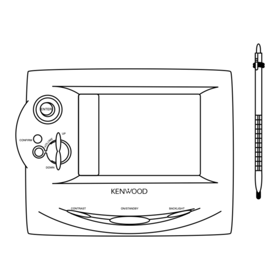
Page 13: Operation Of Graphcal Remote Control
Operation of Graphcal Remote Control Perform the following procedure after inserting batteries for the first time and every time after changing them. Loading the batteries Loading batteries 1 Remove the cover. 2 Insert batteries. Remote control operation 1 The touch screen responds to pressure from the included stylus or your finger. - Page 14 To adjust the contrast 1 Press the CONTRAST button until “Con- trast” message appears on the screen. 2 While this message is displayed, move ENTER the joystick up or down to increase or decrease the contrast until you are satis- fied.
-
Page 15: Setting Up The Grc According To Other Components (Set Up)
Setting up the GRC according to other components (Set Up) In the initial condition, the setup codes for CD, MD and DVD have already been pre-registered. The GRC can also be used to remote control other components which are not con- nected through system control cords. - Page 16 7 Press the “Code” icon. You can now choose from a list of all the codes available for the device. Select the first code on the list. 8 Press the “Check” icon. 9 Press the “Enter” icon. Set up other components in the same way as above. Programming remote control functions Remote control functions of some components may not be available even after the setup codes have been registered.
- Page 17 5 Repeat steps 2 through 4 until you have taught GRC all the commands you want it to know. If you need more lines, touch or to access more lines. Programming an additional function which is not dis- played in the screen 1 Repeat steps 1 and 2 in “To program STOP as a new control item”.
-
Page 18: Remote Control Of Components From The Grc
Remote control of components from the GRC Controlling the AV Control Center The operations required to remote control the AV Control Center includes the INPUT SELECTOR selection, display mode selection, stereo selection and so on. The following procedures show how to remote control the basic operations of the GRC. -
Page 19: Controlling The Components Connected Through System Control Cords
Controlling the components connected through system control cords When a CD player, MD recorder, cassette deck and/or DVD player are connected with the AV CONTROL CENTER through system control cords, their system control operations are possible from the GRC. Preparations ÷... - Page 20 Operating the cassette deck 1 Select the ”music“ icon in the fixed segment screen. (Select the icon) 2 Select the ”MD/TAPE 1“ icon. Display the cassette deck operation menu. 3 Select the icon to be operated. Select the ”movie“ icon in the Quick access menu. Operating the DVD player 1 Select the ”movie“...
- Page 21 Operating the TV Operating the CABLE Operating the SATELLITE Operating the LD player (Non Kenwood) Remote control of components from the GRC ÷ Any of the Video operation keys can be selected. ÷ For the operation of the Video cassette recorder, also read the...
-
Page 22: Convenient Functions
Convenient functions One-touch operation features (CD player, cassette deck (Single deck only), DVD player) When the system is in standby mode, the operations as de- scribed below are possible provided that the associated compo- nents are connected through system control cords. Preparations 1 Ensure that system control cords are connected. -
Page 23: Speaker Settings
Speaker settings Setup for surround play (SET UP) The feeling of presence in the surround effects can be improved by performing the following adjustment procedure according to the speaker system and listening room environment in use. Once they are adjusted, re-adjustment is not necessary even after the surround mode is switched to other modes. - Page 24 Select a speaker system. 1 Set up the subwoofer. “SW” (Select the icon) 2 Select On or Off. Each press changes the setup. 3 Set up the subwoofer remix. “Remix” (Select the icon) 4 Select On or Off. Each press changes the setup. 5 Set up the front speaker size.
- Page 25 Set the speaker distance. 1 Measure the distance from the listening position to each of the speakers. 2 Select a speaker distance. (Select the icon) 3 Set “SP Distance”. (Select the icon) To decrease 4 Touch to select the speaker. 5 Repeat steps 3 and 4 for each speaker.
- Page 26 3 Adjust the levels of all the speakers than the front speakers (left, right). While test tone is output from a speaker, adjust the volume level of the speaker. (Select the icon) To decrease level 4 Repeat 3 until all the system's speakers (except the subwoofer) play at the same volume.
-
Page 27: Playing Music
Playing music The following procedure allows to play a MD,CD or cassette tape. Preparations ÷ Connect components as described in “System connection”. ÷ Complete “Setup of the Graphical Remote Control (GRC) unit”. Press the ON/STANDBY key to ON. Main unit ON/STANDBY Select the input source. -
Page 28: To Listen Through Headphones
To listen through headphones 1 Plug headphones. PHONES 2 Adjust the volume. Main unit VOLUME CONTROL DOWN DOWN decrease increase volume volume To mute sound temporarily Notes for using the CD, DVD or DVD 6ch INPUT source When CD, DVD or DVD 6ch INPUT is selected as the input source, the operation is subjected to the following restrictions. Restrictions with CD and DVD: 1. -
Page 29: Sound Adjustment
Sound adjustment Ajustment for surround play Adjusting the tone (Stereo status only) 1 Enter the SOUND adjustment mode. (Select the icon) 2 Select the "Tone" icon. (Select the icon) To decrease 3 Touch to turn the tone setting on or off. - Page 30 2 Adjust the center speaker level. “C” (Select the icon) 3 Adjust to the desired level by pressing keys 4 Adjust the surround speaker level. “LS/ RS” (Select the icon) 5 Adjust to the desired level by pressing keys 6 Adjust the subwoofer level. “SW” (Select the icon) 7 Adjust to the desired level by pressing keys...
-
Page 31: Recording
Recording When recording sound with a recorder component of KENWOOD, synchro recording is possible by setting the INPUT SELECTOR to select MD or TAPE 1 according to the connected component. Sound may not be reproduced when the input signal and LISTEN MODE are selected improperly. - Page 32 Select the ANALOG input mode. Main unit 1 Set the input mode to ANALOG. INPUT MODE (Select the icon) Start recording. Main unit 1 Play the source to be recorded. 2 Press the “Dst.” icon. 3 Press the record key to enter record-pause mode.
-
Page 33: Recording A Digital Input Source (Cd,Dvd)
When recording sound with a recorder component of KENWOOD, synchro recording is possible by setting the INPUT SELECTOR to select MD or TAPE 1 according to the connected component. Sound may not be reproduced when the input signal and LISTEN MODE are selected improperly. - Page 34 Set the input mode to DIGITAL AUTO (MANUAL). Main unit 1 Set the input mode to “DIGITAL AUTO INPUT MODE (MANUAL)”. (Select the icon) Select the DIGITAL REC mode. AUTO REC MODE Main unit 1 Set the REC mode to “AUTO REC DIGITAL MODE”.
- Page 35 1 Select the ”edit“ icon in the fixed seg- ment screen. (Select the icon) 2 Select the source to be recorded. Select an input source other than MD/TAPE 1. 3 Select the “Distination”. 4 Press the “Src.” icon. 5 Set the REC mode to “Dig. Rec Mode.”. (Select the icon) 6 Play the source to be recorded.
- Page 36 Recording Start recording. Main unit 1 Press the “Src.” icon. 2 Pause the playing the source from begin- ning of the track being recorded. 3 Play the source and start recording.
- Page 37 Recording...
-
Page 38: Listening To Radio Broadcasts
Listening to radio broadcasts Radio stations can be classified into RDS (Radio Data Sys- tem) stations and other stations. For listening to RDS sta- tions or storing RDS stations in preset memory, see section entitled “Functions of RDS”. Tuning radio stations Select the TUNER input. -
Page 39: Functions Of Rds
Functions of RDS (Radio Data System) RDS is a system which transmits useful information (digital data) for FM broadcasts together with the broadcast signal. Tuners and receivers designed for RDS reception can extract the information from the broadcast signal for use with various functions such as automatic display of the station name. -
Page 40: Presetting Rds Stations (Auto Memory)
Use the operating procedure on this page to store RDS stations automatically in preset memory. Up to 40 RDS stations can be preset and received with a simple key operation. This unit is compatible with the RDS so it can use convenient RDS functions including automatic tuning and EON reserva- tion. -
Page 41: Storing Radio Stations Manually In Preset Memory
The AUTO MEMORY function gives precedence to RDS stations and assigns them from preset number 1. Therefore, when it is required to preset RDS stations as well as non-RDS stations, execute the AUTO MEMORY operation first then proceed to the manual memory operation of non-RDS sta- tions. -
Page 42: Receiving All Preset Stations In Order
9 Press the “Enter” icon to enter in memory. (Select the icon) 0 Press the “Enter” icon. Receiving all preset stations in order 1 Select the preset number of the desired station by pressing (Select the icon) The preset number decreases. -
Page 43: Searching For A Desired Program Type (Pty Search)
By specifying the type of program (genre) you want to listen to, the tuner automatically searches for a station which is currently broadcasting a program of the specified type. With certain receiving conditions, it may take more than 1 minute until the search completes. Preparation ÷... - Page 44 Start the search. Main unit (Select the icon) To change to a different program type: Repeat steps 1, 2, 3. To cancel search in the middle of it Main unit (Select the icon) Listening to radio broadcasts When searching for a Rock Music broadcast. Display while the tuner is searching.
-
Page 45: Reserving The Desired Information (Eon Reservation)
When the receiver is tuned to a RDS EON station (a station at which the EON indicator lights up), this function lets you set the receiver to automatically switch stations to receive news or traffic programs as they are broadcast. When the broadcast is over, the receiver returns to the original station automatically. -
Page 46: To Cancel Eon Reservation
Select the desired kind of program. Main unit (Select the icon) TA/NEWS Wait for a reserved reception to start. Leave the station with which the EON and RDS indicators light tuned in. The tuner stands by for the reception provided that the power is left ON. - Page 47 Listening to radio broadcasts...
-
Page 48: Ambience Effects
Ambience effects This AV CONTROL CENTER incorporates 7 different sound modes to let you enjoy surround sound with a wide variety of program sources. The Dolby Digital (AC-3) and Dolby Pro Logic surround sound let you enjoy theater-like surround effects when you play Dolby Digital (AC-3) and Dolby Surround program sources (like Laserdiscs and DVDs). -
Page 49: Dsp Mode
Dolby Pro Logic Dolby Pro Logic is a specially encoded 2 channel surround format designed to provide theater- like surround sound from Dolby Surround encoded sources (such as video and Laserdisc software marked ). This AV CONTROL CENTER is equipped with a Dolby Pro Logic surround decoder to let you enjoy the wide variety of currently available Dolby Surround home video software. -
Page 50: Surround Play (Listen Mode)
The DTS compatible models can reproduce a CD, DVD or LD carrying the DTS mark. Dolby Digital (AC-3) can be used when playing DVD or LD software bearing the and Dolby 3 Stereo can be used when playing video, DVD, or LD software bearing the with any source except Dolby Digital and DTS. - Page 51 Ambience effects c To select the Circle surround mode: (Select the icon) 1 Select the Circle surround type. (Select the icon) To end surround play Main unit 1 Select the “Stereo” icon. (Select the icon) LISTEN MODE...
-
Page 52: To Select The Dsp Mode (Dsp)
To select the DSP mode Select the DSP surround mode. 1 Select DSP. (Select the icon) 2 Select the “Arena” “Theater” “Jazz Club”. (Select the icon) Select the adjustment parameter. 1 Display the setup screen. To decrease 1 WALL TYPE Select “Soft”, “Medium”... -
Page 53: Listen Mode Selection
Listen mode selection Surround play of digital input INPUT selector Input signal 1 DTS 2 STEREO Listen mode Surround play of analog input INPUT selector Input signal Listen mode ÷ *1 : The possible selections may be limited depending on the played source and speaker setting. Checking the current status (Status) (Remote control only) 1 Select the “listen mode”... -
Page 54: Clock Adjustment
Clock adjustment This unit incorporates a clock function. Be sure to adjust the correct time before using the timer function. The time display blinks after a power failure or when the power cord has been unplugged from the AC outlet and plugged in again. -
Page 55: Timer Operation
Timer operation Two 24-hour timer systems (TIMER 1, TIMER 2) (which can be used every day) and a sleep timer system (which works only once) are available. In each of TIMER 1 and TIMER 2, the timer data including the operating period and played contents can be set and se- lected to be activated or not as required. - Page 56 Enter the On time (Minute). Main unit MULTI.CONTROL 1 Set the figure of minute. LEVEL To decrease To increase the figure the figure 2 Enter the figure in memory. TIMER Enter the OFF time (Hour). Main unit 1 Set the figure of hour. MULTI.CONTROL LEVEL To decrease...
-
Page 57: Activating The Timer
Make the desired reservation. For timer playback Main unit 1 Select the mode. 1 Select “PLAY” MULTI.CONTROL (Each press alternates them.) LEVEL PLAY : At the ON time, playback starts. Down P L A Y TIMER 2 Enter it. 2 Select the input source. 1 Select the source to be played. -
Page 58: Sleep Timer
Check the reservation content. Main unit TIMER MODE Select the TIMER number to be checked. When timer operation is not required Press so that all TIMER No. indicators are TIMER MODE To set the same timer program again TIMER MODE Press so that the desired TIMER No. - Page 59 Timer operation...
-
Page 60: Important Items
Important items Maintenance Maintenance of the unit When the front panel or case becomes dirty, wipe with a soft, dry cloth. Do not use thinner, benzine, alcohol, etc. for these agents may cause discoloration. In regard to contact cleaner Do not use contact cleaners because it could cause a malfunction. Be specially careful not to use contact cleaners containing oil, for they may deform the plastic component. -
Page 61: In Case Of Difficulty
In case of difficulty What appears to be a mulfunction may not always be serious. If your unit should not perform as expected, consult the table below to see if the problem can corrected before seeking help from your dealer or service representative. How to reset the microcomputer The microcomputer may malfunction (impossibility of opera- tion, erroneous display, etc.) when the power cord is unplugged... -
Page 62: Remote Control Unit
Remote control unit Symptom Remote control operation is not possible. The GRC screen is not displayed. Remote control operation is not available though the GRC screen is displayed. Cause ÷ Batteries are exhausted. ÷ The remote control unit is too far away from the main system, controlling angle is too large, or there is an obstacle in between. -
Page 63: Specifications
(30% mod., S/N 20 dB) ... 35 µV Signal to noise ratio (at 30% mod. 1mV input) ... 45 dB 1. KENWOOD follows a policy of continuous advancements in development. For reason specifications may be changed without notice. Notes Notes Notes 2. - Page 64 For your records Record the serial number, found on the back of the unit, in the spaces designated on the warranty card, and in the space provided below. Refer to the model and serial numbers whenever you call upon your dealer for information or service on this product.