Advertisement
Quick Links
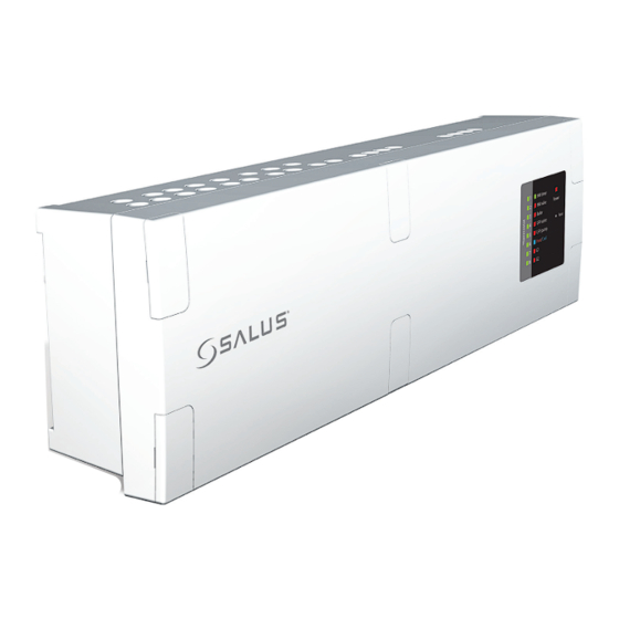
iT600 Wiring Centre KL10 005_Layout 1 05/06/2014 16:23 Page 1
HOT WATER TIMER
MODEL VS10W
8
+
2
1
SL L
N
OPTIONAL
1
2
1.5MM
CABLE
(INSTALLER SUPPLIED)
230V
2
1.5MM
CABLE
(INSTALLER SUPPLIED)
COLOURS ARE INDICATIVE ONLY.
EXTRA CONNECTIONS MAY BE REQUIRED
AS PER MANUFACTURERS INSTRUCTIONS
OPTIONAL
CYLINDER STAT
www.salus-controls.com Technical Helpline 00000 000000
ROOM THERMOSTAT PRT
THERMOSTAT
GROUP 2
MODEL VS10W
MODEL VS10W
THERMOSTAT
+
+
+
2
1
SL L
N
2
1
SL L
N
2
1
SL L
N
OPTIONAL
OPTIONAL
2
1.5MM
3 CORE
2
0.5MM
TWIN
FACTORY
FACTORY
FACTORY
FITTED
FITTED
FITTED
LINK
LINK
LINK
6
IN
OUT
BR EA N
OR GR
IN OUT
L
N
E
IN OUT
BR EA N
OR GR
IN OUT
HW CYLINDER
HW MOTORISED VALVE
OVERHEAT STAT
UFH PUMP
BOILER ENABLE
UFH MOTORISED VALVE
HEETING/
THERMOSTAT
COOLING
5
SL N
L
SL N
L
SL N
L
SL N
L
SL N
L
HOT WATER
ZONE 1
ZONE 2
ZONE 3
ZONE 4
L
N
L
N
L
N
L
N
L
N
L
N
L
N
L
N
L
7
ZONE 1
ZONE 2
ZONE 3
ZONE 4
SUPPLIED CABLES
UNDERFLOOR HEATING MANIFOLD
230V TO UFH PUMP
2
CABLE (INSTALLER SUPPLIED)
1.5MM
GROUP 2
GROUP 2
GROUP 1
THERMOSTAT
DIAL THERMOSTAT
DIAL THERMOSTAT
+
+
+
2
1
SL L
N
2
1
SL L
N
OPTIONAL
OPTIONAL
OPTIONAL
2
0.5MM
TWIN
2
1.5MM
3
5
SL N
L
SL N
L
SL
N
L
SL
N
L
+ + + +
-
-
-
-
+ + + +
ZONE 5
ZONE 6
ZONE 7
ZONE 8
GROUP 2
GROUP 1
N
L
N
L
N
L
N
L
N
L
N
L
N
L
N
ZONE 5
ZONE 6
ZONE 7
ZONE 8
2
CABLE (INSTALLER SUPPLIED)
1.5MM
2
OPTIONAL UFH ZONE VALVE
FOR RADIATORS GROUPS
Installation and wiring guide
GROUP 1 CONTROL
OPTIONAL
PRT (RADIATORS
THERMOSTAT
+
+
2
1
SL L
N
2
1
SL L
N
2
1
SL L
OPTIONAL
3 CORE
FUSE
4
FUSE
Meets the following EC Directives
• Electro-Magntic Compatibility directive 2004 / 108 / EC
• Low voltage Directive 2006/95/EC
2
1.5MM
CABLE
(INSTALLER SUPPLIED)
These instructions are applicable to the SALUS model
stated on the front cover of this manual only.
Warning
This product must be fitted by a competent person, and
installation must comply with the guidance, standards and
regulations applicable to the city, country or state where the
13 AMP FUSED CONNECTION UNIT
FUSED AT 3 AMPS
product is installed. Failure to comply with the requirements
of the relevant guidance, standards and regulations could lead
to injury, death or prosecution.
Warning
Always isolate the AC Mains supply before installing or working
on any components that require 230 VAC 50Hz supply.
For PDF Installation guide please go to www.salus-controls.com
Maintaining a policy of continued product development SALUS Controls plc reserve the right to change
specification, design and materials of products listed on this installation guide without prior notice.
Issue Date: June 2014 Document Number 00105
KL10
9
Advertisement

Related Manuals for Salus KL10


Summary of Contents for Salus KL10
- Page 1 For PDF Installation guide please go to www.salus-controls.com www.salus-controls.com Technical Helpline 00000 000000 Maintaining a policy of continued product development SALUS Controls plc reserve the right to change specification, design and materials of products listed on this installation guide without prior notice.
- Page 2 Wiring Centre KL10 005_Layout 1 05/06/2014 16:23 Page 2 KL10 Installation and wiring guide Hot Water Connections Ribbon Connection Motorised Valves, Pump, Boiler & Stat Connections OPTONAL HOT OPTONAL UPH WATER MOTORISED Optional Cylinder Thermostat: If connecting the cylinder thermostat...