Sharp AR-M455N Service Manual
Digital multifunctional system
Hide thumbs
Also See for AR-M455N:
- Operation manual (380 pages) ,
- Quick reference manual (31 pages) ,
- Software setup manual (21 pages)
Table of Contents
Advertisement
Quick Links
[1] GENERAL. . . . . . . . . . . . . . . . . . . . . . . . . . . . . . . . . . . . . . . . . . . . 1-1
[2] CONFIGURATION . . . . . . . . . . . . . . . . . . . . . . . . . . . . . . . . . . . . . 2-1
[3] SPECIFICATIONS . . . . . . . . . . . . . . . . . . . . . . . . . . . . . . . . . . . . . 3-1
[4] CONSUMABLE PARTS . . . . . . . . . . . . . . . . . . . . . . . . . . . . . . . . . 4-1
[5] EXTERNAL VIEWS AND INTERNAL STRUCTURES . . . . . . . . . . 5-1
[6] UNPACKING AND INSTALLATION . . . . . . . . . . . . . . . . . . . . . . . . 6-1
[7] MAINTENANCE AND DETAILS OF EACH SECTION . . . . . . . . . . 7-1
[8] ADJUSTMENTS . . . . . . . . . . . . . . . . . . . . . . . . . . . . . . . . . . . . . . . 8-1
[9] SIMULATIONS . . . . . . . . . . . . . . . . . . . . . . . . . . . . . . . . . . . . . . . . 9-1
[10] MACHINE OPERATION . . . . . . . . . . . . . . . . . . . . . . . . . . . . . . . . 10-1
[11] TROUBLE CODES . . . . . . . . . . . . . . . . . . . . . . . . . . . . . . . . . . . . 11-1
[12] ROM VERSION-UP METHOD . . . . . . . . . . . . . . . . . . . . . . . . . . . 12-1
[13] ELECTRICAL SECTION. . . . . . . . . . . . . . . . . . . . . . . . . . . . . . . . 13-1
Parts marked with "
" are important for maintaining the safety of the set. Be sure to replace these parts with
specified ones for maintaining the safety and performance of the set.
SERVICE MANUAL
DIGITAL MULTIFUNCTIONAL
SYSTEM
MODEL
CONTENTS
SHARP CORPORATION
CODE: 00ZARM455NA1E
AR-M355N
AR-M455N
This document has been published to be used
for after sales service only.
The contents are subject to change without notice.
Advertisement
Table of Contents

Related Manuals for Sharp AR-M455N


Summary of Contents for Sharp AR-M455N
-
Page 1: Service Manual
DIGITAL MULTIFUNCTIONAL SYSTEM AR-M355N AR-M455N MODEL CONTENTS [1] GENERAL..........1-1 [2] CONFIGURATION . -
Page 2: Cautions On Laser
CAUTION Cautions on laser +10 nm At the production line, the output power of the scanner unit 785 nm Wave length −15 nm is adjusted to 0.4 MILLIWATT PLUS 8 % and is maintained constant by the operation of the Automatic Power Control (APC). North America: Pulse times 35 cpm model: (6.2 µs ±... -
Page 3: Table Of Contents
CONTENTS [1] GENERAL [6] UNPACKING AND INSTALLATION Note for servicing ......1-1 Installing procedure flowchart ....6-1 A. -
Page 4: Table Of Contents
[8] ADJUSTMENTS [12] ROM VERSION-UP METHOD Process section ......8-1 General ........12-1 A. -
Page 5: General
[1] GENERAL 1. Note for servicing Pictogram This Service Manual uses some pictographs to assure safe opera- tion. Please understand the meanings of pictographs before servicing. CAUTION: If this CAUTION is ignored, an injury or damage to property could occur. A. -
Page 6: Configuration
[2] CONFIGURATION 1. System configuration A. Basic system AR-M355N/M455N (Copier/Network printer model) Necessary options • Any one of the stand/MPD & 2000 sheet paper drawer (AR- D28), the stand/3 x 500 sheet paper drawer (AR-D27), or the multi purpose drawer (AR-MU2)* •... -
Page 7: B. Option Lineup
B. Option lineup For combinations of options, refer to "C. List of combination of peripheral devices" described later. (1) Major options 10. Finisher (AR-FN6) 6. Exit tray 7. Duplex (AR-TE3) module/bypass tray 5. Right upper exit (AR-DU4) tray (AR-TE5) 4. Upper exit tray (AR-TE4) 8. - Page 8 Option name Installing conditions Stand/MPD & 2000 sheet paper drawer AR-D28 • Simultaneous installation with the large capacity paper feed desk (AR-D28) or the 3-stage paper feed desk (AR-D27) is Stand/3 x 500 sheet paper drawer AR-D27 inhibited. Multi purpose drawer AR-MU2 Upper exit tray extension AR-TE4...
-
Page 9: C. List Of Combination Of Peripheral Devices
C. List of combination of peripheral devices As shown in the table below, some other peripheral devices ( B ) may be needed for installation of a peripheral device ( A ) and some peripheral devices cannot be installed together. Related to paper feed unit Multi purpose drawer AR-MU2... -
Page 10: Specifications
1. Basic Specification A. Base Engine (1) Form Console type Japanese postcard (2) Engine speed Ledger Legal Paper size AR-M355N AR-M455N Foolscap A4, 8.5" x 11" 35ppm (31ppm*) 45ppm (40ppm*) Letter A4R, 8.5" x 11"R 25ppm 30ppm Executive A5R/5.5" x 8.5"R, Invoice-R... -
Page 11: B. Document Feeding Equipment
B. Document Feeding Equipment (2) Support OS (1) One-drawer tray (included in the base engine) Custom PS Windows 95/98/Me Windows NT 4.0 Paper feed method One-drawer tray Windows 2003 server Sizes to be fed A4, B5, 8.5" x 11" Windows 2000 server Paper capacity 500 sheets (at 80g/m²) Windows 2000... - Page 12 b. Paper Input d. Graphic PPD file *1 PPD file *1 Function PCL5e PCL6 Function PCL5e PCL6 (for Windows (for Windows XP) Paper size A3 / B4 / A4 / B5 / Resolution 600/300 dpi 600dpi 600dpi A5 / Ledger / setting Legal / Foolscap / Letter / Executive...
- Page 13 (5) Macintosh driver functions c. Paper output Macintosh PPD file a. General Function (for Mac OS X ver10.2.8) Macintosh PPD file Function Output tray Center tray (for Mac OS X ver10.2.8) selection Finisher Copies 1-999 • Top tray Orientation Portrait •...
-
Page 14: B. Image Send Function
f. Others B. Image send function Macintosh PPD file (1) Mode Function (for Mac OS X ver10.2.8) Scanner (Scan to E-mail, Scan to Sharpdesk, Scan to FTP, Scan Configuration setting to HDD), FAX, Internet FAX Watermark (2) Support system Form overlay –... - Page 15 (6) Specified multiple destinations Internet Mode Scanner Mode Scanner Internet FAX – Receive Auto receive Specified Specifying by one-touch or group, manual function – Manual receive destination destination entry. – Memory receive Max. number Total of 5000 destinations including group and –...
-
Page 16: C. Copy Function
(8) Transmission method (3) Job speed Mode Scanner Internet FAX AR-M355N AR-M455N Transmission time – 2 seconds (level: S→ S 33 cpm (94%) 42 cpm (93%) Super G3/JBIG) S→ D 32 cpm (91%) 40 cpm (88%) 6 seconds (G3 D→ D... -
Page 17: B/W Scanner Module (Dspf)
3. B/W Scanner Module (DSPF) Special Margin shift function Edge erase/Center erase (1) Form Dual page copying Scanner (Document glass) / DSPF standard Covers/Inserts Operation panel integral type Transparency insert (common hardware for all the destinations) Centering (2) Resolution / Gradation Multi shot (Nin1) Yes (2 in 1 / 4 in 1) Reading resolution (dpi) -
Page 18: Rack For Scanner
OR guide Rear left side Original reference position " " Original tray Center of the tray Original reference position display (Print display) guide (inscribed symbol) " " Original face-down display placement indication " " Left side OR (From the Interior side) guide 5-1/2, A5R, B5R, A4R/A5, Original Guide... -
Page 19: Consumable Parts
[4] CONSUMABLE PARTS 1. Supply system table A. USA/Canada Item Content Life Model name Remarks Toner cartridge (Black) Toner cartridge (with IC) x 10 350K AR-455MT *Life setup is based on A4 6% (Toner : Net weight 750 g) (35K x 10) Developer (Black) Developer x 10... -
Page 20: Production Number Identification
3. Production number identification C. Developer cartridge The lot number is of 8 digit, and each digit indicates as follows. A. Drum cartridge The lot number shall be printed on the bag. The lot number, printed on the front side flange, is composed of 10 digits, each digit showing the following content: Alphabet Indicates the production factory. -
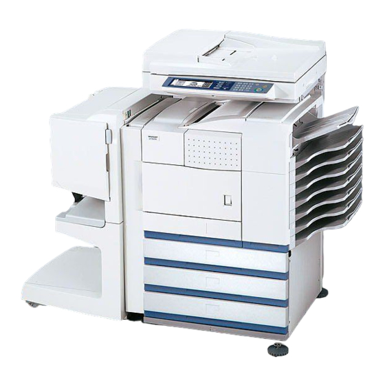
Page 21: External Views And Internal Structures
[5] EXTERNAL VIEWS AND INTERNAL STRUCTURES 1. Exterior Name Function Note Bypass tray This tray can also be used for special papers including Option transparency film. (AR-DU4) Exit tray The tray is extendable to support large size paper. Extend the tray Option when 11"... -
Page 22: Interior
2. Interior Name Function Duplex module side cover Open when a misfeed has occurred in the duplex module. Side cover latch Push up to open the side cover when a misfeed has occurred in the main unit. Fusing unit Lift up to open the side cover when a misfeed has occurred in the main unit. CAUTION: The fusing unit is hot. -
Page 23: Operation Panel
3. Operation panel Name Function Touch panel The machine status, messages and touch keys are displayed on the panel. The document filing, copy, network scanner* , and fax* functions are used by switching to the screen for the desired function. Mode select keys and indicators Use to change modes and the corresponding display on the touch panel. -
Page 24: Job Status Screen (Common To Print, Copy, Fax Network Scan And Internet Fax)
4. Job status screen (common to print, copy, fax, network scan and Internet fax) This screen is displayed when the [JOB STATUS] key on the operation panel is pressed. This screen can be used to display the "JOB QUEUE" (showing stored jobs and the current job) or the "COMPLETE" job list (showing fin- ished jobs). -
Page 25: Cross Sectional View
5. Cross sectional view A. Scanner unit 3 SPPD 4 SPED 17 SPOD Name Name CIS unit Copy lamp base unit Original resist roller No. 1 mirror Original resist front sensor (SPPD) Copy lamp (Xenon) Original set sensor (SPED) Mirror base unit Original take-up sensor No. -
Page 26: Switch, Sensor
6. Switch, Sensor A. Scanner unit Code Name Active condition SPPD SPF original resist front sensor SCOV SPF paper feed cover sensor SPED SPF original set sensor OCSW OC open/close sensor ORS-LED Original size sensor PWB (Light emitting side) SPLS1 SPF original length sensor 1 SPLS2 SPF original length sensor... -
Page 27: A. Scanner Unit
7. PWB A. Scanner unit Name Function/Operation SPF control PWB SPF control Original size detection PWB (Light emitting side) Original size detection when using the table glass CCD PWB (in lens unit) (The lens unit cannot be disassembled.) Image scan (Table glass/SPF surface) SPF original width detection volume PWB SPF original width detection MFP operation PWB... -
Page 28: Motor, Clutch, Solenoid
8. Motor, Clutch, Solenoid A. Scanner unit Name Function/Operation SPFM SPF motor Original transport in SPF scan SRRC SPF original resist clutch SPF original scan timing adjustment SPFC SPF original feed clutch SPF original feed roller drive SDSS SPF original stopper solenoid SPF original stopper gate drive MIRM Mirror motor... -
Page 29: Unpacking And Installation
[6] UNPACKING AND INSTALLATION 1. Installing procedure flowchart There are many combinations between this machine and option units. For installing option units, observe the following procedures for efficiency. To install the devices effciently, follow the procedure below. Some peripheral devices may have been installed as standard devices depending on the main unit model. -
Page 30: Note For Installation Place
2. Note for installation place 3. Unpacking procedure Improper installation may damage this product. Please note the following during initial installation and whenever the machine is moved. 1) The machine should be installed near an accessible power outlet for easy connection. 2) Be sure to connect the power cord only to a power outlet that meets the specified voltage and current requirements. -
Page 31: Machine Installing Procedure
4. Machine installing procedure 3) Remove the top cover of the developer cartridge. Note: In advance to installation of the machine, the paper feed option units (AR-D27/AR-D28/AR-MU2) should have been installed. A. Remove the locking tape 4) While rotating the MG roller, supply developer into the devel- oper cartridge evenly. -
Page 32: D. Setting Related To Fusing
2) Insert a new toner cartridge. E. Paper setting Push the cartridge in until it locks securely into place. 1) Pull out the first stage paper feed tray. Slowly pull out the tray until it stops. 3) Gently remove the sealing tape from the cartridge. 2) While pressing the paper holding plate, remove the fixing pin. -
Page 33: Automatic Developer Adjustment
5. Automatic developer adjustment 7. Attach the document scanning label 1) Attach the cabinets which were removed. Reference 2) Close the left door. At that time, keep the front door open. Reference Note: The automatic developer adjustment must be performed by entering the simulation mode with the front door open. - Page 34 2) Insert the handle into the left rack notch diagonally upward as shown in the figure. 3) Attach the screw which was removed in procedure 1) to secure the handle. 4) Lift the rear edge of the handle to engage the head with the rack.
-
Page 35: Maintenance And Details Of Each Section
[7] MAINTENANCE AND DETAILS OF EACH SECTION • Self print of set values • When assembling, check that the flat cable and the harness connectors are securely connected. Use of SIM 22-6 allows to print the set values and the jam his- tory of the machine. -
Page 36: Scanner / Dspf
2. Scanner / DSPF Maintenance cycle : 200K ✕ Check (Clean, replace, or adjust as necessary.) ❍ Clean L Replace ∆ Adjust ✩ Lubricate ❏ Move position When Unit name Part name 100K 200K 300K 400K 500K 600K 700K 800K Remark calling ❍... -
Page 37: Peripheral Devices
3. Peripheral devices Maintenance cycle : 50K ✕ Check (Clean, replace, or adjust as necessary.) ❍ Clean L Replace ∆ Adjust ✩ Lubricate ❏ Move position When Option name Part name 100K 200K 300K 400K 500K 600K 700K 800K Remark calling ❍... -
Page 38: Details Of Each Section]
[DETAILS OF EACH SECTION] 1. Process section A. General Toner is attached to electrostatic latent images formed by the laser beams which were radiated to the OPC drum charged by the main charger, forming toner images. The toner images formed on the OPC drum are transferred to paper by the transfer roller. - Page 39 Process Section Composition and Applying Voltage MAX 8KV constant current opc27 m ctc27 m Separation electrode -1.8KV -650V 11 10 (-620V) -800V 25µA (45ppm) 19µA (31/35ppm) MAX 5KV Toner density sensor Paper dust cleaner 200M 200M Temperature/humidity sensor -500V (-470) Composition of process section Laser beam Forms latent electrostatic images on the photoconductor drum.
-
Page 40: Opc Drum Section]
[OPC drum section] A. General In this section, laser beams are radiated to the OPC drum surface which was negatively charged, making electrostatic latent images. B. Major parts and signal functions 8FE-BT-VK-N DSW-L DSW-L GND1 GND1 DM-T DMCLK\ (NC) PHNR-02-H+BU02P-TR-P-H PSPS\ PSPS +24V1... - Page 41 C. Operational descriptions 3) After transfer operation, remaining toner is removed by the cleaning blade. The OPC drum surface is negatively charged by the main charger. The laser beam images are radiated to the OPC drum surface by the laser unit to form latent electrostatic images. 1) The OPC drum surface is negatively charged by the main charger.
- Page 42 D. Maintenance and parts replacement (1) Maintenance list When Unit name Part name 100K 200K 300K 400K 500K 600K 700K 800K Remark calling ✕ ✕ ✕ ✕ Drum Drum Replace at 200K or 1 year. ❍ ❍ ❍ ❍ ❍ ❍...
- Page 43 ∗ When installing, install the DSD collar R to the drum frame, then a-1. MC unit install the drum and the DSD collar F. When installing the DSD 1) Remove the drum cartridge. collar, engage the DSD collar boss with the drum frame hole. 2) Check to confirm that the cleaning unit is inserted fully to the bottom.
- Page 44 ∗ When attaching the side molts F/R, attach them to the attach- a-6. Cleaner blade ment reference as shown. 1) Remove the drum cartridge. ∗ After attaching the side molt F/R, push the both ends of the 2) Remove the drum and the DSD collar. blade with your fingers to check to confirm that the red moquette 3) Pull it out until the cleaning unit stops.
-
Page 45: Transfer Section]
2) Remove the connector and the screw, and remove the PCU 3) Remove the screw and the connector, and remove the sepa- PWB unit. ration solenoid unit. 4) Remove the E-ring and the screw, and remove the separation solenoid. [Transfer section] A. - Page 46 8FE-BT-VK-N DSW-L DSW-L GND1 GND1 DM-T DMCLK\ (NC) CN15 1-84432-4(AMP) 9604S-14F DSW-F DSW-F SRA-21T-4L PS-187 GND2 GND2 9604S-08C GND2 GND2 SRA-21T-3 PS-187 DSW-F DHVREM DHVREM DSW-F MHVREM\ MHVREM\ GND2 THV+PWM\ THV+PWM\ SRA-21T-4L PS-187 GND2 GBPWM\ GBPWM\ PCU PWB DHVPWM\ DHVPWM\ SRA-21T-3 DM-T THV-PWM\...
- Page 47 C. Operational descriptions 2) Transfer roller cleaning After completion of the job, the applied voltage to the transfer 1) Toner image transfer roller is switched to negative in order to attract toner from the Toner images formed on the drum by the developing roller are transfer roller to the OPC drum, cleaning the drum with the transferred to paper by the transfer roller.
- Page 48 D. Maintenance and parts replacement (1) Maintenance list When Unit name Part name 100K 200K 300K 400K 500K 600K 700K 800K Remark calling ✕ ✕ ✕ ✕ ✕ Transfer Transfer roller ✕ ✕ ✕ ✕ ✕ Discharge plate ✕ ✕ ✕...
- Page 49 a-2. Discharge plate 1) Remove the transfer roller unit. 2) Remove the screw, and remove the discharge plate holder and the discharge plate. a-3. Transfer roller a-4. Transfer roller collar a-5. TR bearing (F/R) a-6. TR gear 1) Remove the transfer roller unit. 2) Remove the screw, and remove the discharge plate holder and the discharge plate.
-
Page 50: Developing Section]
[Developing section] A. General In this section, toner is attached to electrostatic latent images formed by laser beams on the OPC drum, making visible images. B. Major parts and signal functions 9604S-08C DSW-F DSW-F GND2 GND2 DM-T DMCLK\ (NC) HUS-DV 173981-2 TH-DV B8B-PH-K-S... - Page 51 C. Operational descriptions Electrostatic latent images formed on the OPC drum by the LED (writing) unit (LED image light) are converted into visible images by toner. layer Aluminum Drum -500V (-470V) Toner in the developing unit is stirred by the mixing roller. When toner is stirred, it is negatively charged by mechanical fric- tion.
- Page 52 D. Maintenance and parts replacement (1) Maintenance list When Unit name Part name 100K 200K 300K 400K 500K 600K 700K 800K Remark calling Developing Developer Supplied when installing ✕ ✕ ✕ ✕ section DV blade ✕ ✕ ✕ ✕ DV side seal F ✕...
- Page 53 ∗ When attaching the DV blade, attach to the attachment refer- a-1. Developer ence shown in the figure below. 1) Remove the DV cartridge. 2) Remove the screw, and remove the DV cover. Reference (Step) 0.5mm 0.5mm Reference a-3. DV side seal F a-4.
- Page 54 a-5. Toner density sensor a-8. Toner motor 1) Remove the toner cartridge. a-6. Humidity sensor 2) Remove the screw, and remove the rear cabinet. 1) Remove the DV cartridge. 2) Remove the bottom cover. 3) Remove the bottom cover. 4) Remove the screw and the connector, and remove the humid- 2) Remove the connector and the screw, and remove the PCU ity sensor.
-
Page 55: Fusing Section
2. Fusing section A. General This section fused toner (which is transferred onto paper in the transfer section) onto paper by heat and pressure of the fusing roller. Paper Fusing Copy exit Fusing roller Fusing roller Cleaning (Pressing) roller (Heating) Paper exit Main Heater lamps... - Page 56 Signal Active Code Name Type Function/Operation Note name condition RTH1 RTH1 Fusing temperature Thermistor Detects the surface temperature of the fusing roller Analog input sensor (1) (heating). (Center section) RTH2 RTH2 Fusing temperature Thermistor Detects the surface temperature of the fusing roller Analog input sensor (2) (heating).
- Page 57 In addition, the fusing temperature is switched according to the kind of paper. Fusing roller Mode AR-M355N AR-M455N Ready condition Plain paper 190°C 190°C print mode Heavy Paper 190°C...
- Page 58 (2) Maintenance and parts replacement 3) Pull the fusing lever, and remove the fusing unit. Unit Parts ❍ Fusing unit Lower separation pawl ❍ Upper separation pawl ✕ Thermistor ✕ Lower heat roller ✕ CL roller ✕ CL roller bearing Heater lamp ✕...
- Page 59 a-3. Thermistor a-5. CL roller 1) Remove the fusing unit. a-6. CL roller bearing 2) Remove the screw, and remove the fusing drawer. Remove 1) Remove the fusing unit. the connector. 2) Remove the lower heat roller. 3) Remove the screw, and remove the thermistor. 3) Remove the CL roller, and remove the CL roller bearing.
-
Page 60: Paper Feed Section
3. Paper feed section a-8. Upper heat roller a-9. Upper heat roller gear 1) Remove the fusing unit. 2) Open the fusing unit. 3) Remove the fusing rear upper PG. 4) Remove the heater lamp. 5) Remove the upper heat roller, the roller stopper. The upper heat roller gear, and the upper heat roller bearing. - Page 61 B. Major parts and signal functions CSS PWB 173979-2 173979-2 S4B-PH-K-S LUMB LUMB LUMA LUMA GND2 LUMB LUMA 179228-3(AMP) +5V2 GND2 179228-3(AMP) +5V2 CPFC GND2 PHNR-02-H+BU02P-TR-P-H CPFC\ +24V1 CN13 PHNR-09-H+BU09P-TR-P-H B24B-PHDSS-B GND2 +5V2 +24V1 PPD1 PCU PWB GND2 CPFC\ +5V2 +5V2 +24V1 GND2...
- Page 62 Name Function Remark 1 Take-up roller Picks up paper and transports it to the paper feed roller. 2 Paper feed roller Feed paper in the machine. 3 Separation roller Rotates simultaneously with the paper feed roller to prevent against overlapped feed. For the manual feed tray, the separation pad is used instead of the roller.
- Page 63 (3) Paper detection method of each tray 1) Machine 1st tray Paper detection is performed by VR in linkage with both side guides. 2) Multi-purpose tray Paper detection is performed by VR in linkage with both side guides and the detector in linkage with the rear edge plate. Width detection Vertical detection Paper size...
- Page 64 [Paper remaining quantity detection] (1) Paper remaining quantity detection Paper remaining quantity detection is common in each tray except for the manual feed tray. Remaining quantity is indicated in 3 steps plus paper empty (4 steps in total). (2) Detection method Paper remaining quantity is detected by the number of times of changing of the remaining quantity sensor from when the tray starts lifting up to when the upper limit sensor turns on.
- Page 65 D. Maintenance and parts replacement (1) Maintenance list When Unit name Part name 100K 200K 300K 400K 500K 600K 700K 800K Remark calling ✕ ✕ ✕ ✕ ✕ ✕ ✕ ✕ ✕ Paper feed Pick-up roller Note 1 ✕ ✕ ✕...
- Page 66 3) Disengage the pawl, and remove the pickup roller and the a-7. Cassette detection PWB paper feed roller. 1) Remove the screw, and remove the rear cabinet. 4) Disengage the pawl, and remove the separation roller and the torque limiter. 2) Remove the connector, and remove the cassette detection PWB.
-
Page 67: Transport Section/Paper Exit Reverse Section
4. Transport section/Paper exit reverse 3) Remove the E-ring, the gear, and the spring. 4) Remove the screw, and remove the lift-up motor. section A. General In this paper transport section, paper fed from each paper feed port is transported to the resist roller section, where the lead edge of the paper is aligned with the lead edge of images on the OPC drum. - Page 68 B. Major parts and signal functions SMR-06V+SMP-06V-NC /POMXA /POMA /POMB /POMXB +24V1 +24V1 SMP-03V-BC+SMR-03V-B 179228-3 POD1 POD1 GND2 GND2 +5V2 +5V2 179228-3 +5V2 POD2 GND2 179228-3 +5V2 POD3 B32B-PHDSS-B GND2 /POMXB +5V2 /POMB DSW-L SFPS-41T-187 POD1 /POMA POD3 GND2 /POMXA PHNR-03-H+BU03P-TR-P-H +5V2 POD2...
- Page 69 Signal Code Name Function/Operation Type Note name Resist roller clutch Resist roller ON/OFF control Electromagnetic clutch Paper transport roller clutch Paper transport roller ON/OFF control Electromagnetic clutch Main motor Drives the paper transport and resist roller DC brushless Paper pass motor Name Function...
- Page 70 Paper transport in duplex printing (with AR-DU3/DU4 installed) (1) Switchback operation and paper exit to the left tray 1) Paper transported from the fusing section is sent to the paper exit section of the machine. 2) When the male bin stacker (AR-MS1) or the finisher (AR-FN5) is installed, the paper entry gate solenoid (FGS) selects the paper entry gate to discharge paper outside the machine.
- Page 71 D. Maintenance and parts replacement (1) Maintenance list When Unit name Part name 100K 200K 300K 400K 500K 600K 700K 800K Remark calling ✕ ❍ ❍ ❍ ❍ ❍ ❍ ❍ ❍ Transport Resist roller ✕ ❍ ❍ ❍ ❍ ❍...
- Page 72 a-1. Paper dust remover unit b-1. Resist roller 1) Open the front door. 1) Remove the paper dust cleaner unit. 2) Remove the resist roller unit. 3) Remove the parts, and remove the resist roller. 4) Remove the gear, the parallel pin, and the E-ring. 2) Remove the paper dust cleaner unit.
- Page 73 4) Remove the screw and the connector, and remove the paper 3) Remove the connector, the screw, and the washer, and transport detector. remove the suction fan motor. 5) Remove the screw and the earth wire, and remove the high 4) Remove the screw, and remove the high voltage resistor voltage resistor PWB.
- Page 74 d. Paper exit reverse unit 6) Remove the screw, and remove the paper exit tray cabinet. 1) Pull out the left door. 7) Remove the screw, and remove the front right upper cabinet. 8) Remove the front door. 2) Remove the screw, and remove the rear cabinet. 9) Remove the E-ring and the parts.
- Page 75 d-2. Paper exit motor 4) Remove the connector, the exhaust heat fan, the paper exit detection 2, the paper exit full detection. 1) Remove the paper exit reverse unit. 2) Remove the connector and the screw, and remove the paper exit motor.
- Page 76 d-8. Paper exit roller 1) Remove the paper exit reverse unit. 2) Remove the screw, and remove the paper exit upper paper guide unit. 3) Remove the E-ring, and remove the paper exit roller. Remove the bearing, the gear, and the parallel pin. AR-M355N/M455N MAINTENANCE AND DETAILS OF EACH SECTION 7 - 42...
-
Page 77: Laser Scanner Section
5. Laser scanner section A. General Image data sent from the MFP (image process circuit) through the mother board and PCU are converted into laser beams to radiate onto the drum surface. B. Major parts and signal functions MOTHER SLD30R-1 CN16 BOARD CONTROL... - Page 78 Name Function Laser control PWB Controls laser beam flashing and the output value. Cylindrical lens Converges laser beams to focus. Incidence reflection mirror Assures the optical path for laser beams. No. 1 mirror Assures the optical path for laser beams. fθ...
- Page 79 4) Remove the screw, and remove the rear cabinet. 8) Remove the screw, and remove the main switch mounting plate. 9) Remove the power unit. 5) Remove the connector, the screw, and the angle. Remove the snap band. ∗ Do not disconnect the LSU side. 10) Remove the connector and the screw, and remove the duct holding cover.
-
Page 80: Scanner Section
6. Scanner section A. General There are following three methods of scanning documents in this machine. a. Place a document on the table glass. The copy lamp unit is operated to radiate copy lamp light onto the document, scan- ning the document with the CCD. b. - Page 81 B. Major parts and signal functions CCD PWB MHPS IL-FPR-40S-VF-E1500 TX25-100P-LT-H1 TX24-100R-LT-H1 S5B-PH-K-S GND2 MIMA GND2 MIMB GND2 /MIMA GND2 /MIMB 1_DATA1+ +24V3 1_DATA1- GND2 1_DATA0+ 1_DATA0- GND2 1_CLK+ 1_CLK- GND2 /1_DBL+ /1_DBL- GND2 FRM_CCD1 PAGE1 CLK_CCD1 ADD_CCD1 TXD_CCD1 RXD_CCD1 RES_CCD1 GND2 +3.3V3...
- Page 82 Name Function Copy lamp unit Lights up to radiate documents. A xenon lamp (operating on 3.15KV) is employed. Reflector This mirror converges lights on documents. No. 1 mirror Secures the optical path between a document and No. 2 mirror. No. 2 mirror Secures the optical path between No.
- Page 83 (3) Image signal flow (4) Carriage (lamp unit) shift (scan) speed The image signal converted into electric energy (analog signal) is The carriage scan speed depends on the copy magnification ratio. A-D converted on the CCD PWB. Image processes such as white Speed up to 171% = 110mm/s balance and shading correction are performed on the scanner Speed of 172% - 400% = 55mm/s...
- Page 84 D. Maintenance and parts replacement (1) Maintenance list When Unit name Part name 100K 200K 300K 400K 500K 600K 700K 800K Remark calling ❍ ❍ ❍ ❍ ❍ ❍ ❍ ❍ ❍ Scanner Mirror/Lens/Reflector/Sensors ❍ ❍ ❍ ❍ ❍ ❍ ❍...
- Page 85 a. Scanner unit a-6. Rails 1) Remove the table glass. a-1. OC 1) Remove the OC cover. 2) Grease up the rails. a-7. Drive wire a-8. Pulley a-2. Dust-proof glass a-9. Drive belt a-3. Table glass 1) Remove the table glass. a-4.
- Page 86 2) Pull out the harness from the scanner control PWB. a-14. Scanner interface PWB 3) Remove the scan motor. 1) Remove the table glass. 2) Remove the PWB cover and the harness cover. a-11. OC open sensor 3) Remove the scanner interface PWB. 1) Remove the rear cabinet.
- Page 87 b-1. Reflector b-4. Inverter PWB 1) Remove the table glass. b-1. Mirror 2) Hold with your hand and remove the screw. Remove the con- 1) Remove the table glass. nector and remove the inverter PWB. 2) Clean the reflector and the mirror. b-3.
-
Page 88: Dspf Section
4) Clean the CCD lens and the CCD. Note for CCD lens PWB unit installation <1> Adjust the CCD unit adjustment value listed in the table below with the scribed line on the lens base. CCD unit adjustment value (+) direction Reference line (-) direction 1 scale: 1.4mm... - Page 89 B. Major parts and signal functions SCOV OCSW SDSS SPLS2 SPED SPLS1 SPFS SPFVR SPPD SPFM SPFC SRRC STMP SPOD CIS unit SOCD TX24-100R-LT-H1 TX25-100P-LT-H1 CN10 S28B-PHDSS PHNR-6-H+BU6P-TR-P-H B26B-PHDSS-B B6B-PH-K-S 9604S-35F +24V3 +24V3 VLED +24V3 +24V3 +24V3 +24V3 DGND GND2 GND2 GND2 GND2...
- Page 90 Signal Code Name Function/Operation Type Note name SCOV SCOV SPF cover switch SPF cover open/close detection Transmission type Sensor SPFM SPFM1 SPF paper feed motor, paper Drives the paper feed roller and the Stepping motor transport motor transport roller. (SPF) SPFC SPFC SPF paper feed clutch...
- Page 91 D. Maintenance and parts replacement (1) Maintenance list When Unit name Part name 100K 200K 300K 400K 500K 600K 700K 800K Remark calling ❍ ❍ ❍ ❍ ❍ ❍ ❍ ❍ ❍ DSPF Pick-up roller Note 2 ❍ ❍ ❍ ❍...
- Page 92 a. SPF unit 2) Remove the stopper solenoid. 1) Remove the rear cabinet of the scanner section. 2) Disconnect the connector. 3) Disconnect the grounding wire. a-2. SPF document resist front sensor a-3. SPF paper feed cover sensor a-4. SPF document set sensor AR-EF3 1) Remove the upper transport unit cover.
- Page 93 a-6. SPF original length sensor 1 (SPF original width detection volume installation) <1> Extend the original guide to the maximum position. a-7. SPF original length sensor 2 <2> Adjust so that the mark on the width detection pinion gear is 1) Remove the OC cover.
- Page 94 a-11. CIS unit a-13. SPF open sensor 1) Remove the open sensor. a-12. CIS control PWB 1) Remove the upper transport unit cover. 2) Remove the CIS unit. a-14. SPF original exit sensor 1) Remove the paper exit sensor. ∗ When the CIS unit is replaced, the CIS shading adjustment must be performed.
- Page 95 a-16. SPF motor 5) Remove the SPF motor. 1) Remove the OC cover. 2) Remove the SPF lower cover. a-17. Resist roller a-18. Resist roller clutch 1) Remove the SPF resist roller unit. 3) Remove the original paper feed unit. 2) Remove the SPF resist roller and the SPF resist roller clutch.
-
Page 96: Operation Panel Section
a-19. SPF original paper feed solenoid a-21. Separation mylar lower a-20. SPF original paper feed clutch a-22. Separation pad 1) Remove the SPF paper feed unit. 1) Remove the upper transport unit. 2) Remove the SPF paper guide. 2) Loosen the screw, and remove the separation pad unit. 3) Remove the screw, and remove the separation plate and the front separation plate. - Page 97 B. Major parts and signal functions ORSLED OCSW ORS PD /CCFT TOUCH TX25-100P-LT-H1 BOARD TO BOARD TX24-100R-LT-H1 GND2 GND2 GND2 GND2 /1_DBL- /1_DBL- /1_DBL+ /1_DBL+ 1_CLK- 1_CLK- 1_CLK+ 1_CLK+ 1_DATA0- 1_DATA0- 1_DATA0+ 1_DATA0+ 1_DATA1- 1_DATA1- 1_DATA1+ 1_DATA1+ GND2 GND2 GND2 GND2 GND2 GND2...
- Page 98 Signal Code Name Function/Operation Type Note name LCD unit Display the each memu and the information. TOUCH Touch panel Various adjustments and setting operation are performed. ORSLED Document size detection light Generates the document size detection signal. emitting PWB ORSPD Document size detection light Generates the document size detection signal.
- Page 99 2) Remove the scanner left cabinet. b-1. LVDS PWB 1) Remove the operation panel unit. 2) Remove the connector and the screw, and remove the LVDS PWB. 3) Remove the scanner right cabinet. b-2. MFP operation PWB 1) Remove the operation panel unit. 2) Remove the MFP operation PWB 4) Remove the operation panel lower cabinet.
-
Page 100: Filter
9. Filter A. Maintenance and parts replacement (1) Maintenance list When Unit name Part name 100K 200K 300K 400K 500K 600K 700K 800K Remark calling Filters Ozone filter (2) Maintenance and parts replacement Unit Parts Ozone filter a-1. Ozone filter 1) Remove the paper exit tray cabinet cover, and remove the ozone filter. -
Page 101: Drive Section
10. Drive section A. Maintenance and parts replacement (1) Maintenance list When Unit name Part name 100K 200K 300K 400K 500K 600K 700K 800K Remark calling ✕ ✩ ✩ ✩ ✩ ✩ ✩ ✩ ✩ Drive section Gears (Specified position) (2) Maintenance and parts replacement a. - Page 102 ∗ Remove the resist roller unit, and apply grease to the bottom 3) Remove the screw, and remove the slide rail. section of the PS front roller section brake. PS front roller section Apply grease FLOIL G484 4) Remove the connector and the screw, and remove the main drive unit.
-
Page 103: Power Section
4) Remove the connector, the paper cassette paper feed clutch 2) Remove the connector and the screw, and remove the drum unit, the paper transport clutch unit, and the resist roller clutch motor and the main motor. unit. 5) Remove the parts. 11. - Page 104 3) Remove the screw, and remove the right noise cover. 7) Remove the power unit. a-1. Reactor PWB (200V only) 1) Remove the power unit. 4) Remove the connector, and remove the screw. 2) Remove the connector and the PWB supporter, and remove the filter PWB.
- Page 105 a-3. Relay PWB 3) Remove the screw, and remove the main switch mounting plate. 1) Remove the power unit. 2) Remove the connector and the bushing, and remove the filter PWB mounting plate. 4) Remove the connector, and remove the main switch. 3) Remove the connector and the PWB supporter, and remove the relay PWB.
- Page 106 b-3. Fuse PWB 3) Remove the connector and the screw, and remove the high voltage PWB. 1) Remove the screw, and remove the rear cabinet. 2) Remove the connector and the screw, and remove the inlet 12. PWB mounting plate. A.
- Page 107 3) Release the lock, and remove the MFP controller PWB unit. 2) Remove the screw, and remove the HDD cover. 3) Remove the connector, and remove the screw. 4) Pull out the HDD unit. 4) Remove the screw, and remove the MFP controller PWB. 5) Remove the screw, and remove the HDD cover.
-
Page 108: Fan Motor
2) Remove the connector and the screw, and remove the PCU 10) Remove the screw, and remove the mother PWB. PWB. ∗ When replacing the PCU PWB, replace the EEPROM on the PCU PWB which is to be replaced. 13. Fan motor A. - Page 109 2) Remove the screw, and remove the rear cabinet. 10) Remove the snap band, the screw, and the connector, and remove the fan fixing plate. 11) Remove the screw, and remove the controller cooling fan motor 1. 3) Remove the screw, and remove the paper exit upper cabinet. ∗...
-
Page 110: Adjustments
[8] ADJUSTMENTS 7) Check the developing doctor gap. If the clearance is within the specified range, fix the screw with screw lock. After completion of the job, apply screw lock. Section Adjustment item 1 Process A Doctor gap adjustment section B MG roller main pole position adjustment C High voltage output adjustment 2 Image... -
Page 111: C. High Voltage Output Adjustment
9) Move the adjustment plate in the arrow direction and adjust. C. High voltage output adjustment (1) Developing bias output check and setup 1) Remove the rear cabinet to allow checking of the high voltage monitor output pin. 2) Execute the simulation of the target high voltage. (See the table below.) 3) Select the mode to be set with 10-key, and press START key. -
Page 112: Image Check, Adjustment
2. Image check, adjustment A. Adjustments on the engine side <1> LSU right angle adjustment (1) Copy image check Items which must have been completed before this adjust- 1) Place a test chart (UKOG-0089CSZZ) on the reference posi- ment. tion of the OC, and make a copy. •... - Page 113 <2> Print off-center adjustment Items which must have been completed before this adjust- ment. • LSU right angle adjustment (If there is no distortion in self print, the adjustment is not required.) Print lead edge Items which must be executed after completion of this adjust- ment.
- Page 114 Default [Output pattern] Item range M355N M455N 2 TRAY1 Tray 1 resist 0 - 99 adjustment value 3 TRAY2 Tray 2 resist adjustment value 4 DESK Desk resist adjustment value 5 BPT Manual tray resist adjustment value <5> Front/rear and left/right void amount setting 6 ADU ADU resist Items which must have been completed before this adjust-...
-
Page 115: B. Adjustment On The Scanner Side
SIMULATION 50-1 LEAD EDGE ADJUSTMENT. SELECT 0-9, AND PRESS START. 0.TRAY SELECT 1.COPY START 2.MAGNIFICATION (ADJUSTMENT DATA) 3.RRCA 4.RRCB 10.SIDE2 ADJ. (IMAGE LOSS SETTING) 5.LEAD 6.SIDE (VOID SETTING) 7.LEAD_EDGE(DENA) 8.TRAIL_EDGE(DENB)30 9.FRONT/REAR Fixing screw (M4 x 8) <Specification> Set position Specification value Lead edge void Output pattern... - Page 116 4) Execute SIM51-2 to check the SPF set value. Change the set value of the SPF resist amount to the following value. SPF (HIGH) SPF (LOW) SIMULATION 51-2 RESIST TIMING ADJUSTMENT. SELECT 0-8, AND PRESS START. 0.TRAY SELECT 1.PRINT START 2.TRAY1 3.TRAY2 4.DESK...
- Page 117 SIMULATION 48-1 SIMULATION 48-1 MAGNIFICATION ADJUSTMENT. SELECT 0-7, AND PRESS START. MAGNIFICATION ADJUSTMENT. SELECT 0-7, AND PRESS START. 0.TRAY SELECT 1.PRINT START 0.TRAY SELECT 1.PRINT START 2.MAGNIFICATION 2.MAGNIFICATION 3.CCD(MAIN) 4.CCD(SUB) 3.CCD(MAIN) 4.CCD(SUB) 5.SPF(MAIN) 6.SPF(SUB) 7.CIS(MAIN) 5.SPF(MAIN) 6.SPF(SUB) 7.CIS(MAIN) Select other than 0 - 2, and press [START] key.
- Page 118 <6> OC scan lead edge adjustment Output result <Document> Items which must have been completed before this adjust- Rear edge void Lead edge void ment. Document set reference • Adjustment on the engine side (If there is no problem in self Adjust print, no need to adjust.) with...
- Page 119 • For the duplex mode (Single → Duplex), add 10 to the above set <Display values 1> value. Normal display NOW COPYING • When the print line is shifted toward a from the paper center, ERROR display Door open DOOR OPEN. decrease the value.
-
Page 120: Adjustment]
B. Vertical image distortion balance adjustment D. Vertical (sub scanning direction) distortion (Copy lamp unit installing position adjustment [Winding pulley position adjustment) adjustment] 1) Insert the front/rear mirror base drive wire into the frame This adjustment is executed in the following cases: groove and press and fix it with the wire holder. -
Page 121: Emitting Unit
4) Loosen the fixing screw of the front or the rear frame mirror 5) After completion of adjustment, press the original detection base drive pulley. light emitting unit fully downward with your finger and release it. Check that the original detection light-emitting unit moves •If La <... -
Page 122: H. Image Density Adjustment
2) Place several sheets of A3 (11 x 17) white paper • Copy mode (Sharp’s specified paper) on the test chart at the rear refer- ence. Individual Copy quality mode Collective... - Page 123 <2> Individual adjustment of each copy quality mode This adjustment is used when a different density level for different SIMULATION 46-2 EXP. LEVEL SETUP (2). SELECT 0-6, AND PRESS START. copy quality mode is required. SIM 46-5 to -7 and SIM 46-9 to -11 0.
- Page 124 (Fax mode image density adjustment items) 2) Go through the modes specified in Simulation 46-12. Simulation for adjustment SIMULATION 46-12 EXP.LEVEL SETUP FAX(AUTO SET). SELECT 0-2, AND PRESS Image mode Individual- All-mode START. mode adjustment 0.TRAY SELECT 1.COPY START adjustment 2.FAX EXP.LEVEL Fax mode Auto...
- Page 125 b. Adjust the fax mode print density (standard mode/ small-character mode/super fine mode/600dpi mode) Item Default range This adjustment is intended to the print mode for each Fax mode 0 TRAY SELECT Paper feed tray selection individually. In manual mode, the print density setting for each 1 PRINT START Print start (Default) print density adjustment level (1 to 5) can be adjusted to a custom 2 EXP LEVEL...
-
Page 126: I. Dspf Width Detection Adjustment
(2) When replacing the original width detection Item Default volume. range 0 TRAY SELECT Paper feed tray selection Execute SIM53-6 to perform the machine DSPF original tray size adjustment. 1 PRINT START Print start (Default) 2 EXP LEVEL Exposure level selection 1) Extend the guide to MAX. -
Page 127: Simulations
[9] SIMULATION 1. Outline and purpose The simulation has the following functions to grasp the machine operating status, identify the trouble position and causes in an ear- lier stage, and make various setups and adjustments speedily for improving the serviceability of the machine. 1) Various adjustments 2) Setup of specifications and functions 3) Canceling troubles... - Page 128 START (Copy mode) Press the Program key. Press the asterisk (*) key. Press the clear key. Press the asterisk (*) key. Standby for entry of Press the CUSTOM SIM code. SETTINGS key Enter the main code of SIM with the 10-key. The main code of SIM is displayed.
-
Page 129: B. Simulation List
B. Simulation list Code Function (Purpose) Main (1) Main/ Sub Used to cancel the self-diag "U1" trouble. (Only Code when FAX is installed.) Function (Purpose) Main Used to cancel excluding the self-diag U1/LCC/ Used to check the operations of the scanner U2/PF troubles. - Page 130 Code Code Function (Purpose) Function (Purpose) Main Main Used to reset the copy counter. Used to check the operation of the manual feed tray paper size detector and the related circuit. Used to clear the OPC drum counter. (Perform (The operation of the manual feed tray paper size this simulation when the OPC drum is replaced.) detector can be monitored with the LCD display.) Used clear the printer mode print counter and the...
- Page 131 Code Code Function (Purpose) Function (Purpose) Main Main Used to adjust the gamma (density gradient) in Used to adjust the DSPF width detection level. the copy mode. Used to enter the SPF width detection adjustment Used to set the auto mode operation value.
- Page 132 Code Code Function (Purpose) Function (Purpose) Main Main Used to check the operation of the FAX PWB Used to check the dial signal (DTMF) output in memory (read/write). (This adjustment is required the FAX tone dial mode. An output is sent at the when the PWB is replaced with a new one.) (Only send level set by the soft switch.
-
Page 133: C. Details
C. Details Purpose Operation test/Check Function Used to check the operations of the automatic (Purpose) document feeder unit and the control circuit. Purpose Operation test/Check Section DSPF Function Used to check the operations of the scanner Item Operation (Purpose) (read) unit and its control circuit. Operation/Procedure Section Optical (Image scanning) - Page 134 Built-in finisher SIMULATION 2-2 STHP Stapler HP detection SPF SENSOR CHECK. Tray 2 paper exit detection SPFSET SOCD SCOV SPED SCID Staple compiler paper entry detection SPPD SPOD SWD6 SWD5 Paper entry detection SWD4 SWD3 SWD2 SWD1 T2PD Tray 2 paper empty detection SPLS2 SPLS1 CISSET...
- Page 135 (Built-in finisher) SIMULATION 3-3 SIMULATION 3-3 FINISHER LOAD TEST. SELECT 1- AND PRESS START. FINISHER SENSOR CHECK. SCID SCID2 SCPD T1PF T2UP T2DN T2PD STSP STLS STNC STHP JFHP JRHP Press [START] key, and the operation Press [CUSTOM SETTINGS] key, and PSHP STUHP STTHP1...
- Page 136 Initial 3-21 Item 1STEP range value Purpose Operation test/Check 5 Staple rear one-position 0 - 200 0.04374mm Function Used to check the operations of the mail bin binding position adjustment (Purpose) stacker loads. 6 Staple front one-position 0 - 200 0.04374mm Section Mail bin stacker...
- Page 137 <Desk> DDRS Desk door sensor Purpose Operation test/Check DSPD2 Desk cassette 2 remaining paper quantity sensor Function Used to check the operations of the loads in the DSPD1 Desk cassette 1 remaining paper quantity sensor (Purpose) paper feed section (desk paper feed/large DCSS24 Desk cassette 2 paper rear edge sensor 4 capacity tray) and the related circuit.
- Page 138 Purpose Operation test/Check Function Used to check the operation of the scanner lamp (Purpose) and the control circuit. Purpose Operation test/Check Section Optical (Image scanning) Function Used to check the operation of the display, LCD in Item Operation (Purpose) the operation panel, and control circuit. Operation/Procedure Section Operation (Display/Operation key)
- Page 139 18*1 MCLUM MP tray lift-up motor signal 19*2 MPFS Manual paper feed solenoid signal 20*2 MPFC Manual paper feed clutch signal 21*2 Manual paper feed gate solenoid *1: Displayed when OPTION of multi-purpose only. Purpose Setting Function Used to set the operating conditions of aging. *2: Displayed when manual feed OPTION is added.
- Page 140 Purpose Setting Function Used to set the intermittent aging cycle. (Purpose) Purpose Adjustment/Operation test/Check Section Function Used to check and adjust the operations of the Item Operation (Purpose) developing voltage of each color and the control Operation/Procedure circuit. 1) Enter the intermittent aging cycle (unit: sec) with 10-key. Section Image process (Photoconductor/Developing/ 2) Press [START] key.
- Page 141 Adjustment/Operation test/Check Default Function Used to check and adjust the operation of the Item range AR-M355N AR-M455N (Purpose) main charger grid voltage in each printer mode 1 FRONT Long side 0 - 620 and the control circuit. print mode Section...
- Page 142 SIMULATION 8-17 Purpose Operation test/Check TRANSFER ROLLER SETTING. SELECT 1-3, AND PRESS START. 1.SHV FRONT Function Used to check the operations of the sensors and 2.SHV BACK (Purpose) detectors in the duplex section and its control 3.THV- circuit. Section Duplex Item Operation Press [START] key.
- Page 143 13-0 15-0 Purpose Clear/Cancel (Trouble etc.) Purpose Clear/Cancel (Trouble etc.) Function Used to cancel the self-diag "U1" trouble. (Only Function Used to cancel the self-diag "U6-01, 02, 03, F3- (Purpose) when FAX is installed.) (Purpose) 12, 22" (large capacity paper feed tray, paper feed trays 1, 2) troubles.
- Page 144 17-0 22-1 Purpose Clear/Cancel (Trouble etc.) Purpose Adjustment/Setup/Operation data output/Check (Display/Print) Function Used to cancel the PF troubles (when the copy (Purpose) inhibit command from the host computer is Function Used to check the print count value in each received). (Purpose) section and each operation mode.
- Page 145 22-3 Code Description PPD1SD2 PPD1 remaining jam (Desk tray 2 feed Purpose Adjustment/Setup/Operation data output/Check paper) (Display/Print) PPD1STD PPD1 remaining jam (Tandem desk feed Function Used to check misfeed positions and the misfeed paper) (Purpose) count of each position. (If the misfeed count is PPD1SAD PPD1 remaining jam (ADU refeed paper) considerably great, it may be judged as necessary...
- Page 146 Code Description 22-5 FSCPD_N Built-in finisher SCPD not-reaching jam Purpose Other FSCPD_S Built-in finisher SCPD remaining jam Function Used to check the ROM version of each unit FPOD_N Built-in finisher POD not-reaching jam (Purpose) (section). FPOD_S Built-in finisher POD remaining jam Item Software FES_N...
- Page 147 22-7 22-10 Purpose Adjustment/Setup/Operation data output/Check Purpose Adjustment/Setup/Operation data output/Check (Display/Print) (Display/Print) Function Used to display the key operator code. (This Function Used to check the system configuration (option, (Purpose) simulation is used when the customer forgets the (Purpose) internal hardware). key operator code.) Item Specifications...
- Page 148 Item Display Content SIMULATION 22-11 Punch unit ---- Punch unit not installed FAX COUNTER DATA DISPLAY. AR-PN1A Punch unit 2 holes FAX SEND: ******** FAX RECEIVE : ******** AR-PN1B Punch unit 3 holes(U.S.A.) FAX OUTPUT:******** AR-PN1C Punch unit 4 holes SEND IMAGES: ******** SEND TIME: ********:**:** RECEIVE TIME: ********:**:**...
- Page 149 SIMULATION 23-2 SIMULATION 22-13 JAM/TROUBLE DATA PRINT MODE SELECT SETTING, AND PROCESS DATA DISPLAY. PRESS START. DRUM: ********(counts) **********(sec.) 0. TRAY SELECT AUTO ONLY TONER: ********(counts) **********(sec.) 1. PRINT START DEVE: *********(counts) **********(sec.) Press [START] key. Press [CUSTOM SETTINGS] key or 22-19 [START] key.
- Page 150 SIMULATION 24-2 PAPER FEED COUNTER DATA CLEAR. SELECT1-6, AND PRESS START. 24-1 1. TRAY1 2. TRAY2 3. TRAY3/LCC1 4. TRAY4/LCC2 Purpose Data clear 5. BPT 6. ADU Function Used to clear the misfeed counter, the misfeed (Purpose) history, the trouble counter, and the trouble history.
- Page 151 24-4 24-6 Purpose Data clear Purpose Data clear Function Used to reset the maintenance counter. Function Used to reset the copy counter. (Purpose) (Purpose) Item Counter Item Counter Copy Operation/Procedure Operation/Procedure 1) Select the counter to be cleared with 10-key. 1) Select the counter to be cleared with 10-key.
- Page 152 24-10 SIMULATION 24-7 Purpose Data clear DRUM COUNTER DATA CLEAR. SELECT1, AND PRESS Function Used to clear the FAX counter. (Only when FAX is START. 1. DRUM (Purpose) installed) Section Item Counter Operation/Procedure 1) Select the counter to be cleared with 10-key. Press [START] key.
- Page 153 SIMULATION 24-11 SIMULATION 24-15 TIMER DATA CLEAR. SELECT1-2, AND PRESS START. NETWORK SCANNER AND INTERNET-FAX COUNTER CLEAR. 1. DRUM ROTATION SELECT1-3, AND PRESS START. 2. DV ROTATION 1. NETWORK SCANNER ORIGINAL COUNTER 2. MAIL COUNTER 3. FTP COUNTER 4. INTERNET-FAX ORIGINAL COUNTER: ******** Press [START] key.
- Page 154 25-2 SIMULATION 26-3 Purpose Setting AUDITOR SETUP. SELECT 1-3, AND PRESS START. Function Used to make the initial setting of toner 1.P10 2.VENDOR (Purpose) concentration when replacing developer. 3.OTHERS Section Image process (Photoconductor/Developing/ 4.VENDOR-EX Transfer/Cleaning) 5.VENDOR-EX+ Operation/Procedure 1) Press [START] key. 26-5 The developing motor rotates for 2 min and the toner concen- trations sensor makes sampling of toner concentration 16...
- Page 155 Since this simulation cannot change the Fax destination, use SIM (Default: 1 for Europe, 0 for the others) 66-2 to change the FAX destination. SIMULATION 26-30 SIMULATION 26-6 CE MARK CONTROL SETTING. SELECT 0-1, AND PRESS START. DESTINATION SETUP. SELECT 1-10, AND PRESS START. 0.
- Page 156 • Effective paper counter 26-41 Purpose Setting SIMULATION 26-52 Function Used to set the automatic magnification ratio BLANK PAPER COUNT UP SETTING. SELECT 0-1, AND PRESS (Purpose) selection (AMS) in the pamphlet mode. START. Section 0. NO (NO COUNT UP) 1.
- Page 157 27-5 CSS1 Tray 1 insertion detection Tray 1 paper empty detection Purpose Setting Tray 1 upper limit detection Function Used to enter the machine tag No. (This function MCSET MP unit detection (Purpose) allows to check the tag No. of the machine with the MCDRS MP unit side door open detection host computer.)
- Page 158 40-2 40-7 Purpose Adjustment Purpose Adjustment/Setup Function Used to adjust the manual paper feed tray paper Function Used to enter the manual paper feed tray paper (Purpose) width detector detection level. (Purpose) width adjustment value. Section Paper feed Section Paper feed Item Operation Item...
- Page 159 40-12 41-2 Purpose Adjustment/Setup Purpose Adjustment Function Used to check the multi-purpose tray width Function Used to adjust the document size sensor sensing (Purpose) detection adjustment value. (Purpose) level. Section Paper feed Section Other Item Operation Item Operation Operation/Procedure Operation/Procedure 1) Open the paper feed tray 2 paper feed guide to the max.
- Page 160 SIMULATION 41-3 SIMULATION 44-1 PD SENSOR DATA DISPLAY. PROCESS CORRECTION VALUE SETTING. INPUT VALUE 0-255 OCSW AND PRESS START. PD1[128]: 200 PD2[128]: 200 BIT0:Vg1, BIT1:Ld1, BIT2:Vg2, BIT3:Ld2 PD3[128]: PD4[128]: BIT4:Vb1, Vb2 PD5[128]: PD6[128]: BIT5:Vg3, Vb3, Ld3 BIT6:Vbr PD7[128]: BIT7:Vg4, Vb4, Ld4 44-4 Purpose Setup...
- Page 161 44-9 DEV REF Development adjustment registration value Purpose Adjustment/Setup/Operation data output/Check Humidity correction value (Display/Print) (TARGET) Target value of humidity Function Used to check the data related to the image correction (Purpose) forming section correction (process correction) Temperature correction value result (corrected main charger grid voltage, the (TARGET) Target value of temperature...
- Page 162 3) Enter the number corresponding to the paper feed tray to be 46-9 used with 10-key. Purpose Adjustment 4) Press [START] key. (The paper feed tray is selected.) Function Used to adjust the print density for each density TRAY1 TRAY1 (Purpose) level (display value) in the copy mode (binary - TRAY2...
- Page 163 46-10 SIMULATION 46-9 Purpose Adjustment EXP. LEVEL SETUP (CHAR.2). SELECT 0-11, AND PRESS START. 0. TRAY SELECT 1. COPY START Function Used to adjust the print density for each density 2. EXP LEVEL (Purpose) level (display value) in the copy mode (binary - 3.
- Page 164 46-11 SIMULATION 46-10 Purpose Adjustment EXP. LEVEL SETUP (MIX.2). SELECT 0-11, AND PRESS START. 0. TRAY SELECT 1. COPY START Function Used to adjust the print density for each density 2. EXP LEVEL (Purpose) level (display value) in the copy mode (binary - 3.
- Page 165 4) Press [P] key or [START] key. SIMULATION 46-11 The adjustment value is set. EXP. LEVEL SETUP (PHOTO2). SELECT 0-11, AND PRESS START. When [START] key is pressed, printing is perfumed and the 0. TRAY SELECT 1. COPY START adjustment value is set simultaneously. 2.
- Page 166 46-13 SIMULATION 46-13 Purpose Adjustment EXP.LEVEL SETUP FAX(NORMAL). SELECT 0-8, AND PRESS Function Used to adjust the print density in the FAX mode START. (Purpose) (each normal mode). (Only when FAX is installed.) 0.TRAY SELECT 1.PRINT START 2.EXP LEVEL Item Picture quality 3.AUTO 4.1.0...
- Page 167 46-14 SIMULATION 46-14 Purpose Adjustment EXP.LEVEL SETUP FAX(FINE).SELECT 0-14,AND PRESS START. Function Used to adjust the print density in the FAX mode 0.TRAY SELECT 1.PRINT START (Purpose) (each fine mode). (Only when FAX is installed.) 2.EXP LEVEL 3.AUTO 4.1.0 5.2.0 Item Picture quality 6.3.0...
- Page 168 46-15 SIMULATION 46-15 Purpose Adjustment EXP.LEVEL SETUP FAX(SUPER FINE).SELECT 0-14,AND PRESS Function Used to adjust the print density in the FAX mode START. 0.TRAY SELECT 1.PRINT START (Purpose) (each super fine mode). (Only when FAX is 2.EXP LEVEL installed.) 3.AUTO 4.1.0 5.2.0 Item...
- Page 169 46-16 SIMULATION 46-16 Purpose Adjustment EXP.LEVEL SETUP FAX(ULTRA FINE).SELECT 0-14,AND PRESS START. Function Used to adjust the print density in the FAX mode 0.TRAY SELECT 1.PRINT START (Purpose) (each ultra fine mode). (Only when FAX is 2.EXP LEVEL installed.) 3.AUTO 4.1.0 5.2.0 Item...
- Page 170 Exposure level SIMULATION 46-17 Item CCD/CIS SHADING GAIN DATA SETUP. SELECT 1-3, AND PRESS START. AUTO Auto 1.CCD ODD 2.CCD EVEN Exposure level 1 3.CIS Exposure level 2 Exposure level 3 Press [START] key. Press [CUSTOM SETTINGS] key. Exposure level 4 Exposure level 5 AUTO (H) Auto (Half-tone)
- Page 171 15.CIS_AE 16.CIS_CHARA 17.CIS_MIX mode (Normal mode) 18.CIS_PHOTO ∗ Gamma is sharp to provide Select other than 0 - 2, high contrast images. and press [START] key. Press [CUSTOM SETTINGS] key. Toner consumption priority mode ∗ Gamma is mild to provide low SIMULATION 46-18 contrast images.
- Page 172 46-20 SIMULATION 46-20 Purpose Adjustment OC/SPF EXP. ADJUSTMENT. SELECT 1-4, AND PRESS START. 0.TRAY SELECT 1.PRINT START Function Used to adjust the copy density correction in the 2.EXP LEVEL (Purpose) SPF copy mode for the document table copy 3.SPF(ODD) 4.SPF(EVEN) mode.
- Page 173 46-23 SIMULATION 46-21 Purpose Adjustment EXP.LEVEL SETUP SCANNER(AUTO SET), PRESS START. 0.SCANNER EXP.LEVEL Function Used to adjust the scanner exposure level in the (Purpose) fine text mode. Item Picture quality Density Operation/Procedure Press [START] key. Press [START] key, or 1) Select the number corresponding to one of the following press [CUSTOM SETTINGS] key.
- Page 174 46-24 46-25 Purpose Adjustment Purpose Adjustment Function Used to adjust the scanner exposure level (in the Function Used to adjust the scanner exposure level in the (Purpose) super fine text mode). (Purpose) ultra fine text mode. Item Picture quality Density Item Picture quality Density...
- Page 175 46-27 Item Default range Purpose Adjustment 1 OC_AE AE mode (OC) 1 - 5 Function Used to adjust the gamma (density gradient) of the 2 OC_CHARA Text mode (OC) (Purpose) network scanner mode. 3 OC_MIX Text/Photo mode (OC) Item Picture quality 4 OC_PHOTO Photo mode (OC) Operation/Procedure...
- Page 176 SIMULATION 46-39 SIMULATION 46-45 FAX SHARPNESS LEVEL SETUP. SELECT 1-12, AND PRESS EXP.LEVEL SETUP FAX(600dpi). SELECT 0-14, AND PRESS START. START. 0.TRAY SELECT 1.PRINT START 1:OC_NORMAL 2:OC_FINE 3:OC_FINE(H) 2.EXP LEVEL 4:OC_SFINE 5:OC_SFINE(H) 6:OC_UFINE 3.AUTO 4.1.0 5.2.0 7:OC_UFINE(H) 8:OC_600 9:OC_600(H) 6.3.0 7.4.0 8.5.0 10:SPF1_NORMAL...
- Page 177 (Copy magnification ratio adjustment) SIMULATION 46-46 1) Select the number corresponding to the copy magnification SCANNER SHARPNESS LEVEL SETUP. SELECT 1-28, AND PRESS ratio adjustment mode to be adjusted with 10-key. (Select one START. of 3 - 7.) 1:OC_NORMAL 2:OC_FINE 3:OC_FINE(H) 4:OC_SFINE 5:OC_SFINE(H)
- Page 178 4) Press [START] key. SIMULATION 48-1 MAGNIFICATION ADJUSTMENT. SELECT 0-7, AND PRESS START. SIMULATION 48-5 0.TRAY SELECT 1.PRINT START MOTOR SPEED ADJUSTMENT. SELECT 0-5, AND PRESS START. 2.MAGNIFICATION 0.MIR(220) 1.MIR(169) 3.CCD(MAIN) 4.CCD(SUB) 2.MIR(110) 3.MIR(55) 5.SPF(MAIN) 6.SPF(SUB) 7.CIS(MAIN) 4.SPF(220) 5.SPF(110) Select other than 0 - 2, and press [START] key.
- Page 179 ∗ The copy magnification ratio can be set with the following ∗ Set LEAD to 15. (Enter 15 as the adjustment value of LEAD, and press [P] key.) (0.1mm/step) 1) Enter 2 with 10-key. ∗ Set DENA to 35. (Enter 35 as the adjustment value of 2) Press [START] key.
- Page 180 Normal display NOW COPYING. 50-2 ERROR display Door open DOOR OPEN. Purpose Adjustment Function Used to adjust the document scan position, the Paper empty PAPER EMPTY. (Purpose) image print position, and the void area (image loss). (Simple adjustment) (This adjustment is the (Copy condition in this simulation) simple method of SIM 50-1.) (Document table ∗...
- Page 181 Item Content Default SIMULATION 50-2 range LEAD EDGE ADJUSTMENT(CALC). SELECT 0-9, AND PRESS 0 TRAY SELECT Paper feed tray 1 - 5 – START. selection 0. TRAY SELECT 1.COPY START 2. MAGNIFICATION 1 COPY START Copy START – – (ADJUSTMENT) 3.LT 4.L2 (Default) (IMAEG LOSS SETTING) 5.LEAD...
- Page 182 2) Check the lead edge void area on the self print pattern. Default (Enter 1 and press [START] key.) Item range 3) If the adjustment result is not satisfactory, perform the follow- M355N M455N ing procedures. (Off-center set value) Self print ∗...
- Page 183 4) Press [START] key. (The paper feed tray is selected.) 50-6 ∗ To set the copy magnification ratio, perform the following proce- Purpose Adjustment dure. Function Used to adjust the copy image position and void 1) Enter 2 with 10-key. (Purpose) area (image loss) on print paper in the copy mode.
- Page 184 50-7 SIMULATION 50-6 Purpose Adjustment LEAD EDGE ADJUSTMENT(SPF). SELECT 0-10, AND PRESS Function Used to adjust the copy image position and void START. 0.TRAY SELECT 1.COPY START (Purpose) area (image loss) on print paper in the copy mode. 2.MAGNIFICATION (The similar adjustment can be performed with SIM 50-6.) (SPF mode) (ADJUSTMENT DATA)3.SIDE1 4.SIDE2...
- Page 185 4) Press [START] key. SIMULATION 50-7 Set range 25 - 200 (%) LEAD EDGE ADJUSTMENT(SPF CALC.). SELECT 0-10, AND PRESS START. (Table 1) 0.TRAY SELECT 1.COPY START 2.MAGNIFICATION Item Default range (ADJUSTMENT DATA) 3.L4 4.L5 TRAY SELECT Paper feed tray 1 - 5 –...
- Page 186 2) Press [START] key. 3) Enter the adjustment value with 10-key. SIMULATION 50-10 PRINT OFF-CENTER ADJUSTMENT. SELECT 0-8, AND PRESS 4) Press [P] key or [START] key. When [START] key is pressed, START. the adjustment value set and copying is performed. 0.TRAY SELECT 1.COPY START 2.MAGNIFICATION...
- Page 187 (Scan off-center position adjustment) 1) Enter the scan image position adjustment value with 10-key. SIMULATION 50-12 ORIGINAL OFF-CENTER ADJUSTMENT. SELECT 0-9, AND PRESS 2) Press [P] key or [START] key. START. When [START] key is pressed, the adjustment value is set and 0.TRAY SELECT 1.COPY START copying is performed.
- Page 188 Default Item Set range Default Item Scanner mode range M355N M455N 10 OC (LEAD_EDGE) OC lead edge 0 - 10 0 TRAY SELECT Paper feed tray 1 - 5 – (Unit 1mm) (0mm) 11 OC (FRONT/REAR) OC side selection 12 OC (TRAIL_EDGE) OC rear edge 1 PRINT START Copy start (Initial –...
- Page 189 SIMULATION 53-6 SIMULATION 51-2 SPF TRAY ADJUSTMENT. SELECT 1-4, AND PRESS START. RESIST TIMING ADJUSTMENT. SELECT 0-8, AND PRESS START. 1.MAX.POSITION 0.TRAY SELECT 1.PRINT START 2.POSITION 1 2.TRAY1 3.TRAY2 4.DESK 3.POSITION 2 5.BPT 6.ADU 4.MIN.POSITION 7.SPF(HIGH) 8.SPF(LOW) Select 1, and Select other than 0 - 1, and press [START] key.
- Page 190 53-8 Purpose Adjustment Function Used to adjust the document scan start position. 55-1 (Purpose) (Used to adjust the scanner scan position in the Purpose Setting SPF mode front scan.) Function Used to set the specifications of the engine control Operation/Procedure (Purpose) operations.
- Page 191 3) The confirmation menu is opened to confirm YES/NO of data 55-3 transfer. Select one. Purpose Setting Data transfer is executed. Function Used to set the specifications of the controller Data transfer is not executed. (Purpose) operations. (MFP control PWB) Section 4) Press [START] key.
- Page 192 1) Select the number corresponding to the adjustment mode with 10-key. SIMULATION 60-1 DRAM TEST. ···NOW CHECKING Default Item 1. ICU DRAM range AR-M355N AR-M455N 1 AE Auto exposure 67 - 150 mode Check completion Press [CUSTOM SETTINGS] key. 2 CHARA. Text mode...
- Page 193 Set range 67-150 Default 76 (AR-M355N) Execution 93 (AR-M455N) Cancel 4) Enter [START] key. 2) Press [START] key. NOTE: Be sure to set the default value. If not, a trouble may occur During testing, "EXECUTING" is displayed. When test is com- in the LSU.
- Page 194 62-3 SIMULATION 62-6 Purpose Operation test/Check SMART OFFLINE TEST. Function Used to check the operation of the hard disk (read/ 1. SHORT SELF-TEST (Purpose) write). (All areas check) 2. EXTENDED SELF-TEST Section MFP controller (HDD) Item Operation Operation/Procedure Press [START] key. 1) Select YES/NO of hard disk read/write check.
- Page 195 62-8 SIMULATION 62-10 Purpose Data clear JOB COMPLETE DATA CLEAR. (WITH JOB LOG DATA) Function Used to format the hard disk (the system area ARE YOU SURE? (Purpose) excluded). 1.YES 2.NO Section MFP controller (HDD) Item Clear Operation/Procedure Press [START] key. 1) Select YES/NO of hard disk (the system area excluded) for- mat.
- Page 196 SIMULATION 63-2 SHADING EXECUTION. SELECT1-2, AND PRESS START. 1. OC SHADING 63-1 2. DSPF SHADING Purpose Adjustment/Setup/Operation data output/Check (Display/Print) Function Used to check the result of shading correction. Press [START] key. (Purpose) (The shading correction data are displayed.) Section Optical (Image scanning) Item Operation...
- Page 197 (Table 1) 0 TRAY SELECT Paper feed tray 1. TRAY1 1: Tray 1 2. TRAY2 2: Tray 2 64-1 3. TRAY3 3: Tray 3 Purpose Operation test/Check 4. TRAY4 4: Tray 4 Function Used to check the operation of the printer section 5.
- Page 198 Engine Controller Pattern Note SIMULATION 64-1 pattern SELF PRINT MODE. SELECT 0-7, AND PRESS START. ❍ Dot 1 by 1 0. TRAY SELECT 1. PRINT START ❍ Dot 3 by 3 2. PRINT PATTERN:87 3. DENSITY ❍ 4. MULTI : 5.
- Page 199 2) Enter the number corresponding to the bit to be changed with 10-key. (Example) When the bit of 5 is to be changed, enter 5. 65-1 The set value of 1/0 is alternatively changed every time when the target key is pressed. Purpose Adjustment 3) After completion of setting of all the bits, press [START] key.
- Page 200 SIMULATION 66-2 SIMULATION 66-3 FAX SOFT SW. CLEAR(WITHOUT ADJUSTMENT VALUE). FAX PWB MEMORY CHECK INPUT 1-13, AND PRESS START. INPUT COUNTRY CODE, AND PRESS START. All Memory Device Check (once) MFP SRAM(once) 3. MFP SRAM(repeat) 1 2 3 4 5 6 7 8 MFP FLASH+ OP.FLASH(once) MFP FLASH+ OP.FLASH(repeat) MODEM EEPROM(once)
- Page 201 NOSIGNAL No signal 17 12.0 V33 12.0 V33 SIMULATION 66-4 33.6 V34 26.4 V34 18 14.4 V17 14.4 V17 SIGNAL OUTPUT CHECK.(LEVEL MAX) SELECT 1-32, AND PRESS 31.2 V34 31.2 V34 19 12.0 V17 12.0 V17 START. 28.8 V34 28.8 V34 20 9.6 V17 9.6 V17 1.NOSIGNAL...
- Page 202 66-6 66-8 Purpose User data output/Check (Display/Print) Purpose Operation test/Check Function Used to print the confidential pass code. (Used Function Used to check the output operation of various (Purpose) when the confidential pass code is forgotten.) (Purpose) sound signals of FAX. (Used to check the (Only when FAX is installed) operation of the sound output IC.) Send level: Max.
- Page 203 66-9 66-10 Purpose Operation test/Check Purpose User data output/Check (Display/Print) Function Used to check the output operation of various Function Used to clear all data of the image memory (Purpose) sound signals of FAX. (Used to check the (Purpose) (memory send/receive). The confidential data are operation of the sound output IC.) An output is also cleared at the same time.
- Page 204 SIMULATION 66-11 SIMULATION 66-12 300bps SIGNAL OUTPUT.(LEVEL MAX) SELECT 1-6, AND PRESS 300bps SIGNAL OUTPUT.(SOFT SW.) SELECT 1-6, AND PRESS START. START. 1. NO SIGNAL 2. 11111 3. 11110 4. 00000 5. 010101 6. 00001 1. NO SIGNAL 2. 11111 3.
- Page 205 (Dial pulse make time setting) SIMULATION 66-15 1) Enter 1 with 10-key. DIAL TEST(20PPS). SELECT 0-1, AND PRESS START. 2) Press [START] key. 0. EXECUTE 3) Enter the set value with 10-key. 1. MAKE TIME ; [+9 ms] 4) Press [START] key. EXECUTE Execute Select 1 and...
- Page 206 The signal is sent in the send level set with the soft SW. SIMULATION 66-16 When [CUSTOM SETTINGS] key is pressed during execution, the DIAL TEST(DTMF). SELECT 0-2, AND PRESS START. operation is stopped. 0. EXECUTE 1. HIGH (dB) 2. HIGH-LOW SIMULATION 66-18 DTMF SIGNAL OUTPUT.(SOFT SW.) INPUT 0-9, *, #, AND PRESS START.
- Page 207 66-20 66-22 Purpose Data transfer Purpose Setting Function Used to read the back-up data by SIM 66-19 to the Function Used to adjust the handset volume. (Only when (Purpose) SRAM/HDD. (Only when FAX is installed) (Purpose) the FAX is installed.) Section Section Item...
- Page 208 66-26 SIMULATION 66-23 Purpose Setting FAX PROGRAM DOWNLOAD. EJECT PROTECT PIN, AND PRESS START. Function Used to register external telephone numbers for (Purpose) Modem dial-in. (Only when FAX is installed) Not used in the market. (For development) Section Press [START] key. Item Data Operation/Procedure...
- Page 209 66-30 66-33 Purpose Operation test/Check Purpose Operation test/Check Function Used to check the change in the TEL/LIU status. Function Used to check the signal (BUSY TONE/CNG/ (Purpose) (Only when FAX is installed) (Purpose) CED/FNET/DTMF) detection. (Only when FAX is installed) Section Section Item...
- Page 210 66-39 SIMULATION 66-35 Purpose Setting MODEM PROGRAM RELOAD. ARE YOU SURE? Function Used to set the destination specifications. (Only 1. YES (Purpose) when FAX is installed) 2. NO Section Item Specifications Operation Press [START] key. Operation/Procedure 1) Enter the number corresponding to the destination. SIMULATION 66-35 2) Press [START] key.
- Page 211 66-43 SIMULATION 66-43 Purpose Setting PIC ADJUSTMENT VALUE WRITING. ENABLE WRITE PIN(for FAX PROGRAM ROM). Function PIC adjustment value writing (Only when FAX is SELECT 0-12, AND PRESS START. (Purpose) installed) 0.WRITING for PIC 1.ci_level_judge Section 2.ci_cycle_min 3.ci_cycle_max 4.ci_range Item Operation 5.ci_count 6.ci_detect...
- Page 212 67-16 Purpose Operation test/Check Function Used to check the operation of the network card. 67-2 (Purpose) Purpose Operation test/Check Section MFP controller Function Used to check the operation of the parallel I/F of Item Operation Interface/Communication (Purpose) the printer. (This simulation is for production only, Operation/Procedure and requires a special tool for execution.
-
Page 213: Other Related Items
3. Other related items (1) Simulation adjustment value/ Set value data CONTROLLER Each controller is provided with an EEPROM. The adjustment/set When the value is changed, it is sent and saved. values are collected to the MFP controller. If they are changed, they are sent back and saved. - Page 214 G Data saved by the scanner control PWB Counters Adjustment value Other Scan counter Document lead edge adjustment value Exposure mode set value SPF paper pass counter Document off-center adjustment value Scanner serial number SPF stamp counter Document image loss amount adjustment value Document image loss amount adjustment value Magnification ratio adjustment value Scanner soft SW...
-
Page 215: Machine Operation
[10] MACHINE OPERATION • When using originals with two or three holes, place them so that the punched edge is at a position other than the feed slot. 1. Acceptable originals Hole positions A stack of up to 50 original sheets (30 original sheets* for 8-1/2"... -
Page 216: Specifications Of Paper Trays
4. Specifications of paper trays The specifications for types and sizes of paper that can be used in each tray are shown below. Tray No. Tray (tray Applicable paper types Applicable paper sizes Paper weight name) Paper tray 1 Tray 1 Plain paper (Refer to the next page for •... -
Page 217: B. Applicable Special Paper
• For 5-1/2" x 8-1/2" or A5 paper, the orientation must be landscape. Transparency • Use SHARP recommended paper. Do not use labels other than SHARP recommended labels. film, labels, and Doing so may leave adhesive residue in the machine, causing paper misfeeds, smudges on prints tracing paper or other machine trouble. -
Page 218: Trouble Codes
[11] TROUBLE CODES Trouble Trouble Contents Remark codes detection F1 02 Finisher transport motor With 1. General abnormality Finisher installed When a trouble occurs in the machine or when the life of a con- sumable part is nearly expired or when the life is expired, the Mail-bin stacker transport With Mail machine detects and displays it on the display section. - Page 219 Trouble Trouble Trouble Trouble Contents Remark Contents Remark codes detection codes detection F1 36 Console finisher punch With Console H4 00 Fusing section low timing sensor trouble Finisher temperature trouble (HL1) installed 01 Fusing section low 37 Console finisher backup With Console temperature trouble (HL2) RAM trouble...
-
Page 220: Details Of Trouble Codes
Trouble Trouble MAIN SUB Details Contents Remark codes detection Content System data trouble -- Door open (CH ON) Detail When in data storage/acquiring of the 00 No developer cartridge HDD system area, the HDD responds an error and does not respond for 01 No toner cartridge 30sec, it is judged as a trouble. - Page 221 MAIN SUB Details MAIN SUB Details Content Decode error trouble Content LSU connection trouble Detail A decode error occurs during making of Detail An LSU which does not conform to the an image. machine is installed. Cause Data error during input from PCI to PM. Cause LSU connection trouble PM trouble...
- Page 222 MAIN SUB Details MAIN SUB Details Content Mail-bin stacker communication trouble Content Finisher staple shift motor trouble Detail Communication cable test error after Detail Staple motor drive trouble turning on the power or exiting from Cause Motor lock SIM. Drive abnormality Communication error with the Mail-bin Defective connection or disconnection stacker.
- Page 223 MAIN SUB Details MAIN SUB Details Content Finisher lift motor trouble Content Console finisher communication trouble Detail Lift motor operation abnormality Detail Communication cable test error after Cause Motor lock turning on the power or exiting from Motor rpm abnormality SIM.
- Page 224 MAIN SUB Details MAIN SUB Details Content Console finisher punch timing sensor Content Finisher staple rotation motor trouble trouble Detail Front staple rotation motor trouble Detail Sensor input value abnormality Cause Motor lock Cause Sensor breakage Drive abnormality Harness disconnection Defective connection or disconnection Console finisher control PWB trouble between the PWB and the motor.
- Page 225 MAIN SUB Details MAIN SUB Details Content Process humidity sensor breakdown Content FAX modem operation abnormality Detail Process humidity sensor open or short Details FAX PWB modem chip operation abnormality Cause Temperature/humidity sensor harness connection failure Cause SW101 in the FAX PWB tries to Temperature/humidity sensor perform normal operation on the boot abnormality...
- Page 226 MAIN SUB Details MAIN SUB Details Content FAX board EEPROM read/write error 00··· Content Fusing section low temperature trouble Details EEPROM access error (read/write) Detail The set temperature is not reached within the specified time (3 min) after Cause EEPROM trouble 01···...
- Page 227 MAIN SUB Details MAIN SUB Details Content Main motor lock detection Content No fullwave signal Detail The motor lock signal is detected for Detail Full wave signal is not detected. 1.5sec during rotation of the main Cause The PCU PWB connector or the power motor.
- Page 228 MAIN SUB Details MAIN SUB Details Content Counter check sum error (ICU) Content HD section individual data check sum error (ICU) Detail Counter data area check sum error Detail Check sum error for every individual Cause EEPROM trouble data in HD of the MFPC section (One- Control circuit trouble by noise touch, Group, Program, etc.) ICU PWB EEPROM access circuit...
- Page 229 MAIN SUB Details MAIN SUB Details Content Desk/LCC communication trouble Content RIC communication trouble Detail Desk/LCC communication error Detail RIC communication trouble Communication cable test error after Communication cable test error after turning on the power or exiting SIM. turning on the power or exiting SIM. Cause Improper connection or disconnection Cause...
- Page 230 MAIN SUB Details MAIN SUB Details Content The specified mail server or FTP server Content The specified mail server (POP3) is not is not found. found. Detail The specified mail server or the FTP Detail The specified mail server (POP3) is not server is not found.
- Page 231 4. Other related items (3) Basic flow of countermeasures Monitors the machine (1) Self diag operation conditions. The machine always monitors its own status. When it detects any abnormality or a status which requires warning, it performs the self Detects/analyzes diag operation to display the trouble or warning message as fol- the content.
- Page 232 (4) List of trouble modes G Troubles where the machine can be operated under some conditions When a trouble occurs, the dialogue is displayed and OK button is added to the trouble message. Operation enable mode Judgment Copy read Notification Trouble content Trouble code Email...
- Page 233 (5) Communication specification when a trouble occurs The image send/receive specifications when a trouble occurs are as shown below. Send FAX call Trouble Print Precaution reservation request call-in send receive PCU breakdowns (Excluding C1, There is a risk that the memory is full. ❍...
-
Page 234: Rom Version-Up Method
[12] ROM VERSION-UP METHOD The switches are set to the upper side (protect) in normal opera- tion. When they are set to the lower side, the diag mode and write protect are released. (Refer to the figure below.) When writing 1. -
Page 235: C. Update Procedures 2 (Writing To Each Rom By Use Of Cn6 Of The Controller Pwb)
B. Update procedure 1 (Writing with each ROM C. Update procedures 2 (Writing to each ROM by inserted to the specified slot) use of CN6 of the controller PWB) In this case, the ROM’s on the PCU, FAX, and the scanner must By use of an empty slot of the controller PWB, writing can be be operating ROM’s. -
Page 236: D. In Case Of "Result: Ng"
D. In case of “Result: NG” G. Update process flow The brief descriptions on the update procedures are as follows. (1) Possible causes of “Result: NG” For turning off during update, refer to “E. Turning off the power There are following possible causes of “Result: NG.” during update.”... - Page 237 Rebootable? Write with onboard Remove the boot ROM and collective files (B.) replace it with a spare. (If another ROM is NG, replace it, too.) Result: OK ? Writing by CN6 of the Update completed controller PWB (C.) Result: OK ? Update completed ROM trouble? Replace the ROM and retry.
- Page 238 5) The driver of SHARP AR-M455N is automatically installed. (1) File transfer by Fcopy.EXE (Note that the model name is displayed as SHARP AR-M455N For file transfer by Fcopy, put Fcopy.exe and the files in a same regardless of the actual model name.) directory, and boot the MS-DOS.
-
Page 239: Electrical Section
[13] ELECTRICAL SECTION 1. Block diagram AR-M355N/M455N ELECTRICAL SECTION 13 - 1... -
Page 240: Actual Wiring Chart
2. Actual wiring chart Scanner (1/3) TX25-100P-LT-H1 BOARD TO BOARD GND2 GND2 /1_DBL- /1_DBL+ 1_CLK- 1_CLK+ 1_DATA0- 1_DATA0+ 1_DATA1- 1_DATA1+ GND2 GND2 GND2 GND2 GND2 GND2 (NC) +12V1 +24V3 +24V3 PDSEL1 PDSEL2 /KEYIN SEG0 GND2 GND2 (1/2) LcdS+ LcdS- LcdM+ LcdM- LcdCP1+ LcdCP1-... - Page 241 TX24-100R-LT-H1 GND2 GND2 BM50B-SRDS-G-TF /1_DBL- GND2 /1_DBL+ GND2 1_CLK- GND2 1_CLK+ GND2 1_DATA0- GND2 1_DATA0+ GND2 1_DATA1- GND2 1_DATA1+ SD68M GND2 I/F PWB-CN GND2 1_CLK+ 1_CLK+ GND2 1_CLK- 1_CLK- GND2 1_DATA0+ 1_DATA0+ GND2 1_DATA0- 1_DATA0- GND2 1_DATA1+ 1_DATA1+ GND2 1_DATA1- 1_DATA1- (NC) /1_DBL+...
- Page 242 Scanner (2/3) 20FLS-SM1-TB GND2 GND2 (NC) (NC) (NC) (NC) 30FMZ-BT 30FMN-BT (NC) (NC) (NC) (NC) GND2 GND2 LCD D3 LCD D3 LCD D2 LCD D2 /CCFT /CCFT LCD D1 LCD D1 +24V3 +24V3 LCD D0 LCD D0 GND2 GND2 GND2 GND2 LCD-VEE LCD-VEE...
- Page 243 S5B-PH-K-S MIMA MIMB /MIMA /MIMB +24V3 B8B-PH-K-S GND2 /RES_MFP /DSR_SCN /RXD_SCN /TXD_SCN DTR_SCN +5V2 (NC) S6B-PH-K-S H3P-SHF-AA+B3P-SHF-1AA +5V1 +5V1 OCSW GND2 GND2 OCSW OCSW +24V3 /LED0 /LED1 1-171825-2 +24V3 GND2 /CV_COPY /CV_COUNT (2/3) /CV_START /CV_CA /CV_STAPLE /CV_DUPLEX /CV_SIZE0 /CV_SIZE1 /CV_SIZE2 /CV_SIZE3 B13B-PH-K-S PHR-13...
- Page 244 Scanner (3/3) B26B-PHDSS-B PHNR-6-H+BU6P-TR-P-H B6B-PH-K-S +24V3 +24V3 +24V3 +24V3 GND2 GND2 MOTOR +24V3 +24V3 +5V2 GND2 1754873+179228-3 VAREF +5V1 SPPD SPED SPED SPFC GND2 SPED SDSS 1754873+179228-3 PHNR-11-H+BU11P-TR-P-H SCOV +5V2 B22B-PHDSS-B SRRC SCOV SCOV +5V1 SPWS GND2 SPED SPED SPFS GND2 GND2 1754873+179228-3...
- Page 245 SRA-51T-3 SRA-51T-3 CN10 S28B-PHDSS 9604S-35F FF3-35-R15 +24V3 VLED VLED +24V3 DGND DGND GND2 GND2 DGND DGND +5V1 +5V2 DGND DGND GND2 VAREF DGND DGND SPPD LGATE LGATE SPFC DGND DGND SPED SDSS DGND DGND SCOV DATA DATA SRRC DGND DGND SPWS SPFS DGND...
- Page 246 Engine (1/5) BOARD to BOARD /RESET RK-H401SD-0190 TX25-80P-LT-H1 TX24-80R-LT-H1 2 GND2 (NC) /RESET (NC) GND2 (NC) (NC) PCU_VCCW PCU_VCCW /DASP (NC) (NC) GND2 HSYNC HSYNC DD10 DD11 DTEN DTEN DD12 DD13 VIDEO1 VIDEO1 VIDEO0 DD14 VIDEO0 DD15 +12V_FAN +12V_FAN GND2 +12V2 +12V2 DMAREQ...
-
Page 247: Lsu Unit
24FMN-BIRK-A +5V1 +5V1 GND2 GND2 KEY1 KEY2 KEY3 KEY4 KEY5 KEY6 LED1\ LED2\ LSU UNIT LED3\ CN16 S32B-PHDSS-B S32B-PHDSS-B 45 sheets (35 sheets) TEST3 TEST3 TEST2 TEST2 S11B-PH-K-S GND2 GND2 PHNR-03-H+BU03P-TR-P-H 45 sheets (35 sheets) /SYNC /SYNC +24V1 +24V1 GND2 GND2 VFM1 VFM1\... -
Page 248: Toner Hopper
Engine (2/5) NO ASSEMBLY CN19 B4B-PH-K-S POM2 POM0 8FE-BT-VK-N 9604S-08C POM3 DSW-L DSW-F POM1 DSW-L DSW-F MAIN GND1 GND2 NO ASSEMBLY CN20 GND1 GND2 B4B-PH-K-S POM1\ DRIVE DM-T DM-T POM3\ DMCLK\ DMCLK\ POM0\ (NC) (NC) POM2\ (NC) 173979-2 173981-2 B32B-PHDSS-B TONER HOPPER /POMXB +5V2... -
Page 249: Main Drive
DELIVERY UNIT SMR-06V+SMP-06V-NC /POMXA /POMA /POMB /POMXB +24V1 +24V1 SMP-03V-BC+SMR-03V-B 179228-3 POD1 POD1 POD1 GND2 GND2 +5V2 +5V2 179228-3 +5V2 POD2 POD2 GND2 179228-3 +5V2 POD3 POD3 GND2 DSW-L SFPS-41T-187 SMR-03V-N+SMP-03V-NC DSW-F SMR-03V-N DSW-L DSW-L SFPS-41T-187 (NC) (NC) DSW-F DSW-F PHNR-02-H+BU02P-TR-P-H DUCT SECTION CFM2\... -
Page 250: Fusing Unit
Engine (100V series) (3/5) FUSING UNIT EX100V 09R-RWZV-K2GGP4+CZHR-05V-S (NC) Rth1 (NC) SMP-04V-NC+SMR-04V-N Rth1 Rth1 RTH1 GND2 GND2 GND2 Rth2 Rth2 Rth2 RTH2 GND2 GND2 GND2 SRA-51T-4 VLP-03V+VLR-03V HL1N B7B-PH-K-S HL2N +24VPR (NC) F-GND F-GND HLPR SRA-51T-4 B03P-VL HLCNT1 SRA-51T-4 HL1N HLCNT2 SRA-51T-4 HL2N... - Page 251 NO ASSEMBLY CN21 B8B-PH-K-R GND2 CN14 PCU_RES B16B-PH-K-S PCU-DSR PCU-RXD +24VPR PCU-TXD HLPR PCU-DTR +12V2 +5V2 HLCNT1 (NC) HLCNT2 RTH1 GND2 RTH2 GND2 +24V1 /MSWPR MSW MON CN15 BUP_PR 9604S-14F 1-84432-4(AMP) SRA-21T-4L DSW-F DSW-F PS-187 GND2 GND2 GND2 GND2 SRA-21T-3 PS-187 DHVREM DHVREM...
- Page 252 Engine (200V series) (4/5) FUSING UNIT EX200V 09R-RWZV-K2GGP4+CZHR-05V-S (NC) Rth1 (NC) SMP-04V-NC+SMR-04V-N Rth1 Rth1 RTH1 GND2 GND2 GND2 Rth2 Rth2 Rth2 RTH2 GND2 GND2 GND2 SRA-51T-4 VLP-03V+VLR-03V AC/DC B7B-PH-K-S +24VPR (NC) F-GND F-GND HLPR SRA-51T-4 HLCNT1 SRA-51T-4 HLCNT2 SRA-51T-4 SRA-51T-4 MSW MON FILTER DCCNT/...
- Page 253 NO ASSEMBLY CN21 B8B-PH-K-R GND2 CN14 PCU_RES B16B-PH-K-S PCU-DSR PCU-RXD +24VPR PCU-TXD HLPR PCU-DTR +12V1 +5V2 HLCNT1 (NC) HLCNT2 RTH1 GND2 RTH2 GND2 (NC) (NC) MSW MON CN15 BUP_PR 9604S-14F 1-84432-4(AMP) SRA-21T-4L DSW-F DSW-F PS-187 GND2 GND2 GND2 GND2 SRA-21T-3 PS-187 DHVREM DHVREM...
- Page 254 Engine (5/5) CN12 CN10 B24B-PADES(BULE) B30B-PHDSS-B VAREF +5V2 +5V3 VAREF +24V2 +24V2 +24V2 GND2 GND2 GND2 GND2 MCPPD ADMEN1\ MCDRS ADMCK1\ MCPED ADMEN2\ MCLUD ADMCK2\ MCPWS MULTICS MPFC\ MCSS1 MPFS\ MCSS2 DGS\ MCSS3 APID MCSS4 APOD MCSPD APPD2 MC SET APPD1 MCPCL\ MPLD1...
- Page 255 OPTION (1/1) AR-M355N/M455N ELECTRICAL SECTION 13 - 17...
- Page 256 DH-LINE (OPTION) (1/1) AR-M355N/M455N ELECTRICAL SECTION 13 - 18...
-
Page 257: Signal Name List
3. Signal name list Connector level Connector Signal name Name Function/Operation Remark name +24V_PR Power relay 24V Power relay 24V — — +5VLD 5V power for laser diode 5V power for laser diode — — ADUSET ADU detection signal ADU detection With ADU Without ADU APIND... - Page 258 Connector level Connector Signal name Name Function/Operation Remark name MCLUD MP tray upper limit sensor MP tray upper limit — Upper limit signal detection MCM_T Multi-purpose paper feed Multi-purpose paper feed Rotation Stop/Lock tray transport motor lock tray transport motor lock signal detection MCMCLK...
- Page 259 Connector level Connector Signal name Name Function/Operation Remark name RXD_DSK Serial I/F data (DESK) Serial I/F data (DESK- — — PCU PWB) RXD_FIN1 Serial I/F data Serial I/F data — — (FINISHER) (FINISHER-PCU PWB) RXD_FIN2 Serial I/F data Serial I/F data —...
- Page 260 Connector level Connector Signal name Name Function/Operation Remark name XDTR_FIN1 Serial communication Send control — — control signal XDTR_FIN2 Serial communication Send control — — control signal XDVPWM Developing bias voltage Developing bias PWM — — control signal (PWM) control XDVREM Developing bias control Developing bias ON/OFF...
- Page 261 Connector level Connector Signal name Name Function/Operation Remark name XSYNC LSU horizontal sync LSU horizontal sync — — detection signal detection (BD sensor signal) XTHV+PWM Transfer charger output Transfer charger output — — control signal (THV+) control (PWM control) XTHV-PWM Transfer charger output Transfer charger output —...
- Page 262 LEAD-FREE SOLDER The PWB’s of this model employs lead-free solder. The “LF” marks indicated on the PWB’s and the Service Manual mean “Lead-Free” solder. The alphabet following the LF mark shows the kind of lead-free solder. Example: <Solder composition code of lead-free solder> Solder composition Solder composition code Solder composition...
- Page 263 CAUTION FOR BATTERY REPLACEMENT (Danish) ADVARSEL ! Lithiumbatteri – Eksplosionsfare ved fejlagtig håndtering. Udskiftning må kun ske med batteri af samme fabrikat og type. Levér det brugte batteri tilbage til leverandoren. (English) Caution ! Danger of explosion if battery is incorrectly replaced. Replace only with the same or equivalent type recommended by the manufacturer.
- Page 264 COPYRIGHT © 2004 BY SHARP CORPORATION All rights reserved. Printed in Japan. No part of this publication may be reproduced, stored in a retrieval system, or transmitted, in any form or by any means, electronic; mechanical; photocopying; recording or otherwise without prior written permission of the publisher.