Table of Contents
Advertisement
Quick Links
Advertisement
Table of Contents

Related Manuals for Genie HDC222


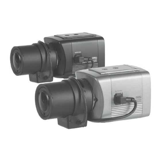
Summary of Contents for Genie HDC222
- Page 2 CAU T ION These servicing instructions are for use by qualified service personnel only. To reduce the risk of electric shock do not perform any servicing other than that contained in the operating instructions unless you are qualified to do so. Use CEPower Supply Only...
-
Page 3: Table Of Contents
CONTENTS 1. CAUTIONS 2. IMPORTANT SAFETY INSTRUCTIONS 3. FEATURES 4. EQUIPMENT AND ACCESSORIES 5. CAMERA COMPONENT DESCRIPTIONS 6. INSTALLATION 7. DIMENSIONS 8. SPECIFICATION 9. OSD MANUAL... -
Page 4: Cautions
1. CAUTIONS This device complies with Part 15 of the FCC Rules. Operation is subject to the following two conditions; 1. This device may not cause harmful interference. 2. This device must accept any interference received, including interference that may cause undesired operation. Note This equipment has been tested and found to comply with the limits for a Class A digital device, pursuant to part 15 of the FCC Rules. - Page 5 1. CAUTIONS Correct Disposal of This Product (Waste Electrical & Electronic Equipment) (Applicable in the European Union and other European countries with separate collection systems) This marking shown on the product or its literature, indicate that it should not be disposed with other household wastes at the end of its working life. To prevent possible harm to the environment or human health from uncontrolled waste disposal, please separate this from other types of wastes and recycle it responsibly to promote the sustainable reuse of material resources.
-
Page 6: Important Safety Instructions
2. IMPORTANT SAFETY INSTRUCTIONS 1) Read these instructions. 2) Keep these instructions. 3) Heed all warnings. 4) Follow all instructions. 5) Do not use this apparatus near water. 6) Clean only with a dry lint free cloth. 7) Do not block any ventilation openings. Install in accordance with the manufacturer’s instructions. -
Page 7: Features
3. FEATURES • High Resolution SONY 1/3” 2.1M/P Progressive Colour CMOS Image Sensor, 1920x1080 30fps • Supports Various Digital Video Outputs 720p60, 720p50, 1080p30, 1080p25 • Video Outputs Primary HD-SDI (BNC) Test/Setup TV Out (Test Point-adapter to BNC included), NTSC/PAL selectable •... -
Page 8: Equipment And Accessories
4. EQUIPMENT AND ACCESSORIES H D C CTV D ig it al V id eo C a me ra A uto I ri s Lens C onnec t i on P lu g C -Mount Adap te r Rin g O pe rat ion M an u a l NOTE PLEASE REMOVE PROTECTIVE FILM... -
Page 9: Camera Component Descriptions
5. CAMERA COMPONENT DESCRIPTIONS • FRONT TRIPOD MOUNTING HOLE (1/4"-20 UNC) C-MOUNT ADAPTER RING MOUNT COVER AUTO CS-MOUNT ADAPTER RING IRIS JACK CS-MOUNT ADAPTER RING FIXING SCREW (2EA) TRIPOD MOUNTING HOLE (1/4"-20 UNC) - Page 10 5. CAMERA COMPONENT DESCRIPTIONS • BACK ➊ ➋ ➎ ➐ ➊ ➋ ➎ ➐ VIDEO VIDEO HD SDI HD SDI OFF/ON OUTPUT OFF/ON OUTPUT MENU/SET MENU/SET ➍ ➍ ➑ ➑ POWER POWER ➌ ➌ ➏ ➏ VIDEO VIDEO ➒ ➒ ➓...
-
Page 11: Installation
6. INSTALLATION • LENS CONNECTION Mega Pixel Lenses are sold separately. Lenses such as an Auto Iris Lens, CS-Mount lens and C-Mount lens can be used (adapter included for C-Mount Lens). NOTE • Please keep the lens clean. • Any foreign objects and fingerprint marks on the lens can cause inferior image quality, especially in low light level conditions When Using an Auto Iris Lens 1. - Page 12 6. INSTALLATION 3. Remove the cover of the auto iris lens connection plug and solder the lens cable to the connector pins inside the plug. * PIN ASSIGNMENT OF THE LENS CONNECTOR 1) Video Auto Iris Lens Pin 1: Power source (DC 12V) Pin 3: Video signal Pin 4: Shield, GND (Ground) 2) DC Auto Iris Lens...
- Page 13 6. INSTALLATION 5. Insert the connection plug from the auto iris lens cable into the auto lens connector, which is located on the side of the camera. * NOTE Use the lens under the specification as shown. Otherwise the lens can damage the camera or abnormal fixing may result.
- Page 14 6. INSTALLATION Installation of C-Mount Lens C-MOUNT ADAPTER RING CS-MOUNT ADAPTER RING Installation of CS-Mount Lens CS-MOUNT ADAPTER RING...
-
Page 15: Monitor Connection
6. INSTALLATION • MONITOR CONNECTION RECEIVER DISPLAY - DC12V DEVICE VIDEO HD SDI INPUT HD SDI OFF/ON OUTPUT HD SDI OUTPUT MENU/SET POWER VIDEO MONITOR BNC FEMALE VIDEO OUTPUT DC12V VIDEO INPUT DC12V REGULATED POWER SUPPLY RECEIVER - DC12V/AC24V DISPLAY DEVICE VIDEO HD SDI INPUT... -
Page 16: Dimensions
7. DIMENSIONS Unit(mm) TRIPOD MOUNTING HOLE (1/4"-20 UNC, Depth 5) 75.5 (C-MOUNT) 70.5 (CS-MOUNT) TRIPOD MOUNTING HOLE (1/4"-20 UNC, Depth 5) -
Page 17: Specification
8. SPECIFICATION Image Device SONY 1/3” 2.1MP Progressive Colour CMOS Image Sensor Effective Pixels 1 9 8 4 (H) x 1 1 0 5 (V ) 3 0 f p s Unit Cell Size 2 . 8 u m (H) x 2 . 8 u m (V ) H D - S D I: 7 2 0 p 6 0 , 7 2 0 p 5 0 , 1 0 8 0 p 3 0 , 1 0 8 0 p 2 5 Video Output Mode T V O u t : NT SC / P AL S e le c t a b le... -
Page 18: Osd Manual
9. OSD MANUAL • Menu Structure SETUP EXPOSURE WHITE BALANCE WDR / BLC DAY & NIGHT IMAGE SPECIAL SYSTEN RESET DATA ALL Main Sub Menu Sub Menu BRIGHTNESS 0 ~ 20 AE MODE NORMAL AE / INDOOR LENS(IRIS) MANUAL / AUTO 1/30 (25), 1/60 (50), 1/120 (100), 1/240, 1/500, LEVEL MANUAL /... - Page 19 9. OSD MANUAL Main Sub Menu Sub Menu SHARPNESS 0 ~ 20 GAMMA 0 ~ 4 FLIP OFF, H FLIP, V FLIP, HV FLIP IMAGE LENS SHADING OFF, ON DZOOM 1x, 2x, 4x, 6x, 8x, 10x, 12x, 14x, 16x, 18x, 20x RESET DATA BACK / DEF.
-
Page 20: Function Description
9. OSD MANUAL • Function Description 0. SETUP - EXPOSURE : Go sub menu for camera exposure control. - WHITE ALANCE : Go sub menu for camera white balance control. - WDR/BLC : Go sub menu for camera WDR or BLC action. - DNR : Control noise reduction setting. - Page 21 9. OSD MANUAL : WDR weight control level setting in WDR mode. - WDR WGT : Display BLC control zone on screen. - BLC OSD - BLC POS-X : Select BLC control zone vertical position. - BLC POS-Y : Select BLC control zone horizontal position. - BLC SIZ-X : Select BLC control zone vertical size.
- Page 22 9. OSD MANUAL - HLMASK : Mask image highlight area. • LEVEL : Select highlight level. • COLOR : Select mask colour. - PATTERN : Colour bar display select. 8. SYSTEM - SDI FORMAT : 1080P / 720P - SDI FPS : 30 or 25 fps in 1080p mode.