Table of Contents
Advertisement
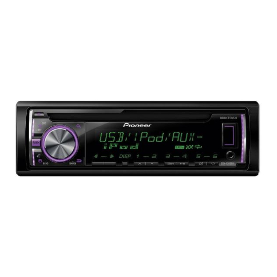
CD RDS RECEIVER
DEH-X36UI
DEH-X3600UI
DEH-X3650UI
DEH-X3650UI
DEH-X3650UI
DEH-X3690UI
This service manual should be used together with the following manual(s):
Model No.
Order No.
CRT4759
CX-3287
PIONEER CORPORATION
PIONEER ELECTRONICS (USA) INC. P.O. Box 1760, Long Beach, CA 90801-1760, U.S.A.
PIONEER EUROPE NV Haven 1087, Keetberglaan 1, 9120 Melsele, Belgium
PIONEER ELECTRONICS ASIACENTRE PTE. LTD. 253 Alexandra Road, #04-01, Singapore 159936
PIONEER CORPORATION 2013
Mech. Module
S11.6STD
CD Mech. Module : Circuit Descriptions, Mech. Descriptions, Disassembly
1-1, Shin-ogura, Saiwai-ku, Kawasaki-shi, Kanagawa 212-0031, Japan
DEH-X36UI/XNUC
/XNUC
/XNCS
/XNGS
/XNGS1
/XNID
Remarks
ORDER NO.
CRT5370
/XNUC
K-ZZZ JULY 2013 Printed in Japan
Advertisement
Table of Contents

Related Manuals for Pioneer DEH-X36UI/XNUC


Summary of Contents for Pioneer DEH-X36UI/XNUC
- Page 1 PIONEER CORPORATION 1-1, Shin-ogura, Saiwai-ku, Kawasaki-shi, Kanagawa 212-0031, Japan PIONEER ELECTRONICS (USA) INC. P.O. Box 1760, Long Beach, CA 90801-1760, U.S.A. PIONEER EUROPE NV Haven 1087, Keetberglaan 1, 9120 Melsele, Belgium PIONEER ELECTRONICS ASIACENTRE PTE. LTD. 253 Alexandra Road, #04-01, Singapore 159936...
-
Page 2: Safety Information
Transistors Q101 in PCB drive the laser diodes. When Q101 is shorted between their terminals, the laser diodes will radiate beam. If the top cover is removed with no disc loaded while such short-circuit is continued, the naked eyes may be exposed to the laser beam. DEH-X36UI/XNUC... - Page 3 CAUTION Danger of explosion if battery is incorrectly replaced. Replaced only with the same or equivalent type recommended by the manufacturer. Discord used batteries according to the manufacturer's instructions. DEH-X36UI/XNUC...
-
Page 4: Table Of Contents
10.3 CD CORE UNIT (S11.6VA) ........................48 10.4 WAVEFORMS ............................50 11. PCB CONNECTION DIAGRAM........................52 11.1 TUNER AMP UNIT..........................52 11.2 KEYBOARD UNIT ..........................56 11.3 CD CORE UNIT (S11.6VA) ........................58 12. ELECTRICAL PARTS LIST .......................... 60 DEH-X36UI/XNUC... -
Page 5: Service Precautions
Compared with eutectic solders, lead-free solders have higher bond strengths but slower wetting times and higher melting temperatures (hard to melt/easy to harden). The following lead-free solders are available as service parts: Parts numbers of lead-free solder: GYP1006 1.0 in dia. GYP1007 0.6 in dia. GYP1008 0.3 in dia. DEH-X36UI/XNUC... -
Page 6: Specifications
2. SPECIFICATIONS 2.1 SPECIFICATIONS DEH-X36UI/XNUC, DEH-X3600UI/XNUC General Signal-to-noise ratio ..94 dB (1 kHz) (IHF-A network) Power source ....14.4 V DC (10.8 V to 15.1 V al- Number of channels ..2 (stereo) lowable) MP3 decoding format ..MPEG-1 & 2 Audio Layer 3 Grounding system ....Negative type... - Page 7 Specifications and the design are subject to Gain ........ +6 dB to –24 dB modifications without notice. Phase ......Normal/Reverse CD player System ......Compact disc audio system Usable discs ....Compact disc Signal-to-noise ratio ..94 dB (1 kHz) (IEC-A network) DEH-X36UI/XNUC...
- Page 8 Usable sensitivity ..... 28 µV (S/N: 20 dB) WMA decoding format ..Ver. 7, 7.1, 8, 9, 10, 11, 12 (2 ch Signal-to-noise ratio ..62 dB (IEC-A network) audio) Note (Windows Media Player) Specifications and the design are subject to modifications without notice. DEH-X36UI/XNUC...
-
Page 9: Disc/Content Format
WMA decoding format ..Ver. 7, 7.1, 8, 9, 10, 11, 12 (2 ch Signal-to-noise ratio ..62 dB (IEC-A network) audio) Note (Windows Media Player) Specifications and the design are subject to modifications without notice. 2.2 DISC/CONTENT FORMAT DEH-X36UI/XNUC... -
Page 10: Basic Items For Service
Distortion Noise Volume too low Volume too high Volume fluctuating Sound interrupted 3.2 PCB LOCATIONS CD Core Unit (S11.6VA) Tuner Amp Unit A:DEH-X36UI/XNUC B:DEH-X3600UI/XNUC C:DEH-X3650UI/XNCS E:DEH-X3650UI/XNGS F:DEH-X3650UI/XNGS1 Keyboard Unit G:DEH-X3690UI/XNID Unit Number : QWM3628(A,B) Unit Number : QWM3629(C) Unit Number : QWM3630(E,F) -
Page 11: Jigs List
CD Mechanism Module 3.4 CLEANING Before shipping out the product, be sure to clean the following portions by using the prescribed cleaning tools: Portions to be cleaned Cleaning tools CD pickup lenses Cleaning liquid : GEM1004 Cleaning paper : GED-008 DEH-X36UI/XNUC... -
Page 12: Block Diagram
Q751 FCO+ B.UP FCO- Q752 SPO+ SPINDLE MOTOR CLCONT SPO- VDCONT LDIN LOEJ LCOP MUTE LOADING/CARRIAGE SLLDO+ CONT LCOM MOTOR SLLDO- RESET RESET RESET CDRST DSCSNS HOME CD DATA (CDSRQ,CDSTBY,SKIP, CD DATA (CDSRQ,CDSTBY,SKIP, SCL,SDA,DATA,BCLK,LRCK,WAIT) SCL,SDA,DATA,BCLK,LRCK,WAIT) S903 S901 DSCSNS HOME DEH-X36UI/XNUC... - Page 13 ELECTRONIC VOLUME/ SOURCE SELECTOR IC201 :DEH-X36UI/XNUC PM9013A :DEH-X3600UI/XNUC JA251 TUNL :DEH-X3650UI/XNCS INAN1L OUTPL RCAG :DEH-X3650UI/XNGS :DEH-X3650UI/XNGS1 RCAG Q252 Q251 :DEH-X3690UI/XNID 3.3V JA901 MCLK EVOL_MCK FUSE 10A LRCLK EVOL_LRCK B.UP EVOL_BCK BCLK 15 B.UP 12(11) EVOL_DATA OUTFL FLIn DATA EVOL_DT 13(12)
-
Page 14: Diagnosis
In case of the above signal, the communication Source keys with Grille microcomputer may fail. operative If the time interval is not 300 msec, the oscillator may be defective. Source ON SYSPW <- H Pin 8 Completes power-on operation. (After that, proceed to each source operation) DEH-X36UI/XNUC... -
Page 15: Error Code List
: Servo-related errors CD Off, Eject, ACC Off, Back-up Off, Communication reset, Reset Load NG/Eject NG(50) : Reload, Eject, ACC Off, Back-up Off, Communication reset, Reset Failure in retried turning for ejection : CD On, Eject, ACC Off, Back-up Off, Communication reset, Reset DEH-X36UI/XNUC... - Page 16 Transfer the audio files to the USB storage device fails to disappear even after the engine is and connect. switched off/on, contact your dealer or an authorized Pioneer Service Station for The connected USB storage device has security en- assistance. abled.
- Page 17 Run the same command for another track. Apps TRY AGAIN START UP APP Unable to save thumb rating. Unable to save BookMark. The application has not started running yet. Unable to add station. Follow the instructions that appear on the Try again later. screen. DEH-X36UI/XNUC...
-
Page 18: Connector Function Description
16 14 12 10 8 6 4 2 REAR OUTPUT or SUBWOOFER OUTPUT 1 FL+ 9 NC 10 NC 2 FR+ 11 NC 3 FL- 4 FR- 12 NC 5 RL+ 13 ACC 6 RR+ 14 B.REM 15 B.UP 7 RL- 16 GND 8 RR- DEH-X36UI/XNUC... -
Page 19: Service Mode
SOURCE No light Draw2 No light Conf. LCD pattern 1 BAND Draw 3 (* And change ILM color) Conf. LCD pattern 2 ROTARY center Draw 4 Green Drawings Style Draw1 ALL light up Draw2 ALL light off Draw3 Draw4 DEH-X36UI/XNUC... -
Page 20: Display Test Mode 2
The screen gets still when entering this item. On (an initial value or On (state when setting value of default entering test mode) Switching to next display menu) by pressing “ 1 ” + “ 3 ” buttons together. DEH-X36UI/XNUC... -
Page 21: Software Version Up Method
The display is continued until the power supply is turned OFF. If the power supply is turned ON again, the display is not changed. The upgrading using USB is disabled, so it is necessary to write programs in serial Flash using E10A. DEH-X36UI/XNUC... -
Page 22: Cd Test Mode
When the power is turned on/off the gain of the RFAMP is reset to 0 dB. At the same time all the self-adjusting values shall return to the default setting. Do not do Tracking Servo Close before doing Focus Servo Close. (Because the overcurrent flows) DEH-X36UI/XNUC... -
Page 23: Disassembly
Slide the Tuner Amp Assy in the direction of the arrow. Lift off the Tuner Amp Assy from the Heat Sink side. The Tuner Amp Assy is fixed into the ditch. Disconnect the FFC and then remove the CD Mechanism Module. CD Mechanism Module Fig.2 DEH-X36UI/XNUC... - Page 24 Tuner Amp Unit Remove the two screws. Remove the two screws and then remove the Tuner Amp Unit. Fig.3 - Attention of removing (Fig.4) Don’t remove this screws excluding the dismantlement of the CD Mechanism Module. CD Mechanism Module Fig.4 DEH-X36UI/XNUC...
- Page 25 1. Attach the button from the front side of the panel. Fig.7 2. Attach the spring to the arm as shown in the figure. The bended tip of the spring is set to this side. Hitch the spring to the groove. Fig.8 DEH-X36UI/XNUC...
- Page 26 4. Fit the boss on the lower side of the arm in the lower hole of the panel, and then warp the rib on the panel in the direction shown in the figure and fit the boss of the arm in the panel. Fig.9 DEH-X36UI/XNUC...
- Page 27 2. Be careful not to hold the solid line portions or the CRG mecha part or insert foreign substances, to prevent distortion. 3. When holding the sides of the upper chassis, do not apply excessive force to prevent distortion. (Approx. 8N or less) Handling OK Handling NG DEH-X36UI/XNUC...
- Page 28 Fig 3 Fig 4 [Incorrect built-in state] The chassis is not nipped between Outer holder Normal built-in state the PU case and the PU rack. Rear end of feeding screw DEH-X36UI/XNUC...
-
Page 29: Each Setting And Adjustment
1k ohms in series. The load and eject operation is not guarantied with the mechanism upside down. If the mechanism is blocked due to mistaken eject operation, reset the product or turn off and on the ACC to restore it. DEH-X36UI/XNUC... -
Page 30: Checking The Grating After Changing The Pickup Unit
Because of eccentricity in the disc and a slight misalignment of the clamping center the grating waveform may be seen to "wobble" ( the phase difference changes as the disc rotates). The angle specified above indicates the average angle. Hint Reloading the disc changes the clamp position and may decrease the "wobble". DEH-X36UI/XNUC... - Page 31 Grating waveform Ech -> Xch 20 mV/div, AC Fch -> Ych 20 mV/div, AC 0 degrees 30 degrees 45 degrees 60 degrees 75 degrees 90 degrees DEH-X36UI/XNUC...
-
Page 32: Pcl Output Confirmation
The frequency of the clock signal is 600 kHz that is divided by 20th of the oscillation frequency of X601 (12MHz). The clock signal should be 600 kHz(- 25 Hz, + 25 Hz). If the clock signal is out of the range, the X'tal (X601) should be replaced with new one. DEH-X36UI/XNUC... -
Page 33: Exploded Views And Parts List
Therefore, when replacing, be sure to use parts of identical designation. Screw adjacent to mark on the product are used for disassembly. For the applying amount of lubricants or glue, follow the instructions in this manual. (In the case of no amount instructions,apply as you think it appropriate.) DEH-X36UI/XNUC... -
Page 34: Packing
9.1 PACKING X3600UI/XNUC X3650UI/XNCS X3650UI/XNGS X3650UI/XNGS1 X3690UI/XNID X36UI/XNUC X3600UI/XNUC X3600UI/XNUC X3650UI/XNCS X3650UI/XNCS X3650UI/XNGS X3650UI/XNGS X3650UI/XNGS1 X3650UI/XNGS1 X3690UI/XNID X3690UI/XNID X3650UI/XNCS X3650UI/XNGS X36UI/XNUC X3650UI/XNGS1 X3600UI/XNUC X3690UI/XNID X36UI/XNUC X3600UI/XNUC X3600UI/XNUC X3650UI/XNCS X3650UI/XNGS X3650UI/XNGS1 X3690UI/XNID DEH-X36UI/XNUC... - Page 35 See Contrast table (2) Screw See Contrast table (2) 15-3 Service Network See Contrast table (2) Handle QNC3021 (2) CONTRAST TABLE DEH-X36UI/XNUC, DEH-X3600UI/XNUC, DEH-X3650UI/XNCS, DEH-X3650UI/XNGS, DEH-X3650UI/XNGS1 and DEH-X3690UI/XNID are constructed the same except for the following: DEH-X36UI/ DEH-X3600UI/ DEH-X3650UI/ DEH-X3650UI/ DEH-X3650UI/ Mark...
-
Page 36: Exterior
9.2 EXTERIOR DEH-X36UI/XNUC... - Page 37 YEK5001 Cover CNS7068 Detachable Grille Assy See Contrast table (2) Cushion QNM3097 Screw BPZ20P100FTC (2) CONTRAST TABLE DEH-X36UI/XNUC, DEH-X3600UI/XNUC, DEH-X3650UI/XNCS, DEH-X3650UI/XNGS, DEH-X3650UI/XNGS1 and DEH-X3690UI/XNID are constructed the same except for the following: DEH-X36UI/ DEH-X3600UI/ DEH-X3650UI/ DEH-X3650UI/ DEH-X3650UI/ Mark Description XNUC...
-
Page 38: Cd Mechanism Module
9.3 CD MECHANISM MODULE (A) : GEM1024 (B) : GEM1043 DEH-X36UI/XNUC... - Page 39 Rack CNV8342 Guide CNW2240 Roller CNW1172 ..CNW2241 Roller CNW1175 ..CNW1177 CNW1178 Gear CNW1180 Gear CNW1181 ..Gear CNW1183 Rack CNW1184 Gear CNW1185 Gear CNW1186 Gear CNW1187 Gear CNW2287 Clamper CNW1190 CNW1192 Holder CNW1193 Holder CNW1194 Damper CNW1197 DEH-X36UI/XNUC...
-
Page 40: Schematic Diagram
R807 AUXR No differentiation is made between chip resistors and AUXGND discrete resistors. RGBST/ILMCLR2 Symbol indicates a capacitor. No differentiation is made between chip capacitors and RGBCK/ILMCLR1 DEH-X36UI/XNUC US5V discrete capacitors. USB5V DEH-X3600UI/XNUC CN1931 DPDT USBGND DEH-X3650UI/XNCS The > mark found on some component parts indicates... - Page 41 CTF1713- 2.2k D302 R812 2.2k RGBCK/ILMCLR1 RGBDT/DIMMER R813 2.2k B.REM&A.ANT C330 Dim off 12.13 V R814 2.2k Q875 KYDT Dim on 8.03 V DPDT LTC043EEB R816 2.2k ROT0 ILMPW R817 2.2k ROT1 SWVDD L851 IC801 DPDT OUTY TC7SET08FUS1 SWVDD DEH-X36UI/XNUC...
- Page 42 The pin number of left side is a number on the PCB (silk printing). The pin number of right side (in the IC frame) means the pin number of IC itself. DEH-X36UI/XNUC...
- Page 43 POWER SUPPLY mber of IC itself. DEH-X36UI/XNUC...
- Page 44 DEH-X36UI/XNUC...
- Page 45 DEH-X36UI/XNUC...
-
Page 46: Keyboard Unit
SEG37 COM1 SOURCE COM1 SEG38 COM0 COM0 SEG39 CSG1155- DGND SEG40 SOURCE SEG41 SEG42 SEG43 SEG69 IC1941 PNJ4833M C1855 1u/10 REMOTE C1854 0.01u/16 R1942 R1944 DGND R1941 DGND RED Key GREEN Key BLUE Key V1802 SEGMENT LCD CAW2041- ILMGND DEH-X36UI/XNUC... - Page 47 1u/10 2.2k USB5V CN801 C1854 RGBCK 0.01u/16 RGBST DGND AUXGND AUX:+2.0 dBs AUXR SOURCE DGND AUXL DSENS BLUE LCD DGND GREEN LCD CN1911 RED LCD CKS6443- C1912 0.1u/16 ILMGND DGND C1914 ILMGND DGND C1915 ILMGND DGND JA1921 YKN5006-A ILMGND DEH-X36UI/XNUC...
-
Page 48: Cd Core Unit (S11.6Va)
FCO+ C308 CSN1081-A R309 1u/10 PRTLIM TKRNF (1608) DSCSNS PRTF MOTOR DRIVER LOGIC TABLE FCRNF PRTT LOAD PLAY TKCDET PREVCC CLCONT FCCDET LOEJ SWITCHES: CONT CD CORE UNIT(S11.6VA) S901:HOME SWITCH..ON-OFF S903:DSCSNS SWITCH..ON-OFF PGND The underlined indicates the switch position. DEH-X36UI/XNUC... - Page 49 5 SCL SKIP 6 SKIP R701 7 SDA RESET 8 RESET CN701 9 VDD 3.3V 10 GND DATA 11 DATA BCLK 12 BCLK LRCK 13 LRCK 14 GND 15 PGND VER LOGIC TABLE /WAIT 16 WAIT PLAY IIC-BUS Digital PGND DEH-X36UI/XNUC...
-
Page 50: Waveforms
1 V/div fRFAGC 500 mV/div 500 mV/div 500 mV/div 9TIN 500 mV/div Focus Search waveform Track Open waveform 100 Track Jump waveform (32 Track Jump x 3) Ref.: Ref.: Ref.: REFO REFO REFO Mode: Mode: Mode: TEST TEST TEST DEH-X36UI/XNUC... - Page 51 12 cm CD Eject operation 12 cm CD Eject operation Ref.: Ref.: Mode: Mode: Normal Normal 500 μs/div fRFAGC 1 V/div 9TIN 1 V/div 1 V/div aFIN 1 V/div μ Black Dot (800 m) during play Ref.: REFO Mode: Normal DEH-X36UI/XNUC...
-
Page 52: Pcb Connection Diagram
C318 SIDE B C251 C259 R252 Chip Part P.C.Board D551 C562 R555 C551 C556 C557 C563 C558 IC551 C555 C564 C553 R553 R552 R554 C570 C565 C552 D552 L551 > P 251 (A,6,130) Fuse 3.0 A CEK1386 CN701 CN1931 DEH-X36UI/XNUC... - Page 53 CN701 R703 R877 C872 C852 IC552 R878 C561 C873 C802 C851 C560 R801 L851 C811 C559 R808 R851 C808 R804 C814 R803 C809 C803 IC801 D802 R813 C813 D811 D803 L801 VA802 C810 R818 C804 C806 CN801 C801 FRONT DEH-X36UI/XNUC...
- Page 54 TUNER AMP UNIT TESTIN DEH-X36UI/XNUC...
- Page 55 SIDE B DEH-X36UI/XNUC...
-
Page 56: Keyboard Unit
SIDE A KEYBOARD UNIT SIDE B C1941 R1943 D1923 C1923 C1865 C1913 C1867 C1914 C1866 R1922 R1872 R1873 CN1931 CN801 C1803 C1801 C1802 D1801 R1810 C1852 R1851 R1852 C1868 C1869 C1870 C1861 C1915 C1860 C1859 R1857 R1856 C1858 C1857 C1856 DEH-X36UI/XNUC... - Page 57 DEH-X36UI/XNUC...
-
Page 58: Cd Core Unit (S11.6Va)
TH201 R254 C235 CN101 LOAD/CRG R246 MOTOR R232 HOME S901 C201 CN702 R253 R245 C238 C710 C299 R706 R297 C205 C705 C707 C220 R702 R701 SPDL MOTOR CN701 CN701 C702 C307 REFO1 R710 C701 C308 C312 IC301 C306 R309 DEH-X36UI/XNUC... - Page 59 C210 C223 C211 R110 R111 R240 R282 C204 C284 R281 C222 IC201 C281 C218 C301 C282 R216 R218 R291 C219 R229 C217 C283 C216 C228 C221 R217 C215 C212 R260 C250 C708 S905 R313 R312 DSCSNS R311 S903 R310 DEH-X36UI/XNUC...
-
Page 60: Electrical Parts List
The expression of the unit in this manual is shown by u instead of . Please do not make a mistake. Circuit Symbol and No. Part No. Circuit Symbol and No. Part No. IC 552 (A,106,24) IC BD2232G-G A:DEH-X36UI/XNUC IC 601 (A,111,77) IC R5S726A0D216FP B:DEH-X3600UI/XNUC IC 671 (A,131,75) IC S-80827CNMC-B8M... - Page 61 (A,139,104) (E,F,G) RS1/16SS331J R 647 (A,98,78) RS1/16SS101J R 404 (A,142,99) RS1/16SS105J R 648 (A,95,76) RS1/16SS102J R 406 (A,154,108) RS1/16SS105J R 649 (A,95,75) RS1/16SS102J R 650 (A,95,74) RS1/16SS102J R 407 (A,139,96) RS1/16SS330J R 651 (A,97,71) RS1/16SS473J R 408 (A,137,97) (A,B,C) RS1/16SS471J DEH-X36UI/XNUC...
- Page 62 C 401 (A,154,100) CKSSYB104K10 R 912 (A,141,41) RS1/10SR1R0J C 402 (A,155,101) CKSSYB103K16 R 913 (A,154,41) RS1/16SS223J C 403 (A,153,102) CKSRYB105K10 R 914 (A,131,40) RS1/16SS223J C 405 (A,162,101) CKSSYB103K16 R 941 (A,94,121) RS1/16SS223J C 406 (A,160,101) CKSSYB103K16 R 942 (A,94,122) RS1/16SS473J DEH-X36UI/XNUC...
- Page 63 (A,135,42) 4.7 uF CCG1201 C 555 (A,25,112) CKSSYB682K25 C 923 (A,159,41) 4.7 uF CCG1201 C 556 (A,32,120) CEVQW221M6R3 C 926 (A,140,44) 4.7 uF CCG1201 C 557 (A,33,116) CKSRYB105K10 C 927 (A,140,42) CKSSYB102K50 C 560 (A,108,21) CKSRYB105K10 C 941 (A,96,124) CKSRYB104K16 DEH-X36UI/XNUC...
- Page 64 R 218 (B,10,36) RS1/16SS472J R 1851 (B,50,16) RS1/10SR222J R 1852 (B,48,16) RS1/10SR222J R 229 (B,13,35) RS1/16SS471J R 232 (A,31,55) RS1/16SS0R0J R 1853 (B,52,9) RS1/10SR222J R 237 (B,34,45) RS1/16SS221J R 1854 (B,41,18) RAB4CQ102J R 240 (B,35,40) RS1/16SS473J R 1855 (B,42,22) RAB4CQ102J DEH-X36UI/XNUC...
- Page 65 C 236 (B,8,41) CKSSYB104K10 C 238 (A,26,45) CKSRYB104K16 C 299 (A,26,43) CKSSYB104K10 C 302 (B,29,12) CKSSYB102K50 C 303 (B,30,12) CKSSYB102K50 C 304 (B,28,12) CKSSYB223K16 C 305 (B,27,12) CKSSYB104K10 C 306 (A,32,7) CKSSYB104K10 C 307 (A,42,19) CKSRYB105K10 C 308 (A,32,16) CKSRYB105K10 DEH-X36UI/XNUC...