Table of Contents
Advertisement
Advertisement
Table of Contents
Troubleshooting

Related Manuals for Central Pneumatic 61489


Summary of Contents for Central Pneumatic 61489
-
Page 2: Table Of Contents
IMPORTANT STOP STOP DO NOT RETURN TO STORE This unit was fully tested and inspected prior to shipment and will operate properly when instructions are followed. Refer to your owner’s manual for basic troubleshooting. To avoid unnecessary return to the store, simply call Compressor Support toll free for additional assistance. 1-888-866-5797 Compressor Support: Please have your model number and serial number available. -
Page 3: General Safety Rules
GENERAL SAFETY RULES Additional safety protection will be required in some environments. For example, the working area WARNING: may include exposure to a noise level which can lead to Read and understand all instructions. Failure to hearing damage. The employer and user must ensure follow all instructions listed below may result in electric that any necessary hearing protection is provided shock, fire, and/or serious personal injury. - Page 4 GENERAL SAFETY RULES Never point any tool toward yourself or others. Disconnect the power supply, open the drain valve to decompress the tank and allow water to drain, Keep the exterior of the air compressor dry, clean, and allow the air compressor to become cool to the and free from oil and grease.
-
Page 5: Specific Safety Rules
SPECIFIC SAFETY RULES Know your power tool. Read operator’s manual Always follow all safety rules recommended by the carefully. Learn its applications and limitations, as well manufacturer of your tool, in addition to all safety as the specific potential hazards related to this tool. rules for the air compressor. -
Page 6: Symbols
Do not adjust regulator to result in output pressure greater than marked maximum pressure of attachment. Do not use at pressure greater than the rated maximum pressure of this compressor. -
Page 8: Electrical
SPEED AND WIRING The no-load speed of the electric motor varies by model and specification. The motor speed is not constant and decreases under a load or with lower voltage. For voltage, the wiring in a shop is as important as the motor’s horsepower rating. A line intended only for lights cannot properly carry a power tool motor. -
Page 9: Glossary Of Terms
TOOLS NEEDED The following tools are needed in order to assemble the wheel kit. TWO ADJUSTABLE WRENCHES... -
Page 10: Features
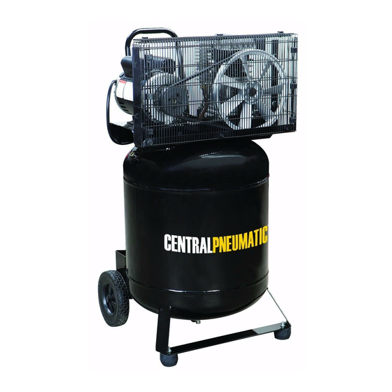
FEATURES PRODUCT SPECIFICATIONS Running Horsepower ........... 2 HP Lubrication ...............Oil Air Tank Capacity ............29 gal. Gauges ............2.0 in. diameter Air Pressure ............150 PSI max. Input........120 V, 60 Hz, AC only, 15 Amps Air Delivery ......... 7.5 SCFM @ 40 PSI Net Weight ............169.8 lbs. -
Page 11: Assembly
FEATURES KNOW YOUR AIR COMPRESSOR PRESSURE REGULATOR KNOB See Figure 2. Use the pressure regulator knob to adjust the amount of Before attempting to use this product, familiarize yourself air being delivered through the hose. with all operating features and safety rules. REGULATOR PRESSURE GAUGE DESCRIPTION The current line pressure is displayed on the regulator... - Page 12 ASSEMBLY ASSEMBLING THE RUBBER FOOT AND WHEELS WASHER See Figure 3. WASHER(s) Mount the rubber feet as shown in figure. Tighten firmly with an open-end wrench (not included) to secure it in position. RUBBER FOOT Mount the wheels as shown in figure. WASHER Tighten firmly with an open-end wrench (not included) SCREW...
- Page 13 ASSEMBLY PRESSURE PRESSURE BREAKING IN THE PUMP REGULATOR SWITCH See Figures 4 - 7. KNOB (ON/OFF) Check and tighten all bolts, fittings, etc. Turn the pressure regulator knob fully clockwise to open the air flow. Place the lever of the pressure switch in ‘OFF’ position and plug in the power cord.
-
Page 14: Operation
OPERATION WARNING: WARNING: Do not allow familiarity with tools to make you careless. Your tool may require more air consumption than this Remember that a careless fraction of a second is air compressor is capable of providing. Check the tool sufficient to inflict serious injury. -
Page 15: Operation
OPERATION DRAINING THE TANK See Figures 8 - 9. To help prevent tank corrosion and keep moisture out of the air used, the tank of the compressor should be drained daily. A correct use of the drain valve: Verify that the compressor is turned off. Holding the handle, tilt the compressor toward the drain valve so that it’s set in a lower position. -
Page 16: Maintenance
MAINTENANCE CHECK THE OIL LEVEL AT REGULAR INTERVALS WARNING: See Figure 11. Place the compressor on a level and straight surface. The When servicing, use only identical Harbor Freight Tools replacement parts. Use of any other parts may create a oil level must be between the two marks MAX and MIN on hazard or cause product damage. - Page 17 MAINTENANCE When the oil has drained out, re-fit the oil drain plug (fig. 11). Fill new oil through the oil filler opening until it comes up to the required level. Do not overfill. After topping up, tighten the oil fill plug (fig. 12), making sure that there are no leaks during use.
-
Page 18: Maintenance
MAINTENANCE CLEANING THE INTAKE FILTER AIR FILTER See Figure 17. The intake filter prevents dust and dirt being drawn in. It is essential to clean this filter after at least every 100 hours in service. A clogged intake filter will decrease the compressor’s performance dramatically. -
Page 19: Troubleshooting
TROUBLESHOOTING Problem Possible Cause Solution Compressor will not run Loss of power or overheating Check for proper use of extension cord No electrical power Check to be sure unit is plugged in Check fuse/breaker or motor over- load Blown shop/house fuse Replace shop/house blown fuse Shop/house breaker open Reset shop/house breaker, determin-... -
Page 20: Troubleshooting
TROUBLESHOOTING Problem Possible Cause Solution Air leak from the valve of the pressure Check valve does not perform its Unscrew the hex-shaped head of the switch function correctly due to wear or dirt on check valve, clean the housing and the the seal special rubber disk (replace if worn). - Page 21 NOTES...
-
Page 22: Warranty
Limited 90 Day Warranty Harbor Freight Tools Co. makes every effort to assure that its products meet high quality and durability standards, and warrants to the original purchaser that this product is free from defects in materials and workmanship for the period of 90 days from the date of purchase. This warranty does not apply to damage due directly or indirectly, to misuse, abuse, negligence or accidents, repairs or alterations outside our facilities, criminal activity, improper installation, normal wear and tear, or to lack of maintenance. - Page 23 SIX GALLON OILLESS Portable Air Compressor Model No. 61489 Replacement Parts List Record Serial Number Here: Note: If product has no serial number, record month and year of purchase instead. Note: Some parts are listed and shown for illustration purposes only, and are not available individually as replacement parts.
- Page 25 PORTABLE AIR COMPRESSOR PARTS LIST− MODEL NO. 61489 The model number will be found on a plate attached to air tank. Always mention the model number in all correspondence regarding your PORTABLE AIR COMPRESSOR or when ordering replacement parts. KEY NO.
- Page 26 KEY NO. CODE DESCRIPTION Q.TY KEY NO. CODE DESCRIPTION Q.TY 2860101 CRANKCASE........1 9022001 OIL LEVEL ......... 1 2830001 CYLINDER ........1 9024029 BREATHER ........1 3860400 HEAD ..........1 9163010 GASKET ..........1 2860200 CRANKSHAFT ........1 9110014 SCREW..........1 2660500 CRANKCASE BOTTOM ....1 9004008 WASHER ...........