Table of Contents
Advertisement
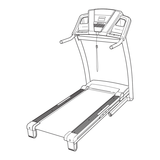
www.proform.com
Model No. PFTL96008.0
Serial No.
Write the serial number in the
space above for reference.
Serial Number
Decal
QUESTIONS?
If you have questions, or if parts
are missing, DO NOT CONTACT
THE STORE; please contact
Customer Care.
IMPORTANT: You must note the
product model number and
serial number (see the drawing
above) before contacting us:
1-888-533-1333
CALL TOLL-FREE:
Mon.–Fri. 6 a.m.–6 p.m. MT
Sat. 8 a.m.–4 p.m. MT
ON THE WEB:
www.proformservice.com
CAUTION
Read all precautions and instruc-
tions in this manual before using
this equipment. Save this manual
for future reference.
USER'S MANUAL
Advertisement
Table of Contents

Related Manuals for ProForm 680 LT


Summary of Contents for ProForm 680 LT
- Page 1 USER'S MANUAL Model No. PFTL96008.0 Serial No. Write the serial number in the space above for reference. Serial Number Decal QUESTIONS? If you have questions, or if parts are missing, DO NOT CONTACT THE STORE; please contact Customer Care.
-
Page 2: Table Of Contents
Apply the decal in the location shown. Note: The decals may not be shown at actual size. PROFORM is a registered trademark of ICON IP, Inc. -
Page 3: Important Precautions
13. To purchase a surge suppressor, see informed of all warnings and precautions. your local PROFORM dealer or call the tele- phone number on the front cover of this man- 3. Use the treadmill only as described. - Page 4 20. Never leave the treadmill unattended while it 24. Inspect and properly tighten all parts of the is running. Always remove the key, unplug treadmill regularly. DANGER: the power cord, and switch the reset/off cir- cuit breaker to the off position when the Always unplug the power treadmill is not in use.
-
Page 5: Before You Begin
Thank you for selecting the revolutionary PROFORM ual. To help us assist you, note the product model ® 680 LT treadmill. The 680 LT treadmill offers an im- number and serial number before contacting us. The pressive selection of features designed to make your model number and the location of the serial number workouts at home more enjoyable and effective. -
Page 6: Assembly
ASSEMBLY To hire an authorized service technician to assemble the treadmill, call 1-800-445-2480. Assembly requires two persons. Set the treadmill in a cleared area and remove all packing materials. Do not dispose of the packing materials until assembly is completed. Note: The underside of the treadmill walking belt is coated with high-performance lubricant. - Page 7 1. Make sure that the power cord is unplugged. With the help of a second person, carefully tip the treadmill onto its left side. Partially fold the Frame (53) so that the treadmill is more stable; do not fully fold the Frame yet. Remove and discard the two indicated bolts (A) and the shipping bracket (B).
- Page 8 3. Identify the Right Upright (79) and the Right Upright Spacer (83), which are marked with stickers. Insert the Upright Wire (86) through the Right Upright Spacer as shown. Then, set the Right Upright Spacer on the Base (60). Wire Tie Have a second person hold the Right Upright (79) near the Base (60).
- Page 9 5. With the help of a second person, carefully tip the treadmill onto its right side. Partially fold the Frame (53) so the treadmill is more stable; do not fully fold the Frame yet. Remove and discard the two indicated bolts (A) and the shipping bracket (B).
- Page 10 8. Remove the two ties from the bracket on the Left Handrail (101). Set the Left Handrail (101) on the Left Upright (77). Attach the Left Handrail with three 5/16" x 3/4" Bolts (4) and three 5/16" Star Washers (9); Ties do not fully tighten the Bolts yet.
- Page 11 10. Have a second person hold the console assem- bly near the Right Upright (79). Connect the Console Upright Wire (86) to the console wire. See the Assembly inset drawing. The connectors should slide together easily and snap into place. If they do not, turn one connector and try again.
- Page 12 12. If necessary, press the Left Accessory Tray (94) and the Right Accessory Tray (99) into the con- sole assembly. Console Assembly 13. Raise the Frame (53) to the position shown. Have a second person hold the Frame until this step is completed. Orient the Storage Latch (50) so that the large barrel and the Latch Knob (51) are in the posi- tions shown.
-
Page 13: Operation And Adjustment
Grounded Outlet Box the right). To purchase a surge suppressor, see Adapter your local PROFORM dealer or call the telephone Surge Suppressor number on the front cover of this manual and order part number 146148, or see your local electronics store. - Page 14 CONSOLE DIAGRAM Clip FEATURES OF THE CONSOLE designed to help you achieve specific fitness goals. For example, lose unwanted pounds with the 8-week The treadmill console offers a selection of features Weight Loss workout, or train for a long-distance run designed to make your workouts more effective.
-
Page 15: To Turn On The Power
HOW TO TURN ON THE POWER HOW TO USE THE MANUAL MODE IMPORTANT: If the treadmill has been exposed to 1. Insert the key into the console. cold temperatures, allow it to warm to room tem- perature before turning on the power. If you do not See HOW TO TURN ON THE POWER at the left. - Page 16 4. Change the incline of the treadmill as desired. 6. Measure your heart rate if desired. To change the incline of the treadmill, press the Before using the Incline increase and decrease buttons or one of handgrip pulse the numbered Quick Incline buttons. Each time you sensor, remove press the Incline increase or decrease button, the the sheets of...
- Page 17 HOW TO USE A PRESET WORKOUT resents the current segment of the workout. The height of the flashing segment indicates the speed 1. Insert the key into the console. setting for the current segment. At the end of each segment, a series of tones will sound. If a different See HOW TO TURN ON THE POWER on page speed and/or incline setting is programmed for the next segment of the workout, the new speed and/or...
- Page 18 HOW TO USE AN IFIT WORKOUT button, the treadmill will automatically adjust to the first speed and incline settings of the workout. Hold 1. Insert the key into the console. the handrails and begin walking. See HOW TO TURN ON THE POWER on page During the workout, a personal trainer will guide you through the workout.
- Page 19 THE INFORMATION MODE when you remove the key, the displays will remain lit, although the buttons will not function. If the demo The console features an information mode that keeps mode is turned on, a “d” will appear in the upper display track of treadmill usage information.
-
Page 20: How To Fold And Move The Treadmill
HOW TO FOLD AND MOVE THE TREADMILL HOW TO FOLD THE TREADMILL FOR STORAGE Before folding the treadmill, adjust the incline to the lowest position. If you do not do this, you may damage the treadmill when you fold it. Remove the key and unplug the power cord. -
Page 21: To Lower Treadmill For Use
HOW TO LOWER THE TREADMILL FOR USE 1. Hold the upper end of the treadmill with your right hand. Pull the latch knob to the left and hold it. It may be neces- sary to push the frame forward as you pull the knob to the left. -
Page 22: Troubleshooting
TROUBLESHOOTING Most treadmill problems can be solved by following the steps below. Find the symptom that applies, and follow the steps listed. If further assistance is needed, please see the front cover of this manual. PROBLEM: The power does not turn on SOLUTION: a. - Page 23 Remove the three #8 x 3/4" Screws (1) and care- fully pivot the Motor Hood (63) off. Locate the Reed Switch (68) and the Magnet (48) on the left side of the Pulley (47). Turn the Pulley until the Magnet is aligned with the Reed Switch. Make sure that the gap between the Magnet and 1/8 in.
- Page 24 PROBLEM: The walking belt is off-center or slips when walked on SOLUTION: a. If the walking belt is off-center, first remove the key and UNPLUG THE POWER CORD. If the walking belt has shifted to the left, use the hex key to turn the left idler roller bolt clockwise 1/2 of a turn;...
-
Page 25: Exercise Guidelines
EXERCISE GUIDELINES WARNING: Burning Fat—To burn fat effectively, you must exer- cise at a low intensity level for a sustained period of Before beginning this time. During the first few minutes of exercise, your or any exercise program, consult your physi- body uses carbohydrate calories for energy. -
Page 26: Part List
PART LIST—Model No. PFTL96008.0 R1209A To locate the parts listed below, see the EXPLODED DRAWING near the end of this manual. Key No. Qty. Description Key No. Qty. Description #8 x 3/4" Screw Latch Knob #8 x 1" Tek Screw Right Foot Rail 3/8"... - Page 27 Key No. Qty. Description Key No. Qty. Description Left Handrail Not Used Access Door Console Fan Key/Clip – 8" Blue Wire, M/F Handrail Cap – 10" Blue Wire, 2F Right Handrail – 12" Red Wire, M/F Lift Motor Wire – 10"...
-
Page 28: Exploded Drawing
EXPLODED DRAWING A—Model No. PFTL96008.0 R1209A... - Page 29 EXPLODED DRAWING B—Model No. PFTL96008.0 R1209A...
- Page 30 EXPLODED DRAWING C—Model No. PFTL96008.0 R1209A...
- Page 31 EXPLODED DRAWING D—Model No. PFTL96008.0 R1209A...
-
Page 32: Ordering Replacement Parts
ORDERING REPLACEMENT PARTS To order replacement parts, please see the front cover of this manual. To help us assist you, be prepared to pro- vide the following information when contacting us: • the model number and serial number of the product (see the front cover of this manual) •...