Perkins 1106C Genset Operation And Maintenance Manual
Hide thumbs
Also See for 1106C Genset:
- Systems operation testing and adjusting (84 pages) ,
- Troubleshooting manual (188 pages)
Table of Contents
Advertisement
Advertisement
Chapters
Table of Contents

Related Manuals for Perkins 1106C Genset


Summary of Contents for Perkins 1106C Genset
- Page 1 SEBU8387 May 2007 Operation and Maintenance Manual 1106C Genset PK (Engine)
-
Page 2: Important Safety Information
These changes can affect the service that is given to the product. Obtain the complete and most current information before you start any job. Perkins dealers or Perkins distributors have the most current information available. When replacement parts are required for this product Perkins recommends using Perkins replacement parts. -
Page 3: Table Of Contents
SEBU8387 Table of Contents Table of Contents Maintenance Interval Schedule ......53 Warranty Section Foreword ..............4 Warranty Information ..........87 Safety Section Index Section Safety Messages ............ 5 Index ..............88 General Hazard Information ........7 Burn Prevention ............9 Fire Prevention and Explosion Prevention .... -
Page 4: Foreword
They assist with developing the skills and Perkins authorized personnel. Your Perkins dealer techniques required to operate the engine more or your Perkins distributor offers a variety of options efficiently and economically. Skill and techniques regarding overhaul programs. If you experience... -
Page 5: Safety Section
Replace any warning sign that is damaged or missing. If a warning sign is attached to a part of the engine that is replaced, install a new warning sign on the replacement part. Your Perkins dealer or your distributor can provide new warning signs. (1) Universal Warning... - Page 6 SEBU8387 Safety Section Safety Messages g01329365 Illustration 2 Location of label (1) Universal warning (2) Ether Warning Do not use aerosol types of starting aids such as ether. Such use could result in an explosion and personal injury. g01154809 Illustration 3 Typical example The ether warning label (2) is located on the cover of the inlet manifold.
-
Page 7: General Hazard Information
SEBU8387 Safety Section General Hazard Information g01329366 Illustration 4 Location of labels (2) Ether (3) Hand (High Pressure) (3) Hand (High Pressure) The warning label for the Hand (High Pressure) (3) is located on the top of the fuel manifold. i02328435 Contact with high pressure fuel may cause fluid General Hazard Information... -
Page 8: Fluid Penetration
SEBU8387 Safety Section General Hazard Information When pressurized air and/or water is used for cleaning, wear protective clothing, protective shoes, and eye protection. Eye protection includes goggles or a protective face shield. The maximum air pressure for cleaning purposes must be below 205 kPa (30 psi). The maximum water pressure for cleaning purposes must be below 275 kPa (40 psi). -
Page 9: Burn Prevention
Do not allow alkali to contact the skin, the eyes, or the mouth. If the application involves the presence of combustible gases, consult your Perkins dealer and/or your Perkins distributor for additional information about suitable protection devices. - Page 10 SEBU8387 Safety Section Fire Prevention and Explosion Prevention Remove all flammable combustible materials or Oil filters and fuel filters must be correctly installed. conductive materials such as fuel, oil, and debris from The filter housings must be tightened to the correct the engine.
-
Page 11: Crushing Prevention And Cutting Prevention
Before objects are struck, ensure that no one will be injured by flying debris. Leaks can cause fires. Consult your Perkins dealer or your Perkins distributor for replacement parts. i02235492 Replace the parts if any of the following conditions... -
Page 12: High Pressure Fuel Lines
SEBU8387 Safety Section High Pressure Fuel Lines i02668808 High Pressure Fuel Lines Contact with high pressure fuel may cause fluid penetration and burn hazards. High pressure fu- el spray may cause a fire hazard. Failure to fol- low these inspection, maintenance and service in- structions may cause personal injury or death. -
Page 13: Before Starting Engine
SEBU8387 Safety Section Before Starting Engine Do not step on the high pressure fuel lines. Do not i02322199 deflect the high pressure fuel lines. Do not bend or Before Starting Engine strike the high pressure fuel lines. Deformation or damage of the high pressure fuel lines may cause a point of weakness and potential failure. -
Page 14: Engine Stopping
SEBU8387 Safety Section Engine Stopping All protective guards and all protective covers must Stop the engine if an overspeed condition occurs be installed if the engine must be started in order during the initial start-up of a new engine or an engine to perform service procedures. -
Page 15: Engine Electronics
SEBU8387 Safety Section Engine Electronics Grounding Practices Uncontrolled electrical circuit paths can result in damage to the crankshaft bearing journal surfaces and to aluminum components. Engines that are installed without engine-to-frame ground straps can be damaged by electrical discharge. To ensure that the engine and the engine electrical systems function correctly, an engine-to-frame ground strap with a direct path to the battery must be used. - Page 16 Note: Many of the engine control systems and display modules that are available for Perkins Engines will work in unison with the Engine Monitoring System. Together, the two controls will provide the engine monitoring function for the specific engine application.
-
Page 17: Product Information Section
SEBU8387 Product Information Section General Information Product Information Section General Information i01889424 Welding on Engines with Electronic Controls NOTICE Proper welding procedures are necessary in order to avoid damage to the engine’s ECM, sensors, and associated components. When possible, remove the component from the unit and then weld the compo- nent. -
Page 18: Model Views
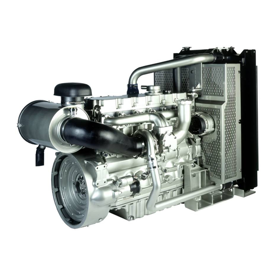
SEBU8387 Product Information Section Model Views Model Views i02649396 Model View Illustrations The following model views show typical features of the engine. Due to individual applications, your engine may appear different from the illustrations. Note: Only major components are identified on the following illustrations. -
Page 19: Engine Description
SEBU8387 Product Information Section Model Views g01329941 Illustration 17 Rear right engine view (16) Oil gauge (21) Exhaust manifold (26) Oil pan (17) Air intake (22) Exhaust elbow (27) Drain plug (oil) (18) Oil filler (23) Turbocharger (28) Drain plug or coolant sampling valve (19) Front lifting eye (24) Wastegate solenoid (29) Breather... -
Page 20: Engine Cooling And Lubrication
SEBU8387 Product Information Section Model Views • Automatic air/fuel ratio control • Torque rise shaping • Injection timing control • System diagnostics For more information on electronic engine features, refer to the Operation and Maintenance Manual, “Features and Controls” topic (Operation Section). Engine Diagnostics The engine has built-in diagnostics in order to ensure g01127295... - Page 21 SEBU8387 Product Information Section Model Views Engine efficiency, efficiency of emission controls, and engine performance depend on adherence to proper operation and maintenance recommendations. Engine performance and efficiency also depend on the use of recommended fuels, lubrication oils, and coolants. Refer to this Operation and Maintenance Manual, “Maintenance Interval Schedule”...
-
Page 22: Product Identification Information
Illustration 19 Make a copy of this list for a record. Keep the information for future reference. Location of the serial number plate Perkins engines are identified by an engine serial Record for Reference number. Engine Model _________ ______________________________________ An example of an engine number is PK*****U000001J. -
Page 23: Emissions Certification Film
SEBU8387 Product Information Section Product Identification Information Fan Drive Belt _________ _____________________________________ Alternator Belt _________ _____________________________________ i02648170 Emissions Certification Film Label for compliant engines Typical examples of emissions labels g01329012 Illustration 21... -
Page 24: Operation Section
Engine Lifting fixtures obsolete. If alterations are made, ensure that correct lifting devices are provided. Consult your Perkins dealer or your Perkins distributor for information regarding fixtures for correct engine lifting. i02308881... - Page 25 SEBU8387 Operation Section Lifting and Storage 9. If equipped, replace the crankcase breather element. Seal the end of the breather pipe. Personal injury can result from hot coolant. Any 10. Remove the valve mechanism cover. Spray contact with hot coolant or with steam can cause 1762811 POWERPART Lay-Up 2 around the severe burns.
-
Page 26: Gauges And Indicators
If the engine is operating above the normal range Determine and correct the cause of any significant and steam becomes apparent, perform the following change in the readings. Consult your Perkins dealer procedure: or your Perkins distributor for assistance. 1. Reduce the load and the engine rpm. - Page 27 SEBU8387 Operation Section Gauges and Indicators Service Hour Meter – The gauge indicates total operating hours of the engine.
-
Page 28: Features And Controls
Indicator Lamps. For more information or assistance for repairs, consult If the Warning/Derate/Shutdown mode has been your Perkins dealer or your Perkins distributor. selected and the warning indicator activates, bring the engine to a stop whenever possible. De- pending on the application, special precautions should be taken to avoid personal injury. -
Page 29: Sensor Locations
SEBU8387 Operation Section Features and Controls i02296746 Monitoring System Table 2 Warning Shutdown Lamp Status Description of lamp status Engine Status Lamp Lamp Lamp check When the engine start switch is turned to the The engine has not been “ON” position both lamps will illuminate for 2 started. - Page 30 SEBU8387 Operation Section Features and Controls g01330217 Illustration 23 (1) Coolant temperature sensor (4) Fuel pressure sensor (7) Primary position sensor (2) Intake manifold air temperature sensor (5) Electronic control module (ECM) (8) Secondary position sensor (3) Intake manifold pressure sensor (6) Oil pressure sensor...
- Page 31 SEBU8387 Operation Section Features and Controls g01330220 Illustration 24 (1) Coolant temperature sensor (3) Intake manifold pressure sensor (5) Electronic control module (ECM) (2) Intake manifold air temperature sensor (4) Fuel pressure sensor g01330325 Illustration 25 (6) Engine oil pressure sensor (7) Primary speed/timing sensor (8) Secondary speed/timing sensor...
-
Page 32: Fuel Pressure Sensor
SEBU8387 Operation Section Features and Controls Failure of the Coolant Temperature Illustration 24 and illustration 25 shows the sensors and the ECM in position on the engine. Sensor Failure of Sensors The ECM (5) will detect a failure of the coolant temperature sensor. - Page 33 SEBU8387 Operation Section Features and Controls Secondary Speed/Timing Sensor 8 Very Low Oil Pressure Warning The very low oil pressure setpoint is dependent The signal from the secondary speed/timing sensor upon the engine speed. If the DERATE mode of the is used by the ECM (5) on engine start-up in order engine monitoring system is selected, the ECM (5) to check the stroke of the pistons.
-
Page 34: Engine Diagnostics
Retrieval i02651093 Self-Diagnostics “Diagnostic” Lamp Perkins electronic engines have the capability to Use the “DIAGNOSTIC” lamp or an electronic service perform a self-diagnostics test. When the system tool to determine the diagnostic flash code. detects an active problem, a diagnostic lamp is activated. - Page 35 SEBU8387 Operation Section Engine Diagnostics Table 3 Flash Codes for 1106C Genset Diagnostic Effect On Engine Performance Suggested Operator Flash Code Action Description Engine Reduced Engine Service Schedule Misfire Power Engine Shutdown a Service. Speed No. 1 Injector Fault No. 2 Injector Fault No.
-
Page 36: Fault Logging
SEBU8387 Operation Section Engine Diagnostics (Table 3, contd) Ignition Key Switch Fault SAE J1939 Data Link Fault 5 Volt Sensor DC Power Supply Fault 8 Volt Sensor DC Power Supply Fault Customer/System Parmeter Fault If warning lamps are installed refer to this table. For installations that have electronic displays, refer to the OEM for information. An “X”... - Page 37 SEBU8387 Operation Section Engine Diagnostics i01902995 Engine Operation with Intermittent Diagnostic Codes If a diagnostic lamp illuminates during normal engine operation and the diagnostic lamp shuts off, an intermittent fault may have occurred. If a fault has occurred, the fault will be logged into the memory of the Electronic Control Module (ECM).
-
Page 38: Engine Starting
SEBU8387 Operation Section Engine Starting Engine Starting i02322203 Starting the Engine i02322201 Before Starting Engine Note: Do not adjust the engine speed control during start-up. The electronic control module (ECM) will control the engine speed during start-up. Before the engine is started, perform the required daily maintenance and any other periodic Starting the Engine maintenance that is due. -
Page 39: Starting With Jump Start Cables
SEBU8387 Operation Section Engine Starting When Group 2 diesel fuel is used, the following items i02322204 provide a means of minimizing starting problems Starting with Jump Start and fuel problems in cold weather: Engine oil pan Cables heaters, jacket water heaters, fuel heaters, and fuel line insulation. -
Page 40: After Starting Engine
SEBU8387 Operation Section Engine Starting 3. Connect one negative end of the jump start cable to the negative cable terminal of the electrical source. Connect the other negative end of the jump start cable to the engine block or to the chassis ground. -
Page 41: Engine Operation
Fuel Conservation Practices i02330143 Engine Operation The efficiency of the engine can affect the fuel economy. Perkins design and technology in manufacturing provides maximum fuel efficiency in all applications. Follow the recommended procedures Correct operation and maintenance are key factors... -
Page 42: Engine Stopping
SEBU8387 Operation Section Engine Stopping Engine Stopping i02330274 After Stopping Engine i02334873 Stopping the Engine Note: Before you check the engine oil, do not operate the engine for at least 10 minutes in order to allow the engine oil to return to the oil pan. NOTICE Stopping the engine immediately after it has been working under load, can result in overheating and ac-... - Page 43 SEBU8387 Operation Section Engine Stopping • Check the coolant for correct antifreeze protection and the correct corrosion protection. Add the correct coolant/water mixture, if necessary. • Perform all required periodic maintenance on all driven equipment. This maintenance is outlined in the instructions from the OEM.
-
Page 44: Cold Weather Operation
“Starting with Jump Start Cables.” for instructions. Recommendations from your Perkins dealer or Viscosity of the Engine Lubrication your Perkins distributor are based on past proven practices. The information that is contained in this section provides guidelines for cold weather operation. -
Page 45: Idling The Engine
This fuel and oil causes soft carbon deposits to form on the valve stems. Note: Perkins discourages the use of all air flow Generally, the deposits do not cause problems and restriction devices such as radiator shutters. - Page 46 Insulating the Air Inlet and Engine Compartment Note: Only use grades of fuel that are recommended by Perkins. Refer to this Operation and Maintenance When temperatures below −18 °C (−0 °F) will be Manual, “Fluid Recommendations”. frequently encountered, an air cleaner inlet that...
-
Page 47: Fuel Filters
SEBU8387 Operation Section Cold Weather Operation i02323237 Fuel Related Components in Cold Weather Fuel Tanks Condensation can form in partially filled fuel tanks. Top off the fuel tanks after you operate the engine. Fuel tanks should contain some provision for draining water and sediment from the bottom of the tanks. -
Page 48: Lubrication System
American Petroleum Institute (API) is recognized Imp gal) Imp gal) by Perkins. For detailed information about this These values are the approximate capacities for the crankcase system, see the latest edition of the “API publication oil sump (aluminum) which includes the standard factory No. -
Page 49: Engine Oil
API CH-4 oils may be classifications are developed in order to provide used in Perkins engines that use API CG-4 and API commercial lubricants for a broad range of diesel CF-4 oils. API CH-4 oils will generally exceed the engines that operate at various conditions. - Page 50 Choose an oil with the highest TBN that meets one intervals. API CH-4 oils are recommended for of these classifications: EMA DHD-1 and API CH-4. conditions that demand a premium oil. Your Perkins distributor has specific guidelines for optimizing oil •...
-
Page 51: Aftermarket Oil Additives
Re-refined base stock oils are acceptable for use in Perkins engines if these oils meet the Refer to Table 8 (maximum temperature) in order to performance requirements that are specified by select the oil viscosity for engine operation at the Perkins. - Page 52 finished oil. The aftermarket additive could fail to mix with the finished oil. This could produce sludge in the crankcase. Perkins discourages the use of aftermarket additives in finished oils. To achieve the best performance from a Perkins engine, conform to the following guidelines: •...
-
Page 53: Maintenance Interval Schedule
SEBU8387 Maintenance Section Maintenance Interval Schedule Every 1000 Service Hours i02761000 Maintenance Interval Schedule Engine Valve Lash - Inspect/Adjust ...... 70 Water Pump - Inspect ........... 86 Every 2000 Service Hours When Required Aftercooler Core - Inspect ........54 Battery - Replace ..........56 Alternator - Inspect .......... -
Page 54: Every 2000 Service Hours Aftercooler Core - Inspect
SEBU8387 Maintenance Section Aftercooler Core - Clean/Test i02322260 Aftercooler Core - Clean/Test Personal injury can result from air pressure. Personal injury can result without following prop- er procedure. When using pressure air, wear a pro- 1. Remove the core. Refer to the OEM information tective face shield and protective clothing. -
Page 55: Alternator And Fan Belts - Inspect
Make repairs, if necessary. i02322311 Alternator - Inspect Perkins recommends a scheduled inspection of the alternator. Inspect the alternator for loose connections and correct battery charging. Check the ammeter (if equipped) during engine operation in order to ensure correct battery performance and/or correct performance of the electrical system. -
Page 56: Battery - Replace
SEBU8387 Maintenance Section Battery - Replace 8. Connect the NEGATIVE “-” cable to the NEGATIVE i02322315 “-” battery terminal. Battery - Replace i02747977 Battery Electrolyte Level - Check Batteries give off combustible gases which can explode. A spark can cause the combustible gas- es to ignite. -
Page 57: Battery Or Battery Cable - Disconnect
SEBU8387 Maintenance Section Battery or Battery Cable - Disconnect i02323088 i02238072 Battery or Battery Cable - Cooling System Coolant (Commercial Heavy-Duty) - Disconnect Change NOTICE The battery cables or the batteries should not be Care must be taken to ensure that fluids are contained removed with the battery cover in place. - Page 58 The full distillation 3. Start and run the engine at low idle. Increase the procedure is the only method acceptable by Perkins to engine rpm to high idle. Run the engine at high reclaim the coolant.
-
Page 59: Every 12 000 Service Hours Or 6 Years Cooling System Coolant (Elc) - Change
The fuel has entered the cooling system and the for reuse in engine cooling systems. The full distillation coolant is contaminated. procedure is the only method acceptable by Perkins to reclaim the coolant. Note: When the cooling system is cleaned, only... -
Page 60: Cooling System Coolant Level - Check
Note: The cooling system may not have been Cooling system air locks may result in engine damage. provided by Perkins. The procedure that follows is for typical cooling systems. Refer to the OEM 2. Fill the cooling system with Extended Life information for the correct procedures. -
Page 61: Engines Without A Coolant Recovery Tank
SEBU8387 Maintenance Section Cooling System Coolant Level - Check Pressurized System: Hot coolant can cause seri- ous burns. To open the cooling system filler cap, stop the engine and wait until the cooling system components are cool. Loosen the cooling system pressure cap slowly in order to relieve the pres- sure. -
Page 62: Cooling System Supplemental Coolant Additive (Sca) - Test/Add
SEBU8387 Maintenance Section Cooling System Supplemental Coolant Additive (SCA) - Test/Add 1. Slowly loosen the cooling system filler cap in i02335389 order to relieve the pressure. Remove the cooling Cooling System Supplemental system filler cap. Coolant Additive (SCA) - Note: Always discard drained fluids according to Test/Add local regulations. -
Page 63: Engine - Clean
SEBU8387 Maintenance Section Driven Equipment - Check i01909392 Engine - Clean Personal injury or death can result from high volt- age. Moisture can create paths of electrical conductiv- ity. Make sure that the electrical system is OFF. Lock out the starting controls and tag the controls “DO NOT OPERATE”. -
Page 64: Engine Air Cleaner Element (Dual Element)
Servicing the Air Cleaner Elements Note: The air filter system may not have been provided by Perkins. The procedure that follows is for a typical air filter system. Refer to the OEM information for the correct procedure. -
Page 65: Cleaning The Primary Air Cleaner Elements
SEBU8387 Maintenance Section Engine Air Cleaner Element (Dual Element) - Clean/Replace Cleaning the Primary Air Cleaner Pressurized Air Elements Refer to the OEM information in order to determine Personal injury can result from air pressure. the number of times that the primary filter element can be cleaned. -
Page 66: Engine Air Cleaner Element (Single Element)
SEBU8387 Maintenance Section Engine Air Cleaner Element (Single Element) - Inspect/Replace Note: Refer to “Inspecting the Primary Air Cleaner Elements”. NOTICE Never service the air cleaner element with the engine Inspecting the Primary Air Cleaner running since this will allow dirt to enter the engine. Elements A wide variety of air cleaners may be installed for use with this engine. -
Page 67: Engine Air Precleaner - Check/Clean
Check for ease of resetting. The service indicator should reset in less than three pushes. Note: The engine mounts may not have been supplied by Perkins. Refer to the OEM information • Check the movement of the yellow core when... -
Page 68: Engine Oil Sample - Obtain
filter head or the oil sampling valve is positioned on the cylinder block. Perkins recommends using a sampling valve in order Hot oil and hot components can cause personal to obtain oil samples. The quality and the consistency injury. -
Page 69: Replace The Oil Filter
fications. Use of an oil filter that is not recommended stopped. Drain the oil pan with the oil warm. This by Perkins could result in severe damage to the en- draining method allows the waste particles that are gine bearings, crankshaft, etc., as a result of the larger suspended in the oil to be drained properly. -
Page 70: Fill The Oil Pan
Operation and Maintenance Manual, maintenance. Refer to the Service Manual or your au- “Refill Capacities” for more information on refill thorized Perkins dealer or your Perkins distributor for capacities. the complete valve lash adjustment procedure. Operation of Perkins engines with incorrect valve lash can reduce engine efficiency, and also reduce engine... -
Page 71: Every 500 Service Hours Fan Clearance - Check
SEBU8387 Maintenance Section Fan Clearance - Check Ensure that the engine can not be started while this maintenance is being performed. To help pre- vent possible injury, do not use the starting motor to turn the flywheel. Hot engine components can cause burns. Allow additional time for the engine to cool before mea- suring/adjusting valve lash clearance. -
Page 72: Fuel System - Prime
SEBU8387 Maintenance Section Fuel System - Prime g01348394 Illustration 46 Adjustment of the cover will change the clearance Refer to the Operation and Maintenance Manual , (gap) between the edge of the cover and the tip of “General Hazard Information and High Pressure Fuel the fan blade. -
Page 73: Hand Fuel Priming Pump
SEBU8387 Maintenance Section Fuel System - Prime • The fuel tank is empty or the fuel tank has been partially drained. Contact with high pressure fuel may cause fluid • The low pressure fuel lines are disconnected. penetration and burn hazards. High pressure fu- el spray may cause a fire hazard. - Page 74 SEBU8387 Maintenance Section Fuel System Primary Filter/Water Separator - Drain Contact with high pressure fuel may cause fluid penetration and burn hazards. High pressure fu- el spray may cause a fire hazard. Failure to fol- low these inspection, maintenance and service in- structions may cause personal injury or death.
-
Page 75: Fuel System Primary Filter/Water Separator
SEBU8387 Maintenance Section Fuel System Primary Filter (Water Separator) Element - Replace 2. Open drain (1). Allow the fluid to drain into the container. 3. Tighten drain (1) by hand pressure only. Remove the tube and dispose of the drained fluid in a safe place. -
Page 76: Type Two Filter
SEBU8387 Maintenance Section Fuel System Primary Filter (Water Separator) Element - Replace Type Two Filter Fuel leaked or spilled onto hot surfaces or elec- trical components can cause a fire. To help pre- vent possible injury, turn the start switch off when changing fuel filters or water separator elements. - Page 77 SEBU8387 Maintenance Section Fuel System Primary Filter (Water Separator) Element - Replace g01370515 g01370722 Illustration 52 Illustration 53 Typical example Typical example 3. Install a suitable tube onto the drain (1). Open the 6. Rotate the bowl (3) counterclockwise in order to drain (1).
- Page 78 SEBU8387 Maintenance Section Fuel System Primary Filter (Water Separator) Element - Replace g01370724 g01371107 Illustration 54 Illustration 55 Typical example Typical example 7. Use a suitable tool in order to remove the old 8. Lubricate the O ring seal (5 ) with clean engine oil canister (4).
-
Page 79: Fuel System Secondary Filter - Replace
SEBU8387 Maintenance Section Fuel System Secondary Filter - Replace After the engine has stopped, you must wait for i02690522 60 seconds in order to allow the fuel pressure to Fuel System Secondary Filter - be purged from the high pressure fuel lines before Replace any service or repair is performed on the engine fuel lines. -
Page 80: Type Two Filter
SEBU8387 Maintenance Section Fuel System Secondary Filter - Replace Type Two filter 1. Ensure that the fuel supply valve (if equipped) is in the OFF position. Place a suitable container under the fuel filter in order to catch any fuel that might spill. -
Page 81: Drain
SEBU8387 Maintenance Section Fuel Tank Water and Sediment - Drain Some fuel tanks use supply pipes that allow water i02335436 and sediment to settle below the end of the fuel Fuel Tank Water and Sediment supply pipe. Some fuel tanks use supply lines that - Drain take fuel directly from the bottom of the tank. -
Page 82: Radiator - Clean
Anticipated expansion and contraction of the fittings Replace the Hoses and the Clamps The radiator is not usually supplied by Perkins. The following text describes a typical cleaning procedure Refer to the OEM information for further information for the radiator. Refer to the OEM information for on removing and replacing fuel hoses (if equipped). -
Page 83: Severe Service Application - Check
Refer to the standards for the engine or consult your Perkins dealer or your Perkins distributor in order to Pressurized water may also be used for cleaning. determine if the engine is operating within the defined The maximum water pressure for cleaning purposes parameters. -
Page 84: Incorrect Operating Procedures
Test” for more information on the checking procedure or removed for the cleaning of the compressor. and for specifications or consult your Perkins dealer or your Perkins distributor for assistance. 1. Remove the pipe from the turbocharger exhaust... -
Page 85: Walk-Around Inspection
Ensure that all Remove and Install”. For more information, consult clamps are installed correctly and that all clamps your Perkins dealer or your Perkins distributor. are tightened securely. • Inspect the lubrication system for leaks at the front... -
Page 86: Water Pump - Inspect
SEBU8387 Maintenance Section Water Pump - Inspect If you inspect the engine in operation, always use the proper inspection procedure in order to avoid a fluid penetration hazard. Refer to Operation and Maintenance Manual, “General hazard Information”. Visually inspect the high pressure fuel lines for damage or signs of fuel leakage. -
Page 87: Warranty Section
Emissions Warranty. Consult your authorized Perkins dealer or your authorized Perkins distributor in order to determine if your engine is emissions certified and if your engine is subject to an Emissions Warranty. -
Page 88: Index
SEBU8387 Index Section Index Electrical System ........... 14 After Starting Engine ..........40 Grounding Practices .......... 15 After Stopping Engine..........42 Aftercooler Core - Clean/Test ........ 54 Emergency Stopping ..........42 Aftercooler Core - Inspect........54 Emissions Certification Film ........23 Alternator - Inspect .......... - Page 89 SEBU8387 Index Section Foreword ..............4 California Proposition 65 Warning ....... 4 Literature Information........... 4 Maintenance Interval Schedule ......53 Maintenance ............4 Maintenance Section ..........48 Maintenance Intervals.......... 4 Model View Illustrations......... 18 Model Views ............18 Operation ............. 4 Monitoring System...........
- Page 90 SEBU8387 Index Section Starting the Engine ..........38 Starting the Engine ..........38 Starting with Jump Start Cables ......39 Stopping the Engine ..........42 Table of Contents............. 3 Turbocharger - Inspect .......... 84 Inspecting............84 Removal and Installation........84 Walk-Around Inspection ........
- Page 91 Product and Dealer Information Note: For product identification plate locations, see the section “Product Identification Information” in the Operation and Maintenance Manual. Delivery Date: Product Information Model: Product Identification Number: Engine Serial Number: Transmission Serial Number: Generator Serial Number: Attachment Serial Numbers: Attachment Information: Customer Equipment Number: Dealer Equipment Number:...
- Page 92 Copyright © 2007 Perkins Engine Company Limited Printed in U. K . All Rights Reserved...