Dean D Service & Parts Manual
Decathlon series gas fryers
Hide thumbs
Also See for D:
- Service and parts manual (100 pages) ,
- Installation & operation manual (52 pages)
Table of Contents
Advertisement
D, CFD, SCFD, FPD Models
NON-CE &
Dean, a member of the Commercial Food Equipment Service Association, recommends using
CFESA Certified Technicians.
OCTOBER 2006
*8195922*
24-Hour Service Hotline
1-800-551-8633
PDF compression, OCR, web optimization using a watermarked evaluation copy of CVISION PDFCompressor
Advertisement
Table of Contents
Troubleshooting

Related Manuals for Dean D


Summary of Contents for Dean D
- Page 1 D, CFD, SCFD, FPD Models NON-CE & Dean, a member of the Commercial Food Equipment Service Association, recommends using CFESA Certified Technicians. OCTOBER 2006 *8195922* 24-Hour Service Hotline 1-800-551-8633 PDF compression, OCR, web optimization using a watermarked evaluation copy of CVISION PDFCompressor...
- Page 2 If, during the warranty period, the customer uses a part for this Enodis equipment other than an unmodified new or recycled part purchased directly from Frymaster and Dean, or any of its authorized service centers, and/or the part being used is modified from its original configuration, this warranty will be void.
- Page 3 WARNING No structural material on the fryer should be altered or removed to accommodate placement of the fryer under a hood. Questions? Call the Frymaster and Dean Service Hotline at 1-800-551- 8633. This equipment is to be installed in compliance with the basic plumbing code of The Building Officials and Code Administrators International, Inc.
-
Page 4: Table Of Contents
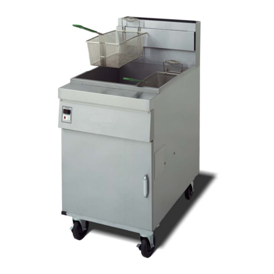
Decathlon Series Gas Fryers Service and Parts Manual TABLE OF CONTENTS SERVICE PROCEDURES……..……..……………………………………………... Functional Description....................1-1 Accessing Fryers for Service...................1-8 Cleaning the Gas Valve Vent Tube (if applicable)..........1-10 Adjusting Burner Manifold Gas Pressure............1-10 Adjusting the Pilot Flame..................1-11 Calibrating the Thermatron Controller and Backup Thermostat....1-11 Replacing Fryer Components................1-13 Troubleshooting and Problem Isolation..............1-32 Troubleshooting Guides..................1-41... - Page 5 FINDING YOUR WAY AROUND THE DEAN DECATHLON Basket Hanger Flue Cap Frypot Top Cap Electronic Operating Thermostat Burners Drain Tubes Drain Valve Handle (Red) Filter Unit Oil Return Handle (Yellow) Drain Flush Handle (Blue) Drain Tubes PDF compression, OCR, web optimization using a watermarked evaluation copy of CVISION PDFCompressor...
-
Page 6: Service Procedures
DECATHLON SERIES GAS FRYERS CHAPTER 1: SERVICE PROCEDURES 1.1 Functional Description Decathlon Series gas fryers contain a welded steel frypot (stainless or cold-rolled) heated by gas flames diffused evenly through tubes built into the frypot. Flames originate from orifices in a burner manifold positioned beneath cast-iron burners. The burners are positioned in the tube openings, at the front of the frypot. - Page 7 DECATHLON SERIES GAS FRYERS CHAPTER 1: SERVICE PROCEDURES 1.1 Functional Description (cont.) An electromechanical gas valve regulates gas flow to the manifold. Decathlon Series gas fryers are equipped with either a 120V valve system or a 24V valve system. Unit configurations include either a pilot ignition system (standing pilot) or an electronic ignition system.
- Page 8 DECATHLON SERIES GAS FRYERS CHAPTER 1: SERVICE PROCEDURES Electronic Ignition Configuration (cont.) The module contains a 60-second time delay circuit and a coil that activates the gas valve. The ignitor assembly consists of a spark plug, a pilot, and a flame sensor element. At start-up the ON/OFF switch is placed in the ON position, supplying 12 VDC to the heat control circuitry in the controller or computer and to one side of the heat relay coil on the interface board.
- Page 9 DECATHLON SERIES GAS FRYERS CHAPTER 1: SERVICE PROCEDURES Interface Boards The interface board provides a link between the controller/computer and the fryer’s individual components without requiring excessive wiring, and allows the controller to execute commands from one central point. Two types of interface boards may be used in Decathlon Series gas fryers; the type used depends on the fryer configuration.
- Page 10 DECATHLON SERIES GAS FRYERS CHAPTER 1: SERVICE PROCEDURES Interface Boards (cont.) IFB 106-6669 & 106-6710: These interface boards are used in Decathlon fryers with Frymaster computer control systems. INTERFACE BOARD P/N 106-6669 INTERFACE BOARD P/N 106-6710 PDF compression, OCR, web optimization using a watermarked evaluation copy of CVISION PDFCompressor...
- Page 11 DECATHLON SERIES GAS FRYERS CHAPTER 1: SERVICE PROCEDURES Interface Boards (cont.) FREQUENTLY USED TEST POINTS FOR INTERFACE BOARD P/N 806-4549 (previous style) Test Meter Setting Pins Test Results 12VAC Power to Controller 50VAC Scale 1 and 3 on J3 12-18 24VAC Power to Right Module 50VAC Scale 8 on J3 and GROUND...
-
Page 12: Interface Board
DECATHLON SERIES GAS FRYERS CHAPTER 1: SERVICE PROCEDURES Interface Boards (cont.) INTERFACE BOARD 12 VAC TO CPTR J3 PIN 3 GROUND GROUND 12 VAC RETURN J3 PIN 1 COMPUTER RT HT RELAY (K3) COMPUTER 12 VDC TO RELAYS LT HT RELAY (K2) COMPUTER * Twin Vat configurations ** Single Vat configurations... -
Page 13: Accessing Fryers For Servicing
DANGER No structural material on the fryer should be altered or removed to accommodate placement of the fryer under a hood. Questions? Call the Frymaster Dean Service Hotline at 1-800-551-8633. PDF compression, OCR, web optimization using a watermarked evaluation copy of CVISION PDFCompressor... - Page 14 DECATHLON SERIES GAS FRYERS CHAPTER 1: SERVICE PROCEDURES Restraints Once the fryer has been positioned at the frying station, use a carpenter’s level placed across the top of the frypot to verify that the unit is level, both side-to-side and front-to-back. To level fryers equipped with legs, the bottom of the legs can be screwed out up to one inch for leveling.
-
Page 15: Cleaning The Gas Valve Vent Tube (If Applicable)
DECATHLON SERIES GAS FRYERS CHAPTER 1: SERVICE PROCEDURES 1.3 Cleaning the Gas Valve Vent Tube (if applicable) 1. Set the fryer power switch and the gas valve to the OFF position. 2. Carefully unscrew the vent tube from the gas valve. NOTE: The vent tube may be straightened for ease in removal. -
Page 16: Adjusting The Pilot Flame
DECATHLON SERIES GAS FRYERS CHAPTER 1: SERVICE PROCEDURES 1.5 Adjusting the Pilot Flame 1.5.1 Main Pilot 1. Remove the cap from the pilot adjustment screw hole on the gas valve. 2. Using a small, flat-tipped screwdriver, turn the pilot adjusting screw counterclockwise to increase length of flame or clockwise to decrease length of flame. - Page 17 DECATHLON SERIES GAS FRYERS CHAPTER 1: SERVICE PROCEDURES 1.6.2 Backup Operating Thermostat (Optional) 1. Fill the frypot to the lower OIL-LEVEL line with oil. If solid shortening is used, it must be melted before starting the calibration procedure. 2. Light the pilot. 3.
-
Page 18: Replacing Fryer Components
DECATHLON SERIES GAS FRYERS CHAPTER 1: SERVICE PROCEDURES 1.7 Replacing Fryer Components 1.7.1 Replacing the Computer 1. Disconnect the fryer from the electrical supply. 2. Unscrew the two computer panel screws. The computer panel is hinged at the bottom and will swing open from the top. Computer panel in “down”... - Page 19 DECATHLON SERIES GAS FRYERS CHAPTER 1: SERVICE PROCEDURES 1.7.2 Replacing the Backup Thermostat (if applicable) 1. Disconnect the fryer from the electrical supply. 2. Drain cooking oil from frypot. 3. Remove thermostat knob. 4. Disconnect the wiring plug(s) from the component shield/control box. 5.
- Page 20 2. Drain cooking oil from the frypot. Allow the frypot to cool completely before proceeding. 3. Remove the fryer door for easier access to the temperature probe. D models: Lift door up, disengage rod from lower door bracket, and remove door.
- Page 21 DECATHLON SERIES GAS FRYERS CHAPTER 1: SERVICE PROCEDURES 1.7.3 Replacing the Temperature Probe; Computer-equipped Fryers (cont.) 6. Remove the appropriate burners to gain access to the temperature probe. (See Steps 20-22 on page 1-27 for more details.) NOTE: Ensure that the burners are placed in their original spots when putting them back into the fryer.
- Page 22 2. Perform steps 1-4 in Section 1.7.1, Replacing the Computer. 3. Remove the fryer door for easier access to the temperature probe. D models: Lift door up, disengage rod from lower door bracket, and remove door. CFD/SCFD/FPD models: Remove the top bracket and hinge, then remove door.
- Page 23 DECATHLON SERIES GAS FRYERS CHAPTER 1: SERVICE PROCEDURES 1.7.4 Replacing the High-limit Thermostat (cont.) 4. Remove two screws securing the high-limit mounting-bracket. Do not disconnect wires from high-limit at this time. Remove screws (arrows) securing high-limit to fryer. 5. Loosen and completely unscrew the compression nut, then the pass-through nut on the frypot bottom.
- Page 24 DECATHLON SERIES GAS FRYERS CHAPTER 1: SERVICE PROCEDURES 1.7.4 Replacing the High-limit Thermostat (cont.) 7. Carefully pull high-limit capillary tube and bulb out of the frypot from the bottom. Remove high-limit capillary tube and bulb from the bottom of the frypot. 8.
- Page 25 DECATHLON SERIES GAS FRYERS CHAPTER 1: SERVICE PROCEDURES 1.7.4 Replacing the High-limit Thermostat (cont.) 9. Remove high-limit from fryer by pulling the capillary tube and bulb through the component box opening (arrow). This may require removal of the control panel frame. 10.
- Page 26 DECATHLON SERIES GAS FRYERS CHAPTER 1: SERVICE PROCEDURES 1.7.5 Replacing Rocker Switches (cont.) 3. Depress the retaining clips (see illustration below) and push the switch out of the slot. If there is a switch-guard present, retain it for installation of the replacement switch. Depress clips on each side to remove switch from control panel.
- Page 27 3. Unplug fryer from electrical supply source. 4. Remove the fryer door for easier access to the temperature probe. D models: Lift door up, disengage rod from lower door bracket, and remove door. CFD/SCFD/FPD models: Remove the top bracket and hinge, then remove door.
- Page 28 DECATHLON SERIES GAS FRYERS CHAPTER 1: SERVICE PROCEDURES 1.7.8 Replacing the Frypot (cont.) 6. Carefully pry the capping strip off with a screwdriver or similar tool and set aside. Be careful not to bend the capping strip during removal. Removing capping strip. 7.
- Page 29 DECATHLON SERIES GAS FRYERS CHAPTER 1: SERVICE PROCEDURES 1.7.8 Replacing the Frypot (cont.) 10. Remove screws securing flue-cap braces to frypot (a nut-driver with an extension or long screwdriver is required). Use care not to drop the screws into the flues. If this happens, the screws can be retrieved when the flue is removed (Step 16).
- Page 30 DECATHLON SERIES GAS FRYERS CHAPTER 1: SERVICE PROCEDURES 1.7.8 Replacing the Frypot (cont.) 13. Remove steel line from oil-return valve and nipple by loosening flare fittings on both ends. Hold backup with an adjustable wrench when removing fittings. (Prior to removal, absorbent cloth or paper towels should be placed under the oil line to catch any oil remaining in the lines.) Holding backup while unscrewing flare nut on...
- Page 31 DECATHLON SERIES GAS FRYERS CHAPTER 1: SERVICE PROCEDURES 1.7.8 Replacing the Frypot (cont.) 18. If fryer is equipped with a front drain manifold, disconnect manifold at slip-nut fitting and remove. On front drain manifolds, disconnect the slip-nut fitting (arrow) to remove. 19.
- Page 32 DECATHLON SERIES GAS FRYERS CHAPTER 1: SERVICE PROCEDURES 1.7.8 Replacing the Frypot (cont.) 20. Remove the burner shield. Loosen burner bolts (two per burner) that secure burners to the burner support rail. NOTE: On most fryers, do not remove bolts from burners.
- Page 33 DECATHLON SERIES GAS FRYERS CHAPTER 1: SERVICE PROCEDURES 1.7.8 Replacing the Frypot (cont.) Each burner is unique in the flame-transfer-hole configuration and must be reinstalled correctly: Left burners (L): Flame transfer hole is on the right side of the burner head. Center burners (C): Flame transfer hole is on both sides of the burner head.
- Page 34 DECATHLON SERIES GAS FRYERS CHAPTER 1: SERVICE PROCEDURES 1.7.8 Replacing the Frypot (cont.) 23. Remove screw(s) securing the electronic or standing pilot bracket to the frypot bracket. Reposition ignitor assembly down and away from frypot. Use care not to bend, kink, or damage the electronic ignition lines and wiring.
- Page 35 DECATHLON SERIES GAS FRYERS CHAPTER 1: SERVICE PROCEDURES 1.7.8 Replacing the Frypot (cont.) 27. Remove the temperature probe from frypot. (See Section 1.7.3, Replacing the Temperature Probe: Computer –equipped Fryers, for specific instructions.) 28. Remove the high-limit and backup thermostats. Follow Steps 5-7, Section 1.7.4, Replacing the High-limit Thermostat, and Section 1.7.2, Replacing Backup Thermostat, (where applicable) from frypot.
- Page 36 DECATHLON SERIES GAS FRYERS CHAPTER 1: SERVICE PROCEDURES 1.7.8 Replacing the Frypot (cont.) 31. Using a sharp knife or box-cutter, cut the silicon seal between and in front of the two frypots (two-vat or more). Use care not to scratch stainless steel surfaces. Cutting frypot seal prior to frypot removal.
-
Page 37: Troubleshooting And Problem Isolation
DECATHLON SERIES GAS FRYERS CHAPTER 1: SERVICE PROCEDURES 1.8 Troubleshooting and Problem Isolation Because it is not feasible to include every issue that might occur, this section is intended to provide technicians with a general knowledge of the broad problem categories associated with this equipment and the probable causes of each. - Page 38 DECATHLON SERIES GAS FRYERS CHAPTER 1: SERVICE PROCEDURES 1.8.1 Ignition Failure (cont.) The Electronic Circuits If gas and electrical power are supplied to the fryer, the next most likely cause of ignition failure is a problem in the 24 VAC circuit of fryers equipped with electronic ignition systems, or in the pilot system for those without electronic ignition.
- Page 39 DECATHLON SERIES GAS FRYERS CHAPTER 1: SERVICE PROCEDURES 1.8.2 Improper Burner Function (cont.) If popping occurs only during peak operating hours, the problem may be incorrect or fluctuating gas pressure. Verify that the incoming gas pressure (pressure to the gas valve) is in accordance with the appropriate CE or Non-CE requirements listed in the Installation and Operation manual that came with the fryer, and that the pressure remains constant throughout all hours of usage.
- Page 40 DECATHLON SERIES GAS FRYERS CHAPTER 1: SERVICE PROCEDURES 1.8.2 Improper Burner Function (cont.) Burners lighting on the left side only may be caused by a trailing pilot problem (four- and five-tube frypots) or improper burner manifold pressure. Fluctuating flame intensity is normally caused by either improper or fluctuating incoming gas pressure, but may also be the result of variations in the kitchen atmosphere.
- Page 41 DECATHLON SERIES GAS FRYERS CHAPTER 1: SERVICE PROCEDURES 1.8.4 Improper Computer Function Sensitivity or "Stretch Time." Sensitivity—or stretch time—is a programmable feature that increases the cook time countdown based on variations in the oil temperature from the setpoint (e.g., when cold product is dropped into the oil, causing the oil temperature to drop). The sensitivity for each product button has 10 settings (0 through 9).
- Page 42 DECATHLON SERIES GAS FRYERS CHAPTER 1: SERVICE PROCEDURES 1.8.5 Improper Filtration Function The majority of filtration problems arise from operator error. One of the most common errors is placing the filter paper on the bottom of the filter pan rather than over the filter screen. Anytime the pump is running, but no oil is being filtered, check the installation and size of the filter paper.
- Page 43 DECATHLON SERIES GAS FRYERS CHAPTER 1: SERVICE PROCEDURES 1.8.5 Improper Filtration Function (cont.) Incorrectly sized or installed paper will allow food particles and sediment to pass through and clog the suction tube on the bottom of the filter carriage. Particles large enough to block the suction tube may indicate that the crumb tray is not being used.
- Page 44 DECATHLON SERIES GAS FRYERS CHAPTER 1: SERVICE PROCEDURES 1.8.7 Improper Basket Lift Function Bell-Crank Basket Lifts Most Decathlon Series gas fryers are equipped with a bell- crank style basket lift. A cam and a bell crank are connected to the basket lift arm by a flat metal link. The cam is attached to a drive motor.
- Page 45 DECATHLON SERIES GAS FRYERS CHAPTER 1: SERVICE PROCEDURES 1.8.7 Improper Basket Lift Function Modular Basket Lifts Older Decathlon Series fryers may be equipped with modular basket lifts. The modular basket lift consists of a notched rod to which the basket lift arm is attached, a reversible- drive gear motor, and a pair of roller-activated microswitches.
-
Page 46: Troubleshooting Guides
(oil temperature is at least 15°F below Replace defective thermostat with a electronic/ operating thermostat known working thermostat. setting). D. Gas valve is suspect. D. Go to "No burner flame" section. 1-41 PDF compression, OCR, web optimization using a watermarked evaluation copy of CVISION PDFCompressor... - Page 47 C. Inspect gas valve and replace if thermopile/thermocouple are known defective. working, but burners fail to light. D. Gas valve is known to be good, but D. Inspect electronic/operating No burner flame. there is not 24 VAC (120VAC on thermostat sensor (while still in systems so equipped) at the gas valve frypot) for damage.
-
Page 48: Wiring Diagrams
DECATHLON SERIES GAS FRYERS CHAPTER 1: SERVICE PROCEDURES 1.10 Wiring Diagrams Note: The diagrams in this section depict wiring as of the date of manual publication. It may not reflect design changes made to the equipment after publication. Refer to the wiring diagram affixed to the unit when actually troubleshooting this equipment. - Page 49 DECATHLON SERIES GAS FRYERS CHAPTER 1: SERVICE PROCEDURES Decathlon, Dual Vat 1-44 PDF compression, OCR, web optimization using a watermarked evaluation copy of CVISION PDFCompressor...
- Page 50 DECATHLON SERIES GAS FRYERS CHAPTER 1: SERVICE PROCEDURES Thermatron, 24V 1-45 PDF compression, OCR, web optimization using a watermarked evaluation copy of CVISION PDFCompressor...
- Page 51 DECATHLON SERIES GAS FRYERS CHAPTER 1: SERVICE PROCEDURES Thermatron, 120V 1-46 PDF compression, OCR, web optimization using a watermarked evaluation copy of CVISION PDFCompressor...
- Page 52 DECATHLON SERIES GAS FRYERS CHAPTER 1: SERVICE PROCEDURES Transformer Box 1-47 PDF compression, OCR, web optimization using a watermarked evaluation copy of CVISION PDFCompressor...
- Page 53 DECATHLON SERIES GAS FRYERS CHAPTER 1: SERVICE PROCEDURES Decathlon Interface Board 1-48 PDF compression, OCR, web optimization using a watermarked evaluation copy of CVISION PDFCompressor...
- Page 54 DECATHLON SERIES GAS FRYERS CHAPTER 1: SERVICE PROCEDURES Dean Oil Return Wiring 1-49 PDF compression, OCR, web optimization using a watermarked evaluation copy of CVISION PDFCompressor...
- Page 55 DECATHLON SERIES GAS FRYERS CHAPTER 1: SERVICE PROCEDURES Single Decathlon with SUFF Filtration and Basket Lifts (PBI) 1-50 PDF compression, OCR, web optimization using a watermarked evaluation copy of CVISION PDFCompressor...
- Page 56 DECATHLON SERIES GAS FRYERS CHAPTER 1: SERVICE PROCEDURES Oil Return, Left-hand, Normally Open Float Switch 1-51 PDF compression, OCR, web optimization using a watermarked evaluation copy of CVISION PDFCompressor...
- Page 57 DECATHLON SERIES GAS FRYERS CHAPTER 1: SERVICE PROCEDURES Basket Lift, with Timer 1-52 PDF compression, OCR, web optimization using a watermarked evaluation copy of CVISION PDFCompressor...
- Page 58 DECATHLON SERIES GAS FRYERS CHAPTER 1: SERVICE PROCEDURES CM4-S with Constant Pilot 1-53 PDF compression, OCR, web optimization using a watermarked evaluation copy of CVISION PDFCompressor...
- Page 59 DECATHLON SERIES GAS FRYERS CHAPTER 1: SERVICE PROCEDURES Chili’s Wiring Diagram 1-54 PDF compression, OCR, web optimization using a watermarked evaluation copy of CVISION PDFCompressor...
- Page 60 DECATHLON SERIES GAS FRYERS CHAPTER 1: SERVICE PROCEDURES Chili’s Wiring with SCF Filtration 1-55 PDF compression, OCR, web optimization using a watermarked evaluation copy of CVISION PDFCompressor...
-
Page 61: Parts List
DECATHLON SERIES GAS FRYERS CHAPTER 2: PARTS LIST 2.1 Decathlon Primary Components Controllers, probes, and related components are listed in Optional Components and Controllers, Section 2.3. PDF compression, OCR, web optimization using a watermarked evaluation copy of CVISION PDFCompressor... - Page 62 All items used only for either “D”, “SCFD”, “CFD”, or “FPD65” fryer models have been marked for clarity. Unmarked items may be used on either model. If you have any questions, call the Frymaster and Dean 24-Hour Service Hotline, 1-800-551-8633.
- Page 63 DECATHLON SERIES GAS FRYERS CHAPTER 2: PARTS LIST 2.1.1 Decathlon 20 Primary Components (cont.) ITEM PART # COMPONENT 200-1351 Rear, Flue Box 200-3647 Deflector, Flue 823-3368 Flue Cap 106-2121SP Door Assembly (D20) 210-3266 Panel, Door Outer 200-3267 Panel, Door Inner 810-0180 Handle, Door, Chrome 809-0918...
- Page 64 DECATHLON SERIES GAS FRYERS CHAPTER 2: PARTS LIST 2.1.2 Decathlon D50 Primary Components (cont.) ITEM PART # COMPONENT 106-0692 Pilot Burner, Natural Gas, with Thermopile 809-0766 Nut, Keps 10-32 SS Hex 809-0845 ⁄ Screw, 10-32 x " Hex Slotted Head 810-0705 ⁄...
- Page 65 DECATHLON SERIES GAS FRYERS CHAPTER 2: PARTS LIST 2.1.2 Decathlon D50 Primary Components (cont.) ITEM PART # COMPONENT 200-1379 Panel, Inner Door 106-4727 Door Assembly, Left (SCFD50) 106-4728 Door Assembly, Right (SCFD50) 210-8946 Panel, Outer Door 201-8945 Panel, Inner Door, Left 202-8945 Panel, Inner Door, Right 810-0180...
- Page 66 DECATHLON SERIES GAS FRYERS CHAPTER 2: PARTS LIST 2.1.3 Decathlon D60 Primary Components (cont.) ITEM PART # COMPONENT 810-2059 Orifice, LP Gas #53 1.51 mm (CE and non-CE) 810-2060 Orifice, Nat. Gas/G20/G25 (CE only) 810-2032 Pilot Burner, Natural/G20/25 Gas (primary and trailing, 120V) 810-2155 Pilot Burner, LP/G31 Gas (primary and trailing) 812-1674...
- Page 67 DECATHLON SERIES GAS FRYERS CHAPTER 2: PARTS LIST 2.1.3 Decathlon D60 Primary Components (cont.) ITEM PART # COMPONENT 201-1245 Panel, Inner Left (divider located over filter unit) 202-1245 Panel, Inner Right (divider located over filter unit) 824-0951 Wireway, Control Panel (D60) 824-1195 Wireway, Control Panel (SCFD60) ►►►...
- Page 68 DECATHLON SERIES GAS FRYERS CHAPTER 2: PARTS LIST 2.1.3 Decathlon D60 Primary Components (cont.) ITEM PART # COMPONENT 812-1226SP Drain Nipple, Extended, 1 ¼” 812-1717SP Drain Nipple, Extended, 1 ½” 106-0913SP Cordset, 10’ Power 210-2804 Cover, Outlet Duct 200-1327 Back Panel, Lower 200-1213 Back Panel, Upper 810-2411...
- Page 69 DECATHLON SERIES GAS FRYERS CHAPTER 2: PARTS LIST 2.1.4 Decathlon FPD65 Primary Components (cont.) ITEM PART # COMPONENT 810-2149 Burner, Center 810-2150 Burner, Right Side 200-1363 Heat Shield, Lower 824-0970 Heat Shield, Vessel 824-0969 Support, Burner 807-3552 Gas Valve, Natural Gas, Electronic Ignition, 24 VAC 807-3628 Gas Valve, LP Gas, Electronic Ignition, 24 VAC 807-3294...
- Page 70 DECATHLON SERIES GAS FRYERS CHAPTER 2: PARTS LIST 2.1.4 Decathlon FPD65 Primary Components (cont.) ITEM PART # COMPONENT 200-4794 Panel, Door, Inner 210-4792 Panel, Door, Outer 106-4721 Door Assembly, Left 200-4794 Panel, Door, Inner 211-8935 Panel, Door, Outer 106-4722 Door Assembly, Right 200-4794 Panel, Door, Inner 212-8935...
- Page 71 DECATHLON SERIES GAS FRYERS CHAPTER 2: PARTS LIST 2.1.5 Decathlon D80 Primary Components ITEM PART # COMPONENT 823-3494SP ⁄ Frypot - S/S 1 " Drain (D80, after 10/99) 826-1891 ⁄ Frypot - S/S 1 " Drain (D80, before 10/99) 823-3396SP ⁄...
- Page 72 DECATHLON SERIES GAS FRYERS CHAPTER 2: PARTS LIST 2.1.5 Decathlon D80 Primary Components (cont.) ITEM PART # COMPONENT 210-2777 Control Panel, Two Holes (D80) 210-5061 Control Panel, One Hole (SCFD80) 210-5910 Control Panel, Two Holes (SCFD80) ►►► See Optional Components, Section 2.3 824-0986 Top Cap (D80/CFD80) 824-1013...
- Page 73 DECATHLON SERIES GAS FRYERS CHAPTER 2: PARTS LIST 2.2 Control Panel Options, Joiner Strips, and Accessories ITEM PART # COMPONENT Control Panels 210-3562 Controller (D50) 210-3021 Solid, with Indicator Light (D60) 210-6405 Controller (D60, D65) 210-2051 McDonald’s (D50) ™ 210-4672 Basket Lift, with Thermatron Controller (D60) 210-5061 Solid, with Indicator Light (D80)
-
Page 74: Optional Components And Controllers
DECATHLON SERIES GAS FRYERS CHAPTER 2: PARTS LIST 2.3 Optional Components and Controllers ITEM PART # COMPONENT 826-2013 Thermostat, Sunne 810-2035 Knob, Thermostat 826-2117 Spark Module, Domestic and CE (Rajah Connector, 807-3484) 807-3484 Rajah Connector (for Blue/Gray Honeywell module, 807-4037, no longer avail.) 807-1311 Pilot Assembly, Natural Gas with Electronic Ignition 807-1553... - Page 75 ECO Connector, Robertshaw Valves Only (CE ONLY) 106-5419SP Probe Assembly, GO (D20, D50, D60, D80) 106-1976 Probe Assembly, Temperature, New Design, 4-pin (D60 & D80) 106-1424 Probe Assembly (RTD), Temperature (Dean computer) 106-1261SP Harness Assembly, GO Probe 810-2164 Spring, Space, Electronic Thermostat Probe 210-1386...
- Page 76 Fuse Holder, Slot-head, Safety (CE ONLY) 807-3592 Fuse 2A Slow-blow (230V systems) 807-3750 Fuse 5A (120V systems) 106-6710 Interface Board, Dean Computer Only 807-0834 Relay, 12VDC 15A 1PDT (basket lift) 807-0833 Relay, 12VDC 5A 1PDT (latching) 807-4114 Relay, 24VAC Coil, Reset...
- Page 77 DECATHLON SERIES GAS FRYERS CHAPTER 2: PARTS LIST 2.4 Transformers & Component Boxes; Multi-batteried Decathlons ITEM PART COMPONENT 823-3242 Control Box (D50/CFD50/SCFD50) 106-2691 Control Box (FPD65) 210-1364 Plate, Face (for Item 1) 210-2966 Plate, Face (for Item 1, FPD65) 200-1322 Bracket, Spark Module 200-1326 Cover, Spark Module (Fryers 3 &...
-
Page 78: Oil Drain Manifold Components
DECATHLON SERIES GAS FRYERS CHAPTER 2: PARTS LIST During the transition phase, some Decathlon series fryers were equipped with 3” round drain systems while others were equipped with 1.5” round drain systems. Compare the fryer in question with the illustrations on pages 2-18 to 2-29 to determine which system it uses. - Page 79 ⁄ ⁄ 813-0165 Elbow, Street " x " 90° ⁄ 810-1668 Adapter, ⁄ " O.D. x " Male (use with 810-1057 and 810-1069) ⁄ 810-1669 Adapter, ⁄ " O.D. x " Female (use with 810-1057 and 810-1069) ⁄ 810-1069 Flex Line, ⁄...
- Page 80 DECATHLON SERIES GAS FRYERS CHAPTER 2: PARTS LIST 2.5.2 3” Oil Drain Manifold, Drain Flush, and Drain Valve Components Place Over Place Over Stud Stud To Drain Valve To Drain Valve To Drain Valve To Drain Valve Stud located on underside of tube 2-20 PDF compression, OCR, web optimization using a watermarked evaluation copy of CVISION PDFCompressor...
- Page 81 " Long 810-1669 Adapter, Male ⁄ " O.D. x ⁄ " Long 810-1668 Flexline, ⁄ " O.D. x 52.5" Long 810-1056 Drain Valve Assembly, 1 " without Microswitch 106-3976 ⁄ Drain Valve Assembly, 1 " with Microswitch 106-3977 ⁄ Drain Valve, 1 "...
-
Page 82: Oil Return Manifold Components
1.5” round drain systems. Compare the fryer in question with the illustrations on pages 2-18 to 2-29 to determine which system it uses. 2.6 Oil Return Manifold Components 2.6.1 Oil Return Manifold Components; D & FPD65 Models 2-22 PDF compression, OCR, web optimization using a watermarked evaluation copy of CVISION PDFCompressor... - Page 83 DECATHLON SERIES GAS FRYERS CHAPTER 2: PARTS LIST 2.6.1 Oil Return Manifold Components; D & FPD65 Models (cont.) ITEM PART # COMPONENT 813-0003 ⁄ ⁄ ⁄ Tee, " x " x " NPT BM 813-0022 ⁄ Nipple, " NPT x Close BM 813-0087 ⁄...
- Page 84 DECATHLON SERIES GAS FRYERS CHAPTER 2: PARTS LIST 2.6.2 Oil Return Manifold Components; SCFD, CFD, & FPD65 Models 2-24 PDF compression, OCR, web optimization using a watermarked evaluation copy of CVISION PDFCompressor...
- Page 85 DECATHLON SERIES GAS FRYERS CHAPTER 2: PARTS LIST 2.6.2 Oil Return Manifold Components; SCFD, CFD, & FPD65 Models (cont.) ITEM PART # COMPONENT 106-4100 Oil Return Assembly – Middle 106-4101 Oil Return Assembly – End Valve Assembly, " Oil Return (see Page 2-21) 106-4006 ⁄...
-
Page 86: Oil Return And Oil Flush Components
1.5” round drain systems. Compare the fryer in question with the illustrations on pages 2-18 to 2-29 to determine which system it uses. 2.7 Oil Return and Oil Flush Components 2.7.1 Oil Return and Oil Flush Components; D & FPD65 Models Rear View 2-26... - Page 87 DECATHLON SERIES GAS FRYERS CHAPTER 2: PARTS LIST 2.7.1 Oil Return and Oil Flush Components; D & FPD65 Models (cont.) ITEM PART # COMPONENT Microswitch Bracket Assembly, Oil Return 106-1824 Bracket, Oil Return Microswitch, Left 106-3595 Bracket, Oil Return Microswitch, Right...
- Page 88 DECATHLON SERIES GAS FRYERS CHAPTER 2: PARTS LIST 2.7.2 Oil Return and Oil Flush Components; SCFD, CFD, & FPD65 Models 2-28 PDF compression, OCR, web optimization using a watermarked evaluation copy of CVISION PDFCompressor...
- Page 89 DECATHLON SERIES GAS FRYERS CHAPTER 2: PARTS LIST 2.7.2 Oil Return and Oil Flush Components; SCFD, CFD, & FPD65 Models (cont.) ITEM PART # COMPONENT 106-4006 Microswitch Bracket Assembly, Oil Return 901-2772 Handle, RF Left 900-2935 Retainer, Nut 816-0220 Insulation, RF Switch Ball Valve, "...
- Page 90 DECATHLON SERIES GAS FRYERS CHAPTER 2: PARTS LIST 2.8 UFF Filtration Components 2.8.1 UFF Filtration Components; D50 Series Fryers ITEM PART # COMPONENT 106-2115SP Filter Pan 809-0805 Screw, ¼-20 x ½" 809-0428 Screw, ¼-20 x ½" Steel 809-0820 Nut, Oval Locking, ¼-20 823-4794 Insert, Caster 810-2805...
- Page 91 DECATHLON SERIES GAS FRYERS CHAPTER 2: PARTS LIST 2.8.2 UFF Filtration Components; SCFD50 Series Fryers ITEM PART # DESCRIPTION 106-5144SP Filter Pan 823-5639 Lid, Filter Pan 823-3573 Ring, Hold Down 823-5191 Crumb Basket 200-8003 Screen, Sana Grid 810-2805 Caster, 2” 809-0823 Nut, Nylock, ¼-20 813-0568...
- Page 92 DECATHLON SERIES GAS FRYERS CHAPTER 2: PARTS LIST 2.8.3 UFF Filtration Components; D60 and D80 Series Fryers ITEM PART # COMPONENT 106-0749SP Filter Pan (UFF 60) 106-1584SP Filter Pan (UFF 80) 106-4521 Filter Pan (UFF 100) 823-3365 Support Grid, Bottom Pan Screen 803-0289 Filter Paper, 22 x 34"...
- Page 93 DECATHLON SERIES GAS FRYERS CHAPTER 2: PARTS LIST 2.8.4 UFF Filtration Components; SCFD60 and FPD65 Series Fryers ITEM PART # COMPONENT 106-1220SP Filter Pan (SCFD) 823-4109 Filter Pan (FPD) 106-4725SP Lid Assembly (SCFD) 106-6119SP Lid Assembly (FPD) 823-4320 Crumb Basket (SCFD) 823-3872 Crumb Basket (FPD) 823-3361...
- Page 94 DECATHLON SERIES GAS FRYERS CHAPTER 2: PARTS LIST 2.8.5 UFF Filtration Components; SCFD80 Series Fryers ITEM PART # COMPONENT 823-5406 Filter Pan 106-5321 Lid, Front (UFF 80) 106-5317 Lid, Rear (UFF 80) 823-5412 Crumb Basket 823-5409 Hold Down Ring 823-3365 Grid 810-2805 Caster, 2”...
- Page 95 DECATHLON SERIES GAS FRYERS CHAPTER 2: PARTS LIST 2.9 SUFF Filtration Components 2.9.1 SUFF Filtration Components; D50 Series Fryers ITEM PART # COMPONENT 823-3796 Filter Pan (SUFF 50) 813-0684 Plug, Hex Socket, 3/8" NPT 813-0679 Plug, 1/8" SS Square Head (Female Disconnect) 823-3790 Support Grid, Bottom Pan Screen 803-0317...
- Page 96 DECATHLON SERIES GAS FRYERS CHAPTER 2: PARTS LIST 2.9.2 SUFF Filtration Components; CFD50 Series Fryers ITEM PART # COMPONENT 823-3796 Filter Pan 823-3798 Lid, Filter Pan, Rear 823-3797 Lid, Filter Pan, Front 823-3795 Hold-down Ring 823-5423 Crumb Basket (SUFF50/60/80) 823-3790 Grid, Bottom Filter 803-0317 Filter Paper, 8.25”...
- Page 97 DECATHLON SERIES GAS FRYERS CHAPTER 2: PARTS LIST 2.9.3 SUFF Filtration Components; D60 and D80 Series Fryers ITEM PART # COMPONENT 823-3774 Filter Pan (SUFF 60) 823-3821 Filter Pan, (SUFF 80) 813-0684 Plug, Hex Socket, 3/8" NPT 813-0679 Plug, 1/8" SS Square Head (Female Disconnect) 823-3768 Support Grid, Bottom Pan Screen (SUFF 60/80) 803-0289...
- Page 98 DECATHLON SERIES GAS FRYERS CHAPTER 2: PARTS LIST 2.9.4 SUFF Filtration Components; CFD60 and CFD80 Series Fryers ITEM PART # COMPONENT 823-5420 Filter Pan (SUFF 60) 823-3821 Filter Pan (SUFF 80) 106-1433 Filter Pan, Early Style, External Pickup (SUFF 80) 823-5424 Filter Pan Cover, Front (SUFF 60) 823-3739...
-
Page 99: Basket Lift Components; D50, D60, And D80
DECATHLON SERIES GAS FRYERS CHAPTER 2: PARTS LIST 2.10 Basket Lift Components; D50, D60, and D80 Models 2-39 PDF compression, OCR, web optimization using a watermarked evaluation copy of CVISION PDFCompressor... - Page 100 809-0863 Nut, ⁄ -18 Hex 810-2140 Bushing (Bronze), Oiltite " x " ⁄ ⁄ 813-0035 Bushing (Bronze), Oiltite .640 I.D. Back, Basket Lift Motor 824-0996 Back (D80) 824-0958 Back (D60) 824-0990 Back (D50) Cover, Basket Lift Motor 824-0997 Cover (D80)
- Page 101 DECATHLON SERIES GAS FRYERS CHAPTER 2: PARTS LIST 2.11 Trough, Holster, and Cover Components; D60, FPD65, & D80 Models ITEM PART # COMPONENT 106-2668 Holster Assembly, Vat Cover 823-3384 Trough, Holster Assembly 106-1447 Cover, Full-vat 106-2585SP Cover, Split-vat 106-2897SP Cover, FPD 810-2030 Handle, Vat Cover (Full- and Split-) 809-0107...
- Page 102 Dean, 8700 Line Avenue, PO Box 51000, Shreveport, Louisiana 71135-1000 Shipping Address: 8700 Line Avenue, Shreveport, Louisiana 71106 TEL 1-318-865-1711 FAX (Parts) 1-318-688-2200 FAX (Tech Support) 1-318-219-7135 SERVICE HOTLINE PRINTED IN THE UNITED STATES 1-800-551-8633 819-5922 OCTOBER 2006 PDF compression, OCR, web optimization using a watermarked evaluation copy of CVISION PDFCompressor...