Table of Contents
Advertisement
Quick Links
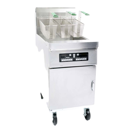
HDC, CFHDC, SCFHDC,
FPHDC, Y/KSCF/C/HC, BK1814
(High Efficiency Common Cabinet
Decathlon Fryers)
Dean, a member of the Commercial Food Equipment Service Association, recommends using
CFESA Certified Technicians.
APRIL 2011
*8196314*
24-Hour Service Hotline
PRINTED IN THE UNITED STATES
OF AMERICA
1-800-551-8633
Advertisement
Table of Contents
Troubleshooting

Related Manuals for Dean BK1814


Summary of Contents for Dean BK1814
- Page 1 HDC, CFHDC, SCFHDC, FPHDC, Y/KSCF/C/HC, BK1814 (High Efficiency Common Cabinet Decathlon Fryers) Dean, a member of the Commercial Food Equipment Service Association, recommends using CFESA Certified Technicians. APRIL 2011 *8196314* 24-Hour Service Hotline PRINTED IN THE UNITED STATES OF AMERICA...
- Page 2 Some food particles can spontaneously combust if left soaking in certain shortening material. Additional information can be obtained in the filtration The front ledge of the fryer is not a step. Do not stand on the fryer. Serious injury can result DANGER other cooking appliance.
- Page 3 Inhalation of carbon monoxide is known to the State of California to cause birth defects or other Do not bang fry baskets or other utensils on the fryer’s joiner strip. The strip is present to seal the joint between the fry vessels. Banging fry baskets on the strip to dislodge shortening will distort the strip, adversely affecting its fit.
-
Page 4: Table Of Contents
Cleaning the Gas Valve Vent Tube (if applicable)...1-9 Adjusting Burner Manifold Gas Pressure...1-9 Adjusting the Pilot Flame...1-10 Calibrating the Thermatron Controller and Backup Thermostat...1-10 Replacing Fryer Components...1-11 Troubleshooting and Problem Isolation...1-28 Troubleshooting Guides...1-36 1.10 Wiring Diagrams...1-37 1.11 Probe Resistance Charts...1-51 PARTS LIST…….…………………………………..………………………………... -
Page 6: Service Procedures
HIGH EFFICIENCY DECATHLON SERIES GAS FRYERS CHAPTER 1: SERVICE PROCEDURES 1.1 Functional Description High Efficiency Decathlon (HD) Series gas fryers contain a welded stainless steel frypot heated by gas flames diffused evenly through tubes built into the frypot. Flames originate from orifices in a burner manifold positioned beneath cast-steel burners. The burners are positioned in the tube openings at the front of the frypot. - Page 7 The pilot flame must be manually lit when the fryer is first placed into operation. A separate 24V circuit, activated by the fryer ON/OFF switch, provides voltage through the Thermatron to the gas valve main coil, which opens the main valve.
- Page 8 HD Series gas fryers may be equipped with Thermatron controls, Compu-Fry controllers, 3-Lane controllers or FAST controllers. In fryers equipped with Thermatron controls, the fryer is turned on and off by means of a rocker switch and the temperature is set by adjusting a potentiometer. An interface board is located in the component box (shield) behind the control panel (controller-equipped) or a Thermatron board is located in a component box inside the cabinet (Thermatron-equipped).
- Page 9 HIGH EFFICIENCY DECATHLON SERIES GAS FRYERS CHAPTER 1: SERVICE PROCEDURES Interface Boards (cont.) 106-3729 (24V): These boards are used in HD fryers equipped with Thermatron control systems. THERMATRON BOARD P/N 106-3729 Thermatron systems incorporate a temperature probe, a potentiometer, and a temperature control circuit board.
- Page 10 HIGH EFFICIENCY DECATHLON SERIES GAS FRYERS CHAPTER 1: SERVICE PROCEDURES Interface Boards (cont.) 826-2434: These interface boards are used in HD fryers equipped with electronic ignition and constant pilot. INTERFACE BOARD P/N 826-2434 Used on fryers equipped with electronic ignition and constant pilot.
- Page 11 Probe Resistance* * Disconnect 15-pin harness from controller before testing probe circuit. ** See Probe Resistance Chart at the end of this chapter. HIGH EFFICIENCY DECATHLON (HD) FRYER Indicates power from 12V transformer. Indicates power from 24V transformer. Indicates output (closed) from latch relay (K4).
-
Page 12: Accessing Fryers For Service
All HD Series gas fryers are equipped with a high-limit thermostat. In the event that the fryer fails to control the oil temperature, the high-limit thermostat prevents the fryer from overheating to flash point. - Page 13 When the fryer is leveled in its final position, install the restraints provided with the unit to limit its movement so that it does not depend on or transmit stress to the electrical conduit or connection.
-
Page 14: Cleaning The Gas Valve Vent Tube (If Applicable)
3. Insert the manometer fitting into the pressure tap hole. 4. Place the gas valve in the ON position then place the fryer power switch in the ON position. When the burner lights and continues to burn, check the gas pressure reading against the table on page 1-1. -
Page 15: Adjusting The Pilot Flame
2. Ensure the fryer ON/OFF switch is in the OFF position and light the pilot. 3. Place the fryer ON/OFF switch in the ON position. Set the potentiometer dial to 325°F (162°C). 4. Allow the oil to equalize at setpoint temperature. This is evident when the burners have cycled on and off several times. -
Page 16: Replacing Fryer Components
2. Unscrew the two controller panel screws. The controller panel is hinged at the bottom and will swing open from the top. 3. Unplug the fryer wiring harness and ground wire from the back of the controller. 4. Remove the controller by lifting it from the hinge slots in the fryer control panel frame. - Page 17 1. Disconnect the fryer from the electrical supply. 2. Drain cooking oil from the frypot. Allow the frypot to cool completely before proceeding. 3. Remove fryer door for easier access to the temperature probe. First, remove top hinge from bracket. Then, lift door off bottom hinge pin.
- Page 18 HIGH EFFICIENCY DECATHLON SERIES GAS FRYERS CHAPTER 1: SERVICE PROCEDURES 1.7.2 Replacing the Temperature Probe; Controller-equipped Fryers 6. Remove the burner shield by loosening the screw on each end. 7. Remove the burner rail by loosening the screw on each end. The burner rail secures the burners in the burner manifold.
- Page 19 HIGH EFFICIENCY DECATHLON SERIES GAS FRYERS CHAPTER 1: SERVICE PROCEDURES 1.7.2 Replacing the Temperature Probe; Controller-equipped Fryers 10. Locate the temperature probe inside the frypot. 11. The temperature probe can be removed through the bottom of the frypot as follows: Ensure the two-pin connector has been removed from the probe wiring harness (step 4, above).
- Page 20 2. Perform steps 1-4 in Section 1.7.1, Replacing the Controller. 3. Remove fryer door for easier access to the temperature probe. First, remove top hinge from bracket. Then, lift door off bottom hinge pin. 4. Remove two screws securing the high-limit mounting-bracket.
- Page 21 HIGH EFFICIENCY DECATHLON SERIES GAS FRYERS CHAPTER 1: SERVICE PROCEDURES 1.7.3 Replacing the High-limit Thermostat 6. Locate the high-limit probe inside the frypot. Carefully bend the outer tab at the rear of the high limit until the high limit can slid back and out of the retaining bracket.
- Page 22 1.7.3 Replacing the High-limit Thermostat 8. Mark and disconnect wires at the high-limit in the component box. 9. Remove high-limit from fryer by pulling the capillary tube and bulb through the component box opening (arrow). This may require removal of the control panel frame.
- Page 23 1. Disconnect the fryer from the electrical supply. 2. If switches are located in a control box within the fryer, remove the six screws securing the switch panel to the control box. Do not allow the switch panel to hang from the switch wiring harness or other wires.
- Page 24 1.7.5 Replacing the Gas Valve Drain the frypot or remove the handle from the drain valve before proceeding further. 1. Disconnect fryer from electrical and gas supplies. 2. Disconnect the wires from the gas valve terminal block, marking each wire to facilitate reconnections.
- Page 25 1.7.7 Replacing the Frypot 1. Open fryer doors and remove filter pan (if applicable). Ensure controller and all power switches are off. Drain and dispose of or store oil from all frypots prior to moving fryer. Hot cooking oil will cause severe burns. Never attempt to move this appliance when filled with hot cooking oil or to transfer hot cooking oil from one container to 2.
- Page 26 1.7.7 Replacing the Frypot 6. Remove the top cap. It is held in place by one screw on each side of the fryer. If the fryer has a controller on the front, the top cap may also be held in place by two screws on the front of each pot.
- Page 27 (Step 12). Use a screwdriver or similar tool to free flue cap from frypots. Remove flue cap by lifting up and off of fryer. Remove the screws (arrow) securing the flue cap to the frypot on the long edge.
- Page 28 13. Remove the clevis clip and oil return handle rod from the oil return valve at the rear of the fryer. Slip Section A of the clevis clip off of the oil return handle by pulling up on the rings.
- Page 29 Set aside for reassembly. 16. Remove the nipple attaching the oil return line to the bottom of the frypot at the rear of the fryer using a wrench. This may require removal of other pieces of the oil return manifold, as needed.
- Page 30 CHAPTER 1: SERVICE PROCEDURES 1.7.7 Replacing the Frypot 20. If the fryer is equipped with drain-valve microswitches, mark the wires and microswitch terminals, then disconnect wires from the switch. Secure the wires to prevent damage when frypot is removed. Left: Microswitch wires marked for removal (ensure microswitch terminals are marked the same as the wires removed).
- Page 31 HIGH EFFICIENCY DECATHLON SERIES GAS FRYERS CHAPTER 1: SERVICE PROCEDURES 1.7.7 Replacing the Frypot 23. Remove the temperature probe from frypot. (See Section 1.7.2, Replacing the Temperature Probe: Controller–equipped Fryers, for specific instructions.) 24. Remove the high-limit from the frypot (see Section 1.7.3, Replacing the High-limit Thermostat). 25.
- Page 32 1.7.7 Replacing the Frypot 27. Ensure wires and tubes will not be caught on the frypot when it is removed. 28. Remove frypot from fryer by lifting up and out. 29. Position the frypot upside down on a suitable work surface.
-
Page 33: Troubleshooting And Problem Isolation
Ignition failure occurs when the ignition module fails to sense a flame within the 60-second time delay period and locks out. Turn the fryer off, locate and fix the problem, then turn fryer back on to clear the module lock. - Page 34 The Electronic Circuits If gas and electrical power are supplied to the fryer, the next most likely cause of ignition failure is a problem in the 24 VAC circuit of fryers equipped with electronic ignition systems, or in the pilot system for those without electronic ignition.
- Page 35 If the fryer’s gas and air supplies are okay, the problem most likely is with one of the electrical components. Examine the ignition module for signs of melting, distortion, or discoloration due to excessive heat build-up in the fryer.
- Page 36 Flames "rolling" out of the fryer are usually an indication of negative pressure in the kitchen and make up air blowing down the flue. Air is being sucked out of the fryer enclosure and the flames are literally following the air. If negative pressure is not the cause, check for high burner-manifold gas pressure in accordance with the procedures in Section 1.4.
- Page 37 Common Controller Complaints. Most problems concerning controllers have to do with programming them. There are four common complaints. The complaints, their causes, and corrective actions are as follows for the Dean Compu-Fry controller: 1. Fryer constantly displays " Cause: Setpoint incorrect or missing. Corrective Action: Press then this to lock in the setpoint.
- Page 38 If the pump motor does not start, press the red reset switch located on the rear of the motor. Also, reset the filter circuit breaker located under the fryer control panel. If the pump then starts, something caused the motor to overheat. The pump most likely overheated for one of the following reasons: •...
- Page 39 HIGH EFFICIENCY DECATHLON SERIES GAS FRYERS CHAPTER 1: SERVICE PROCEDURES 1.8.5 Improper Filtration Function Incorrectly sized or installed paper will allow food particles and sediment to pass through and clog the suction tube on the bottom of the filter carriage. Particles large enough to block the suction tube may indicate that the crumb tray is not being used.
- Page 40 HIGH EFFICIENCY DECATHLON SERIES GAS FRYERS CHAPTER 1: SERVICE PROCEDURES 1.8.7 Improper Basket Lift Function Bell-Crank Basket Lifts Most High Efficiency Decathlon Series gas fryers are equipped with a bell-crank style basket lift. A cam and a bell crank are connected to the basket lift arm by a flat metal link.
-
Page 41: Troubleshooting Guides
B. ON/OFF switch is defective. Replace C. Thermostat(s) is/are defective. D. Go to "No burner flame" section. D. Inspect electronic sensor (while still in A. Inspect gas supply to fryer. Repair B. Allow unit to cycle on and off for A. Calibrate electronic/operating 1-36 CORRECTIVE ACTION switch. -
Page 42: Wiring Diagrams
HIGH EFFICIENCY DECATHLON SERIES GAS FRYERS CHAPTER 1: SERVICE PROCEDURES 1.10 Wiring Diagrams Note: The diagrams in this section depict wiring as of the date of manual publication. It may not reflect design changes made to the equipment after publication. Refer to the wiring diagram affixed to the unit when actually troubleshooting this equipment. - Page 43 HIGH EFFICIENCY DECATHLON SERIES GAS FRYERS CHAPTER 1: SERVICE PROCEDURES 1.10.2 Wingstreet Common Cabinet 1-38...
- Page 44 HIGH EFFICIENCY DECATHLON SERIES GAS FRYERS CHAPTER 1: SERVICE PROCEDURES 1.10.3 BK1814 Main Wiring Diagram prior after Sep. 2010 1-39...
- Page 45 HIGH EFFICIENCY DECATHLON SERIES GAS FRYERS CHAPTER 1: SERVICE PROCEDURES 1.10.4 BK1814 Main Wiring Diagram prior to Sep. 2010 1-40...
- Page 46 HIGH EFFICIENCY DECATHLON SERIES GAS FRYERS CHAPTER 1: SERVICE PROCEDURES 1.10.5 BK1814 RAM Wiring Diagram 1-41...
- Page 47 HIGH EFFICIENCY DECATHLON SERIES GAS FRYERS CHAPTER 1: SERVICE PROCEDURES 1.10.6 Filter Box 1-42...
- Page 48 HIGH EFFICIENCY DECATHLON SERIES GAS FRYERS CHAPTER 1: SERVICE PROCEDURES 1.10.7 Thermatron Controller 1-43...
- Page 49 HIGH EFFICIENCY DECATHLON SERIES GAS FRYERS CHAPTER 1: SERVICE PROCEDURES 1.10.8 FAST Controller prior to Feb 09 1-44...
- Page 50 HIGH EFFICIENCY DECATHLON SERIES GAS FRYERS CHAPTER 1: SERVICE PROCEDURES 1.10.9 FAST Controller Non-CE after Feb 09 1-45...
- Page 51 HIGH EFFICIENCY DECATHLON SERIES GAS FRYERS CHAPTER 1: SERVICE PROCEDURES 1.10.10 FAST Controller CE after Feb 09 1-46...
- Page 52 HIGH EFFICIENCY DECATHLON SERIES GAS FRYERS CHAPTER 1: SERVICE PROCEDURES 1.10.11 FAST Controller India 1-47...
- Page 53 HIGH EFFICIENCY DECATHLON SERIES GAS FRYERS CHAPTER 1: SERVICE PROCEDURES 1.10.12 KFC-1 Controller 1-48...
- Page 54 HIGH EFFICIENCY DECATHLON SERIES GAS FRYERS CHAPTER 1: SERVICE PROCEDURES 1.10.13 CM4S Controller 1-49...
- Page 55 HIGH EFFICIENCY DECATHLON SERIES GAS FRYERS CHAPTER 1: SERVICE PROCEDURES 1.10.14 Constant Pilot, FAST Ready 1-50...
-
Page 56: Probe Resistance Charts
HIGH EFFICIENCY DECATHLON SERIES GAS FRYERS CHAPTER 1: SERVICE PROCEDURES 1.11 Probe Resistance Charts Thermatron Probe Resistance Chart ° Celsius ° Fahrenheit Controller Probe Resistance Chart Ohms (±3%) ° Celsius ° Fahrenheit 108130 84606 66721 53020 42452 34206 27735 22641 18588 15349 12741... -
Page 57: Parts List
HIGH EFFICIENCY DECATHLON SERIES GAS FRYERS CHAPTER 2: PARTS LIST 2.1 High Efficiency Common Cabinet Decathlon (HDC) Primary Components 2.1.1 Decathlon HD50 Primary Components... - Page 58 Each section is labeled by size (e.g., D50) and parts are not interchangeable between different sized fryers. The parts in this manual are for use on Common Cabinet style fryer. If you have any questions, call the Frymaster and Dean 24-Hour Service Hotline, 1-800-551-8633.
- Page 59 HIGH EFFICIENCY DECATHLON SERIES GAS FRYERS 2.1.2 Decathlon HD60/63 Primary Components CHAPTER 2: PARTS LIST...
- Page 60 HIGH EFFICIENCY DECATHLON SERIES GAS FRYERS 2.1.2 Decathlon HD60/63 Primary Components ITEM PART # 106-9632 Frypot - S/S 106-9634 Frypot - S/S (Single HD60 without filtration) 823-5742SP Frypot - S/S (Single HD60 without filtration, Red Robin) 106-9638SP Frypot - S/S (Single HD63 without filtration) 823-6314 Frypot - S/S (Single HD63 without filtration, Red Robin) ►►►...
- Page 61 HIGH EFFICIENCY DECATHLON SERIES GAS FRYERS 2.1.2 Decathlon HD60/63 Primary Components ITEM PART # Basket Hanger 210-2737SP Single (60/63/65, 823-3649 with deflector) 210-6763 Single (Church's 63, 823-6524 with deflector) 823-7219 Single (Raising Cane's) 210-6761 Double (Church's 63, 823-6523 with deflector) 210-1482 Double (Chili's, 823-4999 with deflector) 823-7152...
- Page 62 HIGH EFFICIENCY DECATHLON SERIES GAS FRYERS CHAPTER 2: PARTS LIST 2.1.3 Decathlon HD/FPHD65 Primary Components...
- Page 63 HIGH EFFICIENCY DECATHLON SERIES GAS FRYERS 2.1.3 Decathlon HD/FPHD65 Primary Components ITEM PART # 106-9633 Frypot - S/S See Orifices, Section 2.2 ►►► See Additional Components and Controllers, Section 2.3 810-0705 Tube, Pilot Gas Supply, 810-0703 Tube, Pilot Gas Supply, 230-1431 Diffuser Assembly ►►►...
- Page 64 HIGH EFFICIENCY DECATHLON SERIES GAS FRYERS 2.1.3 Decathlon HD/FPHD65 Primary Components ITEM PART # 106-7710 Door Assembly, left or right 210-8077 Handle, Door 810-2346 Magnet, Door 230-4998 Hinge, Lower 823-5137 Hinge, Upper Right 823-5136 Hinge, Upper Left 823-5859 Basket Hanger, Church's (with Deflector) 823-5801 Basket Hanger, Chili’s Single System, 6"...
- Page 65 HIGH EFFICIENCY DECATHLON SERIES GAS FRYERS 2.1.4 Y/KSCF/C/HC Primary Components CHAPTER 2: PARTS LIST...
- Page 66 HIGH EFFICIENCY DECATHLON SERIES GAS FRYERS 2.1.4 Y/KSCF/C/HC Primary Components ITEM PART # 823-6138 Frypot – S/S (YSCFHC 14) 106-9637 Frypot – S/S (YSCFHC 18) 823-6367 Frypot – S/S (Y/KSCF/C/HC 18) India without hooks 823-7879 Frypot – S/S (Y/KSCF/C/HC 18) India with hooks ►►►...
- Page 67 HIGH EFFICIENCY DECATHLON SERIES GAS FRYERS CHAPTER 2: PARTS LIST 2.1.5 BK1814 Primary Components 2-11...
- Page 68 810-2280 Caster, Plate-mount 5" with Brake 106-7649 Cordset, 120V 10’ Power 807-5003 Receptacle, RAM 15A 125V 108-2582 Relay, Control Assy BK1814/HD50 includes 807-4114 and wire harness 812-2185SP Relay, Time Delay * Not illustrated. CHAPTER 2: PARTS LIST (cont.) DESCRIPTION ⁄...
-
Page 69: Orifices
HIGH EFFICIENCY DECATHLON SERIES GAS FRYERS 2.2 Orifices ITEM PART # Natural Orifices 810-2060 2.40 mm CE 810-3801 2.35 mm (China) 810-3132 2.20 mm 810-2938 0-1999 ft. 2.26mm 810-3053 2000-3999 ft. 2.18mm 810-3054 4000-5999 ft. 2.10mm 810-3055 6000-7999 ft. 2.04mm 810-3056 8000-8999 ft. -
Page 70: Additional Optional Components And Controllers
HIGH EFFICIENCY DECATHLON SERIES GAS FRYERS 2.3 Additional Components and Controllers ITEM PART # 826-2013 Thermostat, Sunne 810-2035 Knob, Thermostat 826-2117 Spark Module (module, 807-4383, and rajah connector, 807-4375) 106-7535SP Ignition Cable (for controller operated fryers) Pilot Assemblies 106-1839SP Natural Gas, Electronic Ignition with Controller includes ignition cable Non-CE 108-2787 Natural Gas, Electronic Ignition with Controller includes ignition cable CE 106-1238SP... - Page 71 Pump Relay 18 amp 24V coil 807-3574 Switch, Power (green lens) 807-3580 Switch, Rocker, Manual Filter Power 807-3579 Switch, Six-terminal Boil-out 807-3576 Switch, Fryer Reset (momentary) 807-3578 Switch, 3-position, ON-OFF-ON 807-3575 Switch, Blank Insert 807-3577 Circuit Breaker, 7 amp 807-4112...
-
Page 72: Drain Components
HIGH EFFICIENCY DECATHLON SERIES GAS FRYERS CHAPTER 2: PARTS LIST 2.4 Drain System Components 2.4.1 3" Drain Manifold Components 2-16... - Page 73 HIGH EFFICIENCY DECATHLON SERIES GAS FRYERS 2.4.1 3" Drain Manifold Components ITEM PART # 823-5188 Tube, 3" Filter Right, 50/60/80 823-7664 Tube, 3” Drain Middle BK50 of BK60/50/60 823-8167 Tube, 3” Drain YSCFHC318 823-4681 Tube, 3" Right Drain, 50/60/80 823-4682 Tube, 3"...
- Page 74 HIGH EFFICIENCY DECATHLON SERIES GAS FRYERS CHAPTER 2: PARTS LIST 2.4.2 Drain Valve Assemblies 2-18...
-
Page 75: Drain Valve Assemblies
Valve Assy, 1 ½” Drain 106-8401 Valve Assy, 1 ½” Drain 106-3977 Valve Assy, 1 ½” Drain BK60/50/60, Right 60 on BK1814- BK60/50/RAM/60 and BK60/RAM/50/60 108-0448 Valve Assy, 1 ½” Drain 810-2784 Valve, 1 ¼” Full Port Drain(includes item # - O-ring) 823-5075 Valve , 1 ¼”... -
Page 76: Oil Return System
HIGH EFFICIENCY DECATHLON SERIES GAS FRYERS 2.5 Oil Return System CHAPTER 2: PARTS LIST 2-20... - Page 77 HIGH EFFICIENCY DECATHLON SERIES GAS FRYERS 2.5 Oil Return System ITEM PART # 106-4006SP Valve Assembly, ½" Oil Return (see Section 2.6 for components) 106-7598SP Valve, Solenoid with Female Pins 200-9295 Handle, Oil Return (YSCFC 14, SCFHDC 50/60, HD 65) 200-8929 Handle, Oil Return (YSCFC 18) 809-0601...
-
Page 78: Additional Oil Return Components
HIGH EFFICIENCY DECATHLON SERIES GAS FRYERS CHAPTER 2: PARTS LIST 2.6 Additional Oil Return Components 2-22... - Page 79 816-0093 Gasket (Pump/Motor) (included with motor) Motor and Gasket Kit 826-1785 100V 50/60Hz 826-1712 115V 50/60Hz 200-8929 Handle, Oil Return (use 200-9295 BK1814) 809-0601 Clip, Clevis, Rod End 816-0638 Cap, Vinyl Yellow 816-0637 Cap, Vinyl Blue 816-0639 Cap, Vinyl Red...
-
Page 80: Oil Disposal (Popeye's)
HIGH EFFICIENCY DECATHLON SERIES GAS FRYERS 2.7 Oil Disposal Plumbing (Popeye's) ITEM PART # 108-1121 Valve, Oil Disposal 810-0278 Valve 900-5953 Handle 814-0047 Sleeve 108-1117 Oil Disposal Assembly 810-2379 Hose, 107.5", ½" x ½" 813-0699 Nipple, Snaptite, ½" 823-7153 Handle 816-0631 Sleeve/Cap, Handle 810-0487... -
Page 81: Oil Return Wand
HIGH EFFICIENCY DECATHLON SERIES GAS FRYERS 2.8 Oil Return Wand ITEM PART # 106-3997 Wand Valve Assembly 810-0278 Valve, ½" Ball 806-9128 Bracket, Microswitch 816-0220 Insulation, Microswitch 807-2103 Microswitch, CE Micro-roller, Straight Lever 900-2849 Cover, Microswitch 900-2839 Handle, Wand Valve 813-0022 Nipple, ½"... -
Page 82: Over-The-Top Oil Return System
HIGH EFFICIENCY DECATHLON SERIES GAS FRYERS 2.9 Over-the-Top Oil Return System ITEM PART # 810-1669 Adapter, Female ⅞" O.D. x ½" 810-1680 Flexline, ⅝" I.D. x 6.50" Long 810-2513 Tubing, Faucet Upper 810-2699 Coupling, Quick Disconnect, Snaptite 810-2700 Nipple, Quick Disconnect, Snaptite 810-3234 Tubing, Faucet Rear 813-0093... -
Page 83: Filtration Components
HIGH EFFICIENCY DECATHLON SERIES GAS FRYERS 2.10 Filtration Components 2.10.1 Filtration Components; SCFHDC50 Series and BK1814 Fryers ITEM PART # 823-6366 Basket, Crumb 823-7425 Basket, Crumb (BK1814) 810-3541 Ring, Hold-down 200-8003 Screen, Sana Grid 823-7294 Pan, Filter 813-0568 Plug, ⅛" NPT Socket-Head Pipe 810-2805 Caster, 2"... - Page 84 HIGH EFFICIENCY DECATHLON SERIES GAS FRYERS 2.10.2 Filtration Components; SCFHDC60 Series Fryers ITEM PART # 823-6018 Basket, Crumb 823-7110 Basket, Crumb (Raising Cane's) 810-3540 Ring, Hold-down 200-5726 Screen, Sana Grid 823-6338 Pan, Filter 810-2805 Caster, 2" Filter Pan 809-0070 Nut, ¼-20 Hex, S/S 823-6403 Lid (mounted in frame) * Not illustrated.
- Page 85 HIGH EFFICIENCY DECATHLON SERIES GAS FRYERS 2.10.3 Filtration Components; Y/K/SCF/C/HC218 and 63 Series Fryers ITEM PART # 823-6172 Basket, Crumb 810-3195 Ring, Hold-down 106-7330SP Screen Assembly, Filter 823-7534 Pan, Filter 813-0568 Plug, ⅛" NPT, Socket-Head 810-2805 Caster, 2" Filter Pan 809-0823 Nut, Nylock, ¼-20 823-6507...
- Page 86 HIGH EFFICIENCY DECATHLON SERIES GAS FRYERS 2.10.4 Filtration Components; Y/KSCF/C/HC218 Export (India) Series Fryers prior to May 2010 ITEM PART # 823-5427 Basket, Crumb 823-4470 Ring, Hold-down 823-4471 Handle Hold Down Ring 106-7912SP Screen Assembly, Filter 108-1022SP Pan, Filter 813-0679 Plug, ⅛"...
- Page 87 HIGH EFFICIENCY DECATHLON SERIES GAS FRYERS 2.10.5 Filtration Components; Y/KSCF/C/HC218 Export (India) Series Fryers after May 2010 ITEM PART # 823-7904 Basket, Crumb 810-3195 Ring, Hold-down 823-7834 106-7330SP Screen Assembly, Filter 823-7534 Pan, Filter 813-0568 Plug, ⅛" SS NPT, Sq-Head 810-2805 Caster, 2"...
- Page 88 HIGH EFFICIENCY DECATHLON SERIES GAS FRYERS 2.10.6 Filtration Components; 65 Series Fryers (Filter Paper Option) ITEM PART # 823-6018 Basket, Crumb 810-3540 Ring, Hold-down 200-5726 Screen, Sana Grid 813-0568 Plug, ⅛" NPT, Socket-Head Pipe 823-6304 Pan, Filter 810-2805 Caster, 2" Filter Pan 809-0823 Nut, Nylock, ¼-20 823-5857...
- Page 89 HIGH EFFICIENCY DECATHLON SERIES GAS FRYERS 2.10.7 Filtration Components; 65 Series Fryers (Filter Leaf Option) ITEM PART # 823-5851 Basket, Crumb 106-6466SP Filter Leaf with Suction Tube Assembly 106-8399 Filter Leaf (screen only) 823-5258SP Filter Pan 810-2805 Caster, 2" 809-0070 Nut, ¼"-20 Hex 823-5857 Lid (mounted in frame)
-
Page 90: Basket Lift Components
HIGH EFFICIENCY DECATHLON SERIES GAS FRYERS CHAPTER 2: PARTS LIST 2.11 Basket Lift Components 2-34... - Page 91 HIGH EFFICIENCY DECATHLON SERIES GAS FRYERS 2.11 Basket Lift Components ITEM PART # HDC50 Models (106-7702) 823-3625 Lift Rod 813-0035 Bushing, Bronze 200-2069 Lift Bar 210-2140 Bushing, ⅜" x ½" 824-1783 Back, Upper 824-0991 Back, Lower 823-6871 Lift Assembly, Left 823-6870 Lift Assembly, Right 106-8370...
-
Page 92: Accessories
HIGH EFFICIENCY DECATHLON SERIES GAS FRYERS CHAPTER 2: PARTS LIST 2.12 Accessories 2-36... -
Page 93: Fasteners (Screws, Nuts, Bolts)
Drain Nipple, extension 1 ½" 803-0278 L-shaped Brush 803-0277 Grid Assembly 810-2552 Mesh grid assembly 810-2235 Grid assembly, rack 803-0197 Fryer’s Friend 803-0304 Basket, Twin (KFC) 803-0392 Basket, Twin (Raising Cane's) 803-0271 Basket, Twin 803-0099 Basket, Full 803-0337 Basket, 6" x 8 ¾" x 16 ¾"... -
Page 94: Flexlines
HIGH EFFICIENCY DECATHLON SERIES GAS FRYERS 2.14 Flexlines LENGTH 3.0-inch 4.5-inch 5.0-inch 6.5-inch 8.5-inch 9.5-inch 11.5-inch Flexlines come with a ⅞-inch female fitting on each end. Adapters (listed below) are required to fit them to standard ½- inch NPT pipe nipples of fittings. Add ¾-inch to the overall length of the flexline for each adapter used. NOTE: Be aware that these are flexible metal lines. -
Page 95: Appendix: Pre-Common Cabinet Hd65 Parts List
HIGH EFFICIENCY DECATHLON SERIES GAS FRYERS Appendix: Pre-Common Cabinet HD65 Parts List ITEM PART # 823-5243 Frypot - S/S 810-2072 Gas Manifold (weld assembly) 810-2032 Pilot Burner, Natural/G20/25 Gas (primary and trailing) 810-2155 Pilot Burner, LP/G31 Gas (primary and trailing) 812-1674 Pilot Burner, Mod. - Page 96 HIGH EFFICIENCY DECATHLON SERIES GAS FRYERS Appendix: Pre-Common Cabinet HD65 Parts List ITEM PART # Top Cap 824-1781 x1 (for single) 823-6010 x2 (for 2-battery) 823-6011 x4 (for 4-battery) 823-6090 x3 (for 5-battery) 823-5975 x2 (for 5- and 6-battery) 823-5976 x4 (for 6-battery) 824-1656 x3, with work shelf...
- Page 97 THIS PAGE INTENTIONALLY LEFT BLANK...
- Page 98 Dean, 8700 Line Avenue, 8700 Line Avenue, Shreveport, Louisiana 71106 TEL 1-318-865-1711 FAX (Parts) 1-318-688-2200 FAX (Tech Support) 1-318-219-7135 SERVICE HOTLINE PRINTED IN THE UNITED STATES 1-800-551-8633 819-6314 APR 2011...