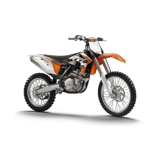
KTM 450 SX-F EU Owner's Manual
Hide thumbs
Also See for 450 SX-F EU:
- Owner's manual (98 pages) ,
- Owner's manual (107 pages) ,
- Repair manual (245 pages)
Table of Contents
Advertisement
Quick Links
Advertisement
Table of Contents

Related Manuals for KTM 450 SX-F EU


Summary of Contents for KTM 450 SX-F EU
- Page 1 OWNER'S MANUAL 2012 450 SX‑F EU 450 SX‑F USA Art. no. 3211717en...
- Page 3 KTM accepts no liability for delivery options, deviations from illustrations and descriptions, as well as misprints and other errors.
-
Page 4: Table Of Contents
TABLE OF CONTENTS Adjusting the rebound damping of the fork....... 28 TABLE OF CONTENTS MEANS OF REPRESENTATION ..........4 Handlebar position ............28 IMPORTANT INFORMATION ..........5 Adjusting handlebar position ........29 VIEW OF VEHICLE............... 7 Activating the Factory Start (450 SX‑F USA) ....29 View of the vehicle from the left front (example) .... - Page 5 TABLE OF CONTENTS 450 SX‑F USA .............. 85 Changing the front brake linings ......... 51 Checking the free travel of the foot brake lever ....53 TECHNICAL DATA - TIGHTENING TORQUES FOR CHASSIS ................87 Adjusting the basic position of the foot brake lever ..
-
Page 6: Means Of Representation
All work marked with this symbol requires specialist knowledge and technical understanding. In the interest of your own safety, have these jobs done in an authorized KTM workshop! There, your motorcycle will be serviced optimally by specially trained experts using the specialist tools required. -
Page 7: Important Information
Warranty The work prescribed in the service schedule must be carried out by an authorized KTM workshop only and confirmed in the customer's service record and in the KTM dealer.net; otherwise, all warranty claims will be void. No warranty claim can be honored for damage resulting from manipulation and/or other changes to the vehicle. - Page 8 IMPORTANT INFORMATION Environment Motorcycling is a wonderful sport and we naturally hope that you can enjoy it to the full. However, it is a potential problem for the environment and can lead to conflicts with other persons. But if you use your motorcycle responsibly, you can ensure that such prob- lems and conflicts do not have to occur.
-
Page 9: View Of Vehicle
VIEW OF VEHICLE View of the vehicle from the left front (example) 800180-10 Hand brake lever ( p. 10) Clutch lever ( p. 10) Filler cap Air filter box lid Fuel tap ( p. 12) Choke ( p. 12) Chain guide Shift lever ( p. -
Page 10: View Of The Vehicle From The Right Rear (Example)
VIEW OF VEHICLE View of the vehicle from the right rear (example) 800183-10 Short circuit button ( p. 10) Electric starter button ( p. 11) Fork compression adjustment Fork rebound adjustment Level viewer, engine oil Foot brake lever ( p. 13) Level viewer for brake fluid, rear Shock absorber rebound adjustment Shock absorber compression adjustment... -
Page 11: Serial Numbers
SERIAL NUMBERS Chassis number The chassis number is stamped on the steering head on the right. B00262-10 Type label The type label is fixed to the front of the steering head. B00262-20 Engine number The engine number is stamped on the left side of the engine under the engine ... -
Page 12: Controls
CONTROLS Clutch lever The clutch lever is fitted on the left side of the handlebar. The clutch is hydraulically operated and self-adjusting. B00406-10 Hot start lever The hot start lever is fitted on the left side of the handlebar. ... -
Page 13: Electric Starter Button
CONTROLS Electric starter button Electric starter button is fitted on the right side of the handlebar. Possible states • Electric starter button in basic position pressed – In this position, the electric starter is actuated. • Electric starter button 400198-10 Opening filler cap Danger... -
Page 14: Factory Start (450 Sx-F Usa)
CONTROLS Factory Start (450 SX‑F USA) The Factory Start is mounted on the right fork protector. Possible states Factory Start is deactivated – The fork is in the normal operating mode. • Factory Start is activated – The fork is compressed and the front of the motor- •... -
Page 15: Shift Lever
CONTROLS Shift lever 5.12 Shift lever is mounted on the left side of the engine. B00426-11 The gear positions can be seen in the photograph. The neutral or idle position is between the first and second gears. B00426-10 Foot brake lever 5.13 Foot brake lever is located in front of the right footrest. -
Page 16: Preparing For Use
When using your motorcycle, remember that others may feel disturbed by excessive noise. – Make sure that the pre-delivery inspection work has been carried out by an authorized KTM workshop. You receive a delivery certificate and the service record at vehicle handover. -
Page 17: Running-In The Engine
Rides at low temperatures or in snow. ( p. 17) Preparing for rides on dry sand – Fit a dust protection device on the air filter. Dust protection device for air filter (77206920000) Info See the KTM PowerParts fitting instructions. B00435-01... -
Page 18: Preparing For Rides On Wet Sand
Sand protection device for air filter (77206922000) Info See the KTM PowerParts fitting instructions. – Adjust the carburetor jetting and settings. Info B00436-01 Your authorized KTM workshop has the recommended carburetor tuning settings. – Clean the chain. Chain cleaner ( p. 90) –... -
Page 19: Preparing For Rides At High Temperatures And Low Speeds
Fit a waterproofing device on the air filter. Waterproofing device for air filter (77206921000) Info See the KTM PowerParts fitting instructions. – Adjust the carburetor jetting and settings. Info B00437-01 Your authorized KTM workshop has the recommended carburetor tuning settings. -
Page 20: Riding Instructions
RIDING INSTRUCTIONS Checks and maintenance before putting into operation Info Before every trip, check the condition of the vehicle and ensure that it is safe to operate. The vehicle must be in perfect technical condition when used. – Check the engine oil level. ( p. -
Page 21: Starting Up
Do not change into a low gear at high engine speed. The engine races and the rear wheel can lock up. Info If you hear unusual noises while riding, stop immediately, switch off the engine and contact an authorized KTM workshop. First gear is used for starting off or for steep inclines. -
Page 22: Stopping, Parking
RIDING INSTRUCTIONS Stopping, parking Warning Risk of misappropriation Usage by unauthorized persons. – Never leave the vehicle while the engine is running. Secure the vehicle against use by unauthorized persons. Warning Danger of burns Some vehicle components become very hot when the vehicle is operated. –... -
Page 23: Service Schedule
• • Make the service entry in KTM DEALER.NET and in the service record. S1N: Once after 1 service hour - corresponds to about 7 liters of fuel (1.8 US gal) S10A: Every 10 service hours - corresponds to about 70 liters of fuel (18.5 US gal) / after every race S20A: Every 20 service hours - corresponds to about 140 liters of fuel (37 US gal) S30A: Every 30 service hours - corresponds to about 210 liters of fuel (55.5 US gal) -
Page 24: Service Work (As Additional Order)
SERVICE SCHEDULE Service work (as additional order) S20N S20A S40A S80A • Change the front brake fluid. Change the rear brake fluid. • Change the hydraulic clutch fluid. p. 48) • Grease the steering head bearing. p. 35) • Check/set the carburetor components. •... -
Page 25: Tuning The Chassis
Caution Danger of accidents Disassembly of pressurized parts can lead to injury. – The shock absorber is filled with high density nitrogen. Adhere to the description provided. (Your authorized KTM workshop will be glad to help.) Info The low-speed setting can be seen during the slow to normal compression of the shock absorber. -
Page 26: Adjusting The High-Speed Compression Damping Of The Shock Absorber
Caution Danger of accidents Disassembly of pressurized parts can lead to injury. – The shock absorber is filled with high density nitrogen. Adhere to the description provided. (Your authorized KTM workshop will be glad to help.) Info The high-speed setting can be seen during the fast compression of the shock absorber. -
Page 27: Measuring Rear Wheel Sag Unloaded
TUNING THE CHASSIS – Turn adjusting screw clockwise up to the last perceptible click. – Turn back counterclockwise by the number of clicks corresponding to the shock absorber type. Guideline Rebound damping (450 SX‑F EU) Comfort 17 clicks Standard 15 clicks Sport 13 clicks... -
Page 28: Checking The Riding Sag Of The Shock Absorber
Caution Danger of accidents Disassembly of pressurized parts can lead to injury. – The shock absorber is filled with high density nitrogen. Adhere to the description provided. (Your authorized KTM workshop will be glad to help.) Info Before changing the spring preload, make a note of the present setting, e.g., by measuring the length of the spring. -
Page 29: Adjusting The Riding Sag
TUNING THE CHASSIS Adjusting the riding sag 9.10 – Remove the shock absorber. p. 36) – After removing the shock absorber, clean it thoroughly. – Choose and mount a suitable spring. Guideline Spring rate (450 SX‑F EU) Weight of rider: 65… 75 kg (143… 54 N/mm (308 lb/in) 165 lb.) Weight of rider: 75…... -
Page 30: Adjusting The Rebound Damping Of The Fork
TUNING THE CHASSIS Guideline Compression damping (450 SX‑F EU) Comfort 14 clicks Standard 12 clicks Sport 10 clicks Compression damping (450 SX‑F USA) Comfort 14 clicks Standard 12 clicks Sport 10 clicks Info Turn clockwise to increase damping; turn counterclockwise to reduce damp- ing. -
Page 31: Adjusting Handlebar Position
TUNING THE CHASSIS Adjusting handlebar position 9.15 – Remove the four screws . Remove the handlebar clamp. Remove the handlebar and lay it to one side. 0 0 1 Info 0 0 2 0 0 2 Protect the motorcycle and its attachments from damage by covering them. Do not bend the cables and lines. -
Page 32: Service Work On The Chassis
SERVICE WORK ON THE CHASSIS Raising the motorcycle with the lift stand 10.1 Note Danger of damage The parked vehicle may roll away or fall over. – Always place the vehicle on a firm and even surface. – Raise the motorcycle at the frame underneath the engine. Lift stand (54829055000) The wheels should no longer touch the ground. -
Page 33: Loosening The Fork Protector
SERVICE WORK ON THE CHASSIS – Press the dust boots back into their normal position. – Remove excess oil. – Position the fork protection. ( p. 31) – Remove the motorcycle from the lift stand. ( p. 30) Loosening the fork protector 10.5 –... -
Page 34: Installing The Fork Legs
SERVICE WORK ON THE CHASSIS Installing the fork legs 10.8 – Position the fork legs. Info The upper milled groove in the fork leg must be flush with the top edge of the upper triple clamp. Position bleeder screws toward the front. ... -
Page 35: Removing The Lower Triple Clamp
SERVICE WORK ON THE CHASSIS Removing the lower triple clamp 10.11 – Remove the fork legs. p. 31) – Dismount the start number plate ( p. 36) – Remove the front fender. ( p. 36) – Remove the handlebar cushion. –... - Page 36 SERVICE WORK ON THE CHASSIS – Position the fork legs. Info The upper milled groove in the fork leg must be flush with the top edge of the upper triple clamp. Position bleeder screws toward the front. B00407-10 – Fully tighten screws ...
-
Page 37: Checking The Steering Head Bearing Play
Danger of accidents Unstable vehicle handling from incorrect steering head bearing play. – Adjust the steering head bearing play without delay. (Your authorized KTM workshop will be glad to help.) Info If the bike is ridden with play in the steering head bearing, the bearing and the bearing seats in the frame can become dam- aged over time. -
Page 38: Dismount The Start Number Plate
SERVICE WORK ON THE CHASSIS Dismount the start number plate 10.16 – Remove screw and take off clamp. – Remove screw . Remove the start number plate. 101278-10 Installing the start number plate 10.17 – Position the start number plate. Mount and tighten screw ... -
Page 39: Installing The Shock Absorber
SERVICE WORK ON THE CHASSIS – Press angle lever toward the rear. – Press linkage lever downward. B00268-10 – Detach springs Spring hooks (50305017000) – Remove screw B00409-10 – Remove screw – Turn the shock absorber toward the rear and remove the exhaust manifold. –... -
Page 40: Removing The Seat
SERVICE WORK ON THE CHASSIS – Remove the motorcycle from the lift stand. ( p. 30) Removing the seat 10.22 – Remove screw – Lift up the seat at the rear, pull it back and then remove it from above. 101279-10 Mounting the seat 10.23... -
Page 41: Installing The Air Filter
SERVICE WORK ON THE CHASSIS – Remove the air filter box lid. ( p. 38) – Detach air filter holder at the bottom and swing it to one side. Remove the air filter with the air filter support. – Remove the air filter from the air filter support. -
Page 42: Removing Main Silencer
SERVICE WORK ON THE CHASSIS Removing main silencer 10.29 Warning Danger of burns The exhaust system gets very hot when the vehicle is driven. – Allow the exhaust system to cool down. Do not touch hot components. – Disconnect spring –... -
Page 43: Removing The Fuel Tank
SERVICE WORK ON THE CHASSIS Removing the fuel tank 10.32 Danger Fire hazard Fuel is highly flammable. – Never refuel the vehicle near open flames or burning cigarettes, and always switch off the engine first. Be careful that no fuel is spilt, especially on hot vehicle components. Clean up spilt fuel immediately. –... -
Page 44: Checking For Chain Dirt Accumulation
SERVICE WORK ON THE CHASSIS – Check the throttle cable routing. ( p. 46) – Position the fuel tank and fit the two spoilers to the sides of the radiator bracket. – Make sure that no cables are trapped or damaged. B00414-01 –... -
Page 45: Checking The Chain Tension
SERVICE WORK ON THE CHASSIS – Clean the chain regularly and then treat with chain spray. Chain cleaner ( p. 90) Off-road chain spray ( p. 90) 400725-01 Checking the chain tension 10.36 Warning Danger of accidents Danger caused by incorrect chain tension. –... -
Page 46: Checking The Chain, Rear Sprocket, Engine Sprocket And Chain Guide
SERVICE WORK ON THE CHASSIS – Loosen nut – Loosen nuts – Adjust the chain tension by turning the adjusting screws left and right. Guideline Chain tension 55… 58 mm (2.17… 2.28 in) Turn adjusting screws on the left and right so that the markings on the left ... - Page 47 SERVICE WORK ON THE CHASSIS – Check the chain sliding guard for wear. » If the bottom edge of the chain bolt is in line with or below the chain sliding guard: – Change the chain sliding guard. – Check that the chain sliding guard is firmly seated. »...
-
Page 48: Adjusting The Chain Guide
If the frame exhibits cracking or deformation due to a mechanical impact: – Change the frame. Info A frame that has been damaged due to a mechanical impact must always be changed. Repair of the frame is not authorized by KTM. 800188-10 Checking the swingarm 10.41 –... -
Page 49: Checking The Rubber Grip
SERVICE WORK ON THE CHASSIS Checking the rubber grip 10.43 – Check the rubber grips on the handlebar for damage and wear and to ensure they are firmly seated. » If a rubber grip is damaged, worn or loose: – Change and secure the rubber grip. -
Page 50: Changing The Hydraulic Clutch Fluid
SERVICE WORK ON THE CHASSIS Changing the hydraulic clutch fluid 10.47 Warning Environmental hazard Hazardous substances cause environmental damage. – Oil, grease, filters, fuel, cleaners, brake fluid, etc., should be disposed of as stipulated in applicable regulations. – Move the clutch fluid reservoir mounted on the handlebar to a horizontal position. –... -
Page 51: Brakes
Danger of accidents Reduced braking efficiency due to worn brake disc(s). – Change the worn brake disc(s) without delay. (Your authorized KTM workshop will be glad to help.) – Check the thickness of the front and rear brake discs at several places on the disk to see if it conforms to measurement ... -
Page 52: Checking The Brake Fluid Level Of The Front Brake
Warning Danger of accidents Reduced braking effect caused by old brake fluid. – Change the brake fluid of the front and rear brake according to the service schedule. (Your authorized KTM workshop will be glad to help.) – Move the brake fluid reservoir mounted on the handlebar to a horizontal position. -
Page 53: Checking The Front Brake Linings
Warning Danger of accidents Reduced braking effect caused by old brake fluid. – Change the brake fluid of the front and rear brake according to the service schedule. (Your authorized KTM workshop will be glad to help.) Warning Danger of accidents Reduced braking efficiency due to oil or grease on the brake discs. - Page 54 Brake linings available from accessory suppliers are often not tested and approved for use on KTM vehicles. The construc- tion and friction factor of the brake linings and therefore the brake power can differ considerably from the original KTM brake linings. If brake linings are used that differ from the originals, there is no guarantee that they comply with the origi- nal license.
-
Page 55: Checking The Free Travel Of The Foot Brake Lever
BRAKES – Correct the brake fluid quantity to level Guideline Dimension (brake fluid level below 5 mm (0.2 in) top edge of container) Brake fluid DOT 4 / DOT 5.1 ( p. 88) – Position cover with membrane ... -
Page 56: Chassis
Warning Danger of accidents Reduced braking effect caused by old brake fluid. – Change the brake fluid of the front and rear brake according to the service schedule. (Your authorized KTM workshop will be glad to help.) – Stand the vehicle upright. -
Page 57: Checking Rear Brake Linings
Warning Danger of accidents Reduced braking effect caused by old brake fluid. – Change the brake fluid of the front and rear brake according to the service schedule. (Your authorized KTM workshop will be glad to help.) Warning Environmental hazard Hazardous substances cause environmental damage. - Page 58 BRAKES – Press the brake caliper toward the brake disc to push back the brake piston and ensure that no brake fluid runs out of the brake fluid reservoir, sucking it off if it does. Info Make sure when pushing back the brake piston that you do not press the brake caliper against the spokes.
-
Page 59: Wheels, Tires
WHEELS, TIRES Removing front wheel 12.1 – Raise the motorcycle with the lift stand. ( p. 30) – Press the brake caliper by hand on to the brake disc in order to press back the brake pistons. Info Make sure when pushing back the brake pistons that you do not press the brake caliper against the spokes. -
Page 60: Removing The Rear Wheel
WHEELS, TIRES – Lift the front wheel into the fork, position it, and insert the wheel spindle. – Mount and tighten screw Guideline Screw, front wheel spindle M24x1.5 45 Nm (33.2 lbf ft) – Activate the hand brake lever multiple times until the brake linings are in contact with the brake disc. -
Page 61: Checking The Tire Condition
12.5 Info Only mount tires approved and/or recommended by KTM. Other tires could have a negative effect on riding behavior. The type, condition and air pressure of the tires all have an important impact on the riding behavior of the motorcycle. -
Page 62: Checking Tire Air Pressure
Danger of accidents Instable handling due to incorrect spoke tension. – Ensure that the spoke tension is correct. (Your authorized KTM workshop will be glad to help.) Info A loose spoke can cause wheel imbalance, which leads to more loose spokes in a short time. -
Page 63: Electrical System
– Do not discard batteries with the household trash. Dispose of a defective battery in an environmentally compatible manner. Give the battery to your KTM dealer or to a recycling center that accepts used batteries. Warning Environmental hazard Hazardous substances cause environmental damage. -
Page 64: Removing The Main Fuse
ELECTRICAL SYSTEM Info Even when there is no load on the battery, it still loses power steadily. The charge state and the type of charge are very important for the service life of the battery. Rapid recharging with a high charging current shortens the battery's service life. If the charging current, charging voltage and charging time are exceeded, electrolyte escapes through the safety valves. -
Page 65: Installing The Main Fuse
ELECTRICAL SYSTEM Installing the main fuse 13.5 Warning Fire hazard The electrical system can be overloaded if the wrong fuses are used. – Use only fuses with the prescribed amperage. Never by-pass or repair fuses. – Insert the main fuse. Fuse (58011109110) ( p. -
Page 66: Cooling System
COOLING SYSTEM Cooling system 14.1 Water pump in the engine circulates the coolant. The pressure resulting from the warming of the cooling system is regulated by a valve in radiator cap . This ensures that operating the vehicle at the specified coolant tem- ... -
Page 67: Draining The Coolant
COOLING SYSTEM Condition The engine is cold. – Stand the motorcycle upright on a horizontal surface. – Remove radiator cap. – Check the coolant level in the radiator. Coolant level above the radiator fins. 10 mm (0.39 in) » If the coolant level does not meet specifications: –... - Page 68 COOLING SYSTEM – Refit the radiator cap. – Make a short test ride. – Check the coolant level. ( p. 64)
-
Page 69: Tuning The Engine
TUNING THE ENGINE Checking the play in the throttle cable 15.1 – Check the throttle grip for smooth operation. – Move the handlebar to the straight-ahead position. Move the throttle grip back- wards and forwards to ascertain the play in the throttle cable. Play in throttle cable 3…... -
Page 70: Carburetor - Adjusting Idle
TUNING THE ENGINE Carburetor - adjusting idle 15.4 – Screw in idle adjusting screw until it stops and then to the prescribed basic set- ting. Guideline Idle mixture adjusting screw Open 1.5 turns Adjustment tool for mixture control screw (77329034000) –... -
Page 71: Ignition Curve Plug Connection
TUNING THE ENGINE Warning Environmental hazard Improper handling of fuel is a danger to the environment. – Do not allow fuel to get into the ground water, the ground, or the sewage system. Info Carry out this work with a cold engine. –... -
Page 72: Adjusting The Basic Position Of The Shift Lever
TUNING THE ENGINE Adjusting the basic position of the shift lever 15.9 – Remove screw and take off shift lever B00427-10 – Clean gear teeth of the shift lever and shift shaft. – Mount the shift lever on the shift shaft in the required position and engage the gearing. -
Page 73: Service Work On The Engine
SERVICE WORK ON THE ENGINE Checking engine oil level 16.1 Info The engine oil level can be checked when the engine is cold or warm. – Stand the motorcycle upright on a horizontal surface. Condition Engine is cold. – Check the engine oil level. The engine oil level is up to the bottom edge of the level viewer. - Page 74 SERVICE WORK ON THE ENGINE – Mount and tighten oil drain plug with the seal ring. Guideline Oil drain plug with magnet M12x1.5 20 Nm (14.8 lbf ft) 800011-10 – Remove screws . Remove the oil filter cover with the O-ring. ...
-
Page 75: Adding Engine Oil
SERVICE WORK ON THE ENGINE Adding engine oil 16.3 Info Too little engine oil or poor-quality engine oil results in premature wear to the engine. – Remove the oil filler plug on the clutch cover and fill up with engine oil. ... -
Page 76: Cleaning, Care
CLEANING, CARE Cleaning motorcycle 17.1 Note Material damage Damage and destruction of components by high-pressure cleaning equipment. – Never clean the vehicle with high-pressure cleaning equipment or a strong water-jet. The excessive pressure can penetrate electri- cal components, socket connects, throttle cables, and bearings, etc., and can damage or destroy these parts. Warning Environmental hazard Hazardous substances cause environmental damage. -
Page 77: Storage
– Place the vehicle on a dry storage place that is not subject to large temperature variations. Info KTM recommends raising the motorcycle. – Raise the motorcycle with the lift stand. ( p. 30) – Cover the vehicle with an air-permeable cover or blanket. -
Page 78: Troubleshooting
TROUBLESHOOTING Faults Possible cause Action – The engine cannot be cranked (elec- Operating error Carry out the start procedure. ( p. 18) tric starter) – Battery discharged Recharge the battery. p. 61) – Check the charging voltage. – Check the closed current. –... - Page 79 TROUBLESHOOTING Faults Possible cause Action – Engine stalls or pops back into the The intake system has an air leak Check rubber sleeves and carburetor for tight- carburetor ness. – Engine overheats Too little coolant in cooling system Check the cooling system for leakage. –...
-
Page 80: Technical Data - Engine
TECHNICAL DATA - ENGINE Design 1-cylinder 4-stroke engine, water-cooled Displacement 449.3 cm³ (27.418 cu in) Stroke 60.8 mm (2.394 in) Bore 97 mm (3.82 in) Compression ratio 12.5:1 Idle speed 1,550… 1,650 rpm Control DOHC, four valves controlled via cam lever, drive via helical gear pair and tooth-wheel chain Valve diameter, intake 40.4 mm (1.591 in) -
Page 81: Technical Data - Engine Tightening Torques
TECHNICAL DATA - ENGINE TIGHTENING TORQUES ® Jet, engine case breather On block Loctite 243™ ® Oil jet, cam lever lubrication 6 Nm (4.4 lbf ft) Loctite 243™ ® Oil jet, piston cooling 4 Nm (3 lbf ft) Loctite 243™ ®... - Page 82 TECHNICAL DATA - ENGINE TIGHTENING TORQUES Nut, cylinder head M10x1.25 Tightening sequence: Lubricated with engine oil Tighten in diagonal sequence. Tightening stage 1 10 Nm (7.4 lbf ft) Tightening stage 2 30 Nm (22.1 lbf ft) Tightening stage 3 50° –...
-
Page 83: Technical Data - Carburetor
TECHNICAL DATA - CARBURETOR Carburetor type KEIHIN FCR-MX 41 Carburetor identification number 4125M Needle position 6th position from top Idle mixture adjusting screw Open 1.5 turns Pump membrane stop 2.15 mm (0.0846 in) Hot start button Diameter of bore in carburetor body 2.5 mm (0.098 in) Main jet Jet needle... -
Page 84: Technical Data - Chassis
110/90 - 19 62M TT Pirelli SCORPION MX Midsoft 32 Pirelli SCORPION MX Midsoft 32 80/100 - 21 51M TT 110/90 - 19 62M TT (450 SX‑F USA) Dunlop GEOMAX MX51F Dunlop GEOMAX MX51 Additional information is available in the Service section under: http://www.ktm.com... -
Page 85: Capacity - Fuel
TECHNICAL DATA - CHASSIS Capacity - fuel 23.2 Total fuel tank capacity, 7.5 l (1.98 US gal) Super unleaded (ROZ 95/RON 95/PON 91) ( p. 89) approx. -
Page 86: Technical Data - Fork
TECHNICAL DATA - FORK 450 SX‑F EU 24.1 Fork part number 14.18.7L.09 Fork WP Suspension Up Side Down 4860 MXMA CC Compression damping Comfort 14 clicks Standard 12 clicks Sport 10 clicks Rebound damping Comfort 14 clicks Standard 12 clicks Sport 10 clicks Spring length with preload spacer(s) -
Page 87: Technical Data - Shock Absorber
TECHNICAL DATA - SHOCK ABSORBER 450 SX‑F EU 25.1 Shock absorber part number 18.18.7L.09 Shock absorber WP Suspension 5018 BAVP DCC Compression damping, low-speed Comfort 17 clicks Standard 15 clicks Sport 13 clicks Compression damping, high-speed Comfort 2.5 turns Standard 2 turns Sport 1.5 turns... - Page 88 TECHNICAL DATA - SHOCK ABSORBER Fitted length 486 mm (19.13 in) Shock absorber oil Shock absorber oil (SAE 2.5) (50180342S1) ( p. 89)
- Page 89 TECHNICAL DATA - TIGHTENING TORQUES FOR CHASSIS – Spoke nipple, front wheel M4.5 5… 6 Nm (3.7… 4.4 lbf ft) – Spoke nipple, rear wheel M4.5 5… 6 Nm (3.7… 4.4 lbf ft) – Remaining nuts, chassis 10 Nm (7.4 lbf ft) –...
- Page 90 – Guideline – Use only brake fluid that complies with the specified standard (see specifications on the container) and that possesses the corre- ® sponding properties. KTM recommends Castrol and Motorex products. Supplier Castrol – RESPONSE BRAKE FLUID SUPER DOT 4 ®...
- Page 91 SUBSTANCES Shock absorber oil (SAE 2.5) (50180342S1) According to – SAE ( p. 92) (SAE 2.5) Guideline – Use only oils that comply with the specified standards (see specifications on the container) and that possess the corresponding properties. Super unleaded (ROZ 95/RON 95/PON 91) According to –...
- Page 92 AUXILIARY SUBSTANCES Air filter cleaner Guideline – ® KTM recommends Motorex products. Supplier ® Motorex – Twin Air Dirt Bio Remover Chain cleaner Guideline – ® KTM recommends Motorex products. Supplier ® Motorex – Chain Clean Cleaning and preserving materials for metal, rubber and plastic Guideline –...
- Page 93 AUXILIARY SUBSTANCES Paint cleaner and polish for high-gloss and matte finishes, bare metal and plastic surfaces Guideline – ® KTM recommends Motorex products. Supplier ® Motorex – Clean & Polish Rubber grip adhesive (00062030051) Supplier KTM-Sportmotorcycle AG – GRIP GLUE...
- Page 94 STANDARDS JASO T903 MA Different technical development directions required a new specification for 4-stroke motorcycles – the JASO T903 MA Standard. Ear- lier, engine oils from the automobile industry were used for 4-stroke motorcycles because there was no separate motorcycle specifi- cation.
-
Page 95: Index
INDEX Compression damping INDEX fork, adjusting ......27 Accessories ........5 Compression damping, high-speed Air filter shock absorber, adjusting . - Page 96 INDEX removing ....... . . 32 Plug-in stand ....... . . 13 Frame Preparing for use checking .
- Page 97 INDEX engine ........78 engine tightening torques .
- Page 98 *3211717en* 3211717en KTM-Sportmotorcycle AG 5230 Mattighofen/Austria http://www.ktm.com...