Table of Contents
Advertisement
Door Station - Interior
Setup Guide
Supported Models
• C4-DSC-EN-INT Door Station - Interior
AC, DC, POE & WiFi - Satin Black
Box Contents
Carefully unpack the Control4® Door Station from the
box and ensure that the following items are included
in the box. Remove the plastic protector from the
faceplate.
Contact your Control4 Dealer immediately if any
parts are missing or if any components are damaged.
• Control4 Door Station - Interior faceplate (model
C4-DSC-EN-INT)
• Mounting screws, security head (5)
• Security screw tool
• Plate attachment screw (1)
• Plastic faceplate (1)
• Warranty Card
Accessories
• Door Station Metal Back Box (C4-DSBB-M, sold
separately)
• Antenna Kit—WiFi/ZigBee 2.4 GHz, 26cm
(C4-AK-26cm, sold separately)
• Antenna Kit—WiFi/ZigBee 2.4 GHz, 3m
(C4-AK-3M, sold separately)
™
Specifications
Dimensions (H x
7.25" (183 mm) x 5.25" (133 mm) x 2.5"
W x D)
(63.5 mm)
Weight
1.1 lbs. (.49 kg)
Shipping Weight
1.6 lbs. (.725 kg)
Network
10/100 BaseT Ethernet RJ-45 (preferred)
or WiFi (802.11 b/g/n)
Voltages
AC - 100V - 240V
DC - 12V - 24V, 15W
Contacts (2 sets)
DC: 48V
maximum operation (low voltage)
Relays (1)
AC: 36V, 2A
DC: 24V
maximum operation (low voltage)
Grounding Requirements
Unlike the Door Station - Exterior, the Door Station
- Interior is made of plastic and has no grounding
requirements or ground connector.
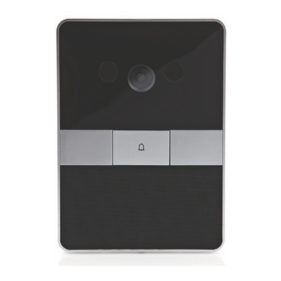
Front Panel Description
Figure 1. Front Faceplate
1
4
2
3
1
Camera. 640 x 480 wide angle. Used for Video
Intercom.
2
Call button. Used to call the person inside the
unit or in another room.
3
Speaker. Used for Audio and video intercom.
4
Microphones (2). Used for audio and video
intercom.
4
1
Advertisement
Table of Contents

Related Manuals for Control 4 Door Station - Interior


Summary of Contents for Control 4 Door Station - Interior
-
Page 1: Specifications
Contact your Control4 Dealer immediately if any parts are missing or if any components are damaged. • Control4 Door Station - Interior faceplate (model C4-DSC-EN-INT) Camera. 640 x 480 wide angle. Used for Video • Mounting screws, security head (5) Intercom. -
Page 2: Pre-Installation
™ This device is to be used for building interior installations only. Find the best location for the Door Station. See Door Station - Interior “Mounting Tips” below. Install the Door Station Back Box. See the Door Setup Guide Station Back Box Installation Guide for details. -
Page 3: Mounting Tips
Mounting Tips Please read the next sections, “Power Options” and “Network and Power Installations” to choose an installation option that works best with the system Follow these tips for the best results. before installing the Door Station. Install the Door Station in a place where it will be protected from water. - Page 4 Power and Network Installations Option 2: Ethernet Connection with AC Power Choose one of these six (6) options to connect the This option sets up Ethernet and AC power. Door Station’s wiring: • Ethernet with PoE (preferred) To install the Door Station with Ethernet and AC • Ethernet with AC power: • Ethernet with DC...
- Page 5 To install the Door Station with WiFi and AC power: To install the Door Station with Ethernet and DC power: Connect the neutral (N) (-) and hot (L) (+) wires Plug the Ethernet cable into the Door Station to the AC power source for the Door Station (see Figure 5).
- Page 6 Option 5: WiFi Connection with DC Power Figure 7. WiFi with DC Power Antenna This option sets up WiFi and DC power. Ensure that you have WiFi in the home. NOTE: WiFi requires an antenna (sold separately). To install the Door Station with WiFi and DC power: Connect the negative (-) and positive (+) wires to the DC power source for the Door Station according to the national and local electrical...
- Page 7 Figure 8. WiFi with PoE the WiFi parameters. See the Composer Pro User WiFi Antenna Guide for details. Reset/Factory Restore the Door Station To reset or factory restore the Door Station: Remove the faceplate and pull the Door Station out from the back box just enough to expose the Reset button (see Figure 2).
- Page 8 Figure 9. 26cm Antenna Kit Figure 11. Antenna to RSMA Connector Antenna Figure 10. 3m Antenna Kit RSMA Connector Thread the other end of the antenna through the back wall of the back box (see Figure 12). Figure 12. Thread Antenna Through Back Box Antenna WiFi Antenna Kit Installation (Optional) Before you install the antenna:...
-
Page 9: Contact And Relay Connections
Thread the other end of the antenna through the Figure 14. Contact/Relay Locations back wall of the back box and through the interior wall as needed (see Figure 12). Carefully insert the Door Station into the back box (see “Attach the Door Station”). Contact and Relay Connections You can connect devices to the contact ports or the To attach the wires to the contacts or relay, select... -
Page 10: Security Best Practices
Security Best Practices • Running MAC address filtering on the router or switch to force a hacker to spoof the Door Station’s MAC address to gain access to the LAN. The Door Station has connections for relays (to open • Configuring the Door Station as WiFi instead of doors, gates, etc.) and contacts. -
Page 11: Regulatory/Safety Information
Regulatory/Safety Information - Utilisant usé ou endommagé les cordons de secteur peuvent avoir comme conséquence la décharge électrique ou le feu. To review regulatory information for your particular - Entrez en contact avec toujours un Control4 products, see the information located on fournisseur des services Control4®...