Table of Contents
Advertisement
SERVICE MANUAL
Ver. 1.2 2009.03
Revision History
Revision History
Revised-2
Replacement of the previously issued
SERVICE MANUAL 9-852-266-12
with this manual.
Link
Link
SPECIFICATIONS
SERVICE NOTE
DISASSEMBLY
BLOCK DIAGRAMS
The components identified by
mark 0 or dotted line with
mark 0 are critical for safety.
Replace only with part num-
ber specified.
HVR-MRC1
9-852-266-13
FRAME SCHEMATIC DIAGRAM
SCHEMATIC DIAGRAMS
PRINTED WIRING BOARDS
Les composants identifiés par une
marque 0 sont critiques pour la
sécurité.
Ne les remplacer que par une pièce
portant le numéro spécifié.
Sony EMCS Co.
HVR-MRC1
REPAIR PARTS LIST
ADJUSTMENTS
INSTRUCTION MANUAL
MEMORY RECORDING UNIT
US Model
Canadian Model
AEP Model
E Model
Chinese Model
Japanese Model
2009C0500-1
© 2009.3
Published by Kohda TEC
Advertisement
Table of Contents

Related Manuals for Sony HVR-MRC1


Summary of Contents for Sony HVR-MRC1
- Page 1 0 are critical for safety. sécurité. Replace only with part num- Ne les remplacer que par une pièce ber specified. portant le numéro spécifié. MEMORY RECORDING UNIT 2009C0500-1 HVR-MRC1 © 2009.3 Sony EMCS Co. 9-852-266-13 Published by Kohda TEC...
- Page 2 HVR-MRC1 : File format HDV recording MPEG-2TS (2 1/4 × 4 × 1 3/8 in.) (.m2t) HVR-MRC1+HVRA-CR1: Approx. 77 × 106 × 51 mm DVCAM/DV recording (3 × 4 1/8 × 2 in.) AVI-Type1 (including the projecting parts) (.AVI) (w/h/d) RAW DV (.DV)
- Page 3 0 °C 40 °C DVCAM/DV -20 °C +60 °C AVI-Type1 .AVI 20 °C 35 °C RAW DV .DV HVR-MRC1 MPEG-2TS 57 102 34 1080/60i , 30p , 24p HVR-MRC1+HVRA-CR1 1080/50i , 25p 77 106 51 2CH MPEG1 Audio Layer2 Stereo...
- Page 4 CRITIQUES POUR LA SÉCURITÉ DE FONCTIONNEMENT. NE COMPONENTS WITH SONY PARTS WHOSE PART NUMBERS REMPLACER CES COMPOSANTS QUE PAR DES PIÈSES SONY APPEAR AS SHOWN IN THIS MANUAL OR IN SUPPLEMENTS DONT LES NUMÉROS SONT DONNÉS DANS CE MANUEL OU PUBLISHED BY SONY.
- Page 5 ENGLISH JAPANESE ENGLISH JAPANESE • • • • • • • • HVR-MRC1 — 5 —...
-
Page 6: Service Note
Fatal error of originating software. Turn this unit off and then back on. Reception buffer overflow. Turn this unit off and then back on. Error code of main CPU firmware. Turn this unit off and then back on. Note: ** is arbitrary value. HVR-MRC1... - Page 7 ENGLISH JAPANESE ENGLISH JAPANESE ERROR A:12:01 HVR-MRC1 1-2E...
- Page 8 • When remove a connector, don’t pull at wire of connector. It is possible that a wire is snapped. pieces of gilt may be left inside) • When installing a connector, don’t press down at wire of connector. It is possible that a wire is snapped. HVR-MRC1...
- Page 9 2-2-2. MAIN CABINET SECTION ⋅ CF Base Cabinet ⋅ CF-110 Board ⋅ TK-071 Board ⋅ LCD Block ⋅ SW-525 Board i.LINK Cradle Cabinet (BATT) Cabinet (CF) ⋅ CR-090 Board - DISASSEMBLY FLOW - 2-2-3. ADAPTOR SECTION ⋅ CR-090 Board ⋅ Cabinet (BATT) HVR-MRC1...
- Page 10 Follow the disassembly in the numerical order given. 1 CF Base Cabinet (1-1 to 1-4) 2 TK-071 Board (2-1 to 2-5) 1-1 (#53) 1 CF Base Cabinet 2-1 (#46) 2 TK-071 Board 1-2 (Claw) Main Cabinet Section (See Page 2-4) 1-3 (Claw) HVR-MRC1...
- Page 11 2 LCD Block 3-7 (#11) 3-3 (#11) Note: Don't touch grease. 3-6 (#46) 3 SW-525 Board Note: On installation of the SW-525 board, adjust the position of switch of CF door and S7010 of SW-525 board. (Boss) (#2) 1-4 (Open) HVR-MRC1...
- Page 12 Follow the disassembly in the numerical order given. 1 CR-090 Board (1-1 to 1-10) 2 Cabinet (BTT) (2-1 to 2-6) 1-1 (#2) 2 Cabinet (BTT) (Open) HELP HELP 2-1 (#12) 1-5 (#12) (#12) 1-7 (#12) 1-9 (#12) 1 CR-090 Board 1-10 1-2 (#12) HVR-MRC1...
- Page 13 HELP Sheet attachment positions and procedures of processing the flexible boards/harnesses are shown. DC-IN Connector/Battery Terminal Harness Hook Battery Terminal Harness DC-IN Connector Harness Terminal Retainer HVR-MRC1 HELP...
-
Page 14: Block Diagrams
3. BLOCK DIAGRAMS Link Link OVERALL BLOCK DIAGRAM POWER BLOCK DIAGRAM HVR-MRC1... - Page 15 SW_PWR SW_PWR SWITCH (4/5) SW_OFF_CN SW_OFF_CN CF_NDASP CARD_DETECT D7009 LED_ON LCD_SDA Q7001 LED_ON REC LAMP, LED DRIVE LCD_SCL CF ACCESS COVER_STAT 3.0V ACV_UNREG H3.3V SET_UNREG M3.3V IC1001 M3.3VA DC CONTROL S3.3V (5/5) P3.3V 1.8V SW_OFF A1.8V : VIDEO/AUDIO SIGNAL HVR-MRC1...
- Page 16 FP-201 FLEXIBLE PWR_CF BOARD Q1018 FB1009 CN4001 CN8002 CN8001 M3.3V IC2004 POWER SWITCH PWR_MAIN_33 Vcc(A06) COMPACT (4/5) FLASH xCD1 PWR_CF0 xCD2 CARD_DETECT 3.3V IC1004 RESET (5/5) IC5002 IC5001 M RESET VDD VOUT RST- EEPROM MAIN CPU (2/5) (2/5) HVR-MRC1 3-2E...
- Page 17 BT901 ND6001 BATTERY TERMINAL CN4001 CN2002 J901 DC IN CN6002 LC-095 BOARD LC-095 BOARD (SIDE A) (SIDE B) FP-201 FLEXIBLE BOARD CN8003 CF-110 BOARD CF-110 BOARD (SIDE A) (SIDE B) CN8004 CN8002 CN8001 COMPACT FLASH CONNECTOR (Compact Flash) HVR-MRC1 FRAME...
-
Page 18: Schematic Diagrams
TK-071 BOARD (3/5) (SDRAM) (HOT SHOE (MEMORY RECORDING UNIT)) FP-203 FLEXIBLE BOARD TK-071 BOARD (4/5) (SUB CPU) (HOT SHOE (i. LINK CRADLE)) CR-090 BOARD TK-071 BOARD (5/5) (DC/DC CONVERTER) (DC IN, HDV/DV CONNECTOR) CF-110 BOARD (CF CONNECTOR) COMMON NOTE FOR SCHEMATIC DIAGRAMS HVR-MRC1... - Page 19 • Voltages and waveforms are measured between the measurement points and ground. They are reference values and reference waveforms. (VOM of DC 10 MΩ input impedance is used) • Voltage values change depending upon input impedance of VOM used.) HVR-MRC1...
- Page 20 ENGLISH JAPANESE 4-2. SCHEMATIC DIAGRAMS ENGLISH JAPANESE 4-2. SCHEMATIC DIAGRAMS (JAPANESE) Ω HVR-MRC1...
- Page 21 DD[2] R4030 DD[2] DD[9] R4031 DD[9] GND(xIOIS16) 0.1u R4032 DD[10] DD[10] C4014 GND(xCD2) LKON R4055 COVER_STAT COVER_STAT FL4002 R4054 R4053 R4052 TK-071 BOARD (1/5) HDV/DV i.LINK INTERFACE XX MARK:NO MOUNT NO MARK:REC/PB MODE R:REC MODE P:PB MODE HVR-MRC1 TK-071 (1/5)
- Page 22 B16 A16 C16 B13 C13 A14 B14 C14 A15 B15 D14 C15 L19 L18 M20 K20 K18 J20 J19 J17 H19 G20 F20 L20 T3 P3 N3 N1 K3 K2 J1 U1 T4 U2 Y17 W17 V20 T18 T20 P20 N19 M18 N18 P19 T19 U20 T17 V16 W16 V14 #DIOW TK-071 BOARD (2/5) MAIN CPU XX MARK:NO MOUNT NO MARK:REC/PB MODE HVR-MRC1 TK-071 (2/5)
- Page 23 DQ26 DDQ[27] DDQ[27] DQ27 DDQ[28] DDQ[28] DQ28 DQM3 DDQ[29] DDQ[29] DQ29 DQM2 DDQ[30] DDQ[30] DQ30 DQM1 DDQ[31] DDQ[31] DQ31 DQM0 DQM0 DQM1 DQM2 DQM3 R3001 #RAS R3002 #CAS CLKE CL3003 CLKD DA[12] DA[11] TK-071 BOARD (3/5) SDRAM HVR-MRC1 TK-071 (3/5)
- Page 24 JL2004 JL2005 JL2006 R2055 RESET C2024 C2023 0.1u JL2007 DATA R2026 10k JL2008 R2023 R2064 MRESET MRESET_R CF_NDASP SLEEP MAIN_TO_SUB LCD_SDA TK-071 BOARD (4/5) LCD_SCL SUB CPU XX MARK:NO MOUNT NO MARK:REC/PB MODE R:REC MODE P:PB MODE HVR-MRC1 TK-071 (4/5)
- Page 25 DTC115TMT2L RB520CS-30T2R CL1002 INVERTER R1025 0.051 L1002 FB1005 4.7uH 0.051 R1026 R1030 C1029 C1031 C1032 C1033 C1027 4.7u 4.7u 4.7u Q1004 6.3V FDS6986AS R1031 SWITCHING R1032 TK-071 BOARD (5/5) DC/DC CONVERTER XX MARK:NO MOUNT NO MARK:REC/PB MODE HVR-MRC1 TK-071 (5/5)
- Page 26 R8026 xREG xREG R8027 R8028 xDASP xDASP R8029 R8030 xPDIAG xPDIAG R8031 R8032 R8033 R8034 CL8003 GND(xIOIS16) xIOIS16 R8036 R8037 GND(xCD2) xCD2 R8038 COVER_STAT S8001 COVER OPEN/CLOSE C8001 D8001 0.01u EDZ-TE61-5.6B CF-110 BOARD CF CONNECTOR XX MARK:NO MOUNT HVR-MRC1 CF-110...
- Page 27 C6009 C6010 VOUT C6011 VSS4 VSS5 VDD4 R6015 R6016 R6017 R6018 R6019 R6020 VDD5 R6021 R6022 VSS6 #RES VDD6 R6023 VSS7 CL6001 CL6002 CL6003 CL6004 CL6005 OSC2 CL6006 OSC1 LC-095 BOARD XX MARK:NO MOUNT NO MARK:REC/PB MODE HVR-MRC1 LC-095 4-10...
- Page 28 STOP (Page 4-7) REC_ON SW_OFF_CN SW_PWR LED_ON 3.3V R7001 S7010 R0/P3.3 D7009 R3.3/P0 CL-196HR-CD-T REC LAMP, Q7001 CF ACCESS DTA144EMT2L POWER LED DRIVE SW-525 BOARD CONTROL SWITCH XX MARK:NO MOUNT NO MARK:REC/PB MODE R:REC MODE P:PB MODE HVR-MRC1 SW-525 4-11...
- Page 29 Note: CN903 (HOT SHOE) is not included in FP-203 flexible board. FP-202 FLEXIBLE BOARD FP-203 FLEXIBLE BOARD HOT SHOE (MEMORY RECORDING UNIT) HOT SHOE (i.LINK CRADLE) (PRINTED WIRING BOARD is omitted) (PRINTED WIRING BOARD is omitted) HVR-MRC1 FP-202, FP-203 4-12...
- Page 30 TPA- TH9003 TPB+ TH9004 HDV/DV TPB- J901 DC IN CN9002 LF9001 F9002 (1.4A/32V) PLUS MINUS_A C9001 C9005 R9003 0.01u LD9001 MINUS_B D9002 MAZS120008SO CHASSIS_GND C9002 C9006 0.01u C9007 CR-090 BOARD DC IN, HDV/DV CONNECTOR XX MARK:NO MOUNT HVR-MRC1 CR-090 4-13...
- Page 31 4-3. PRINTED WIRING BOARDS Link Link TK-071 BOARD SW-525 BOARD CF-110 BOARD CR-090 BOARD LC-095 BOARD COMMON NOTE FOR PRINTED WIRING BOARDS HVR-MRC1...
- Page 32 : pattern of the rear side (The other layers’ patterns are not indicated) • Through hole is omitted. • There are a few cases that the part printed on diagram isn’t mounted in this model. • C: panel designation (JAPANESE) HVR-MRC1 4-14...
- Page 33 C2007 R2053 R2058 R2057 C2016 C2022 R2007 C2008 R2005 R2016 JL2007 R2031 IC2001 C2009 IC2005 R2006 R2015 R2028 R2065 C2010 1-874-877- C2024 R2008 R2014 C2011 R2059 R2009 R2013 C2012 R2012 CL2041 C2013 R2011 CL2042 R2023 R2010 1-874-877- HVR-MRC1 TK-071 4-15...
- Page 34 R8017 R8018 R8019 CL8002 R8021 R8022 R8023 R8024 R8025 R8026 R8027 R8028 R8029 R8030 R8031 R8032 R8033 R8034 CL8003 R8036 R8037 R8038 Note: CN8001 is not supplied, but this is included in CF-110 complete board. 1-874-878- 1-874-878- HVR-MRC1 CF-110 4-16...
- Page 35 POWER 1-874-879- 1-874-880- LC-095 BOARD (SIDE B) CL6030 CN6002 FB6001 C6001 Q6001 C6012 C6013 R6001 R6005 C6002 R6003 R6004 R6023 CL6002 CL6004 CL6006 R6022 R6021 CL6001 CL6003 CL6005 R6020 R6019 R6018 R6017 R6016 R6015 C6003 1-874-879- HVR-MRC1 LC-095, SW-525 4-17...
- Page 36 : Uses unleaded solder. CR-090 BOARD (SIDE A) CN9004 LD9001 CR-090 BOARD (SIDE B) C9007 R9002 R9003 LD9002 CN9005 RB9001 HDV/DV C9005 C9006 D9002 F9002 D9001 C9003 C9004 LF9001 C9001 C9002 CL9001 CL9002 CN9002 CN9001 1-874-881- 1-874-881- HVR-MRC1 CR-090 4-18E...
-
Page 37: Repair Parts List
NOTE: Characters A to Z of the electrical parts list indicate location of exploded views in which the desired part is shown. EXPLODED VIEWS EXPLODED VIEWS Link Link BASE CABINET SECTION MAIN CABINET SECTION ADAPTOR SECTION ELECTRICAL PARTS LIST Link ELECTRICAL PARTS LIST Link ACCESSORIES CF-110 BOARD LC-095 BOARD TK-071 BOARD CR-090 BOARD SW-525 BOARD HVR-MRC1... - Page 38 : Argentine model AUS : Australian model : Brazilian model : Chinese model CND : Canadian model : East European model HK : Hong Kong model : Japanese model : Tourist model : Korea model : North European model HVR-MRC1...
-
Page 39: Exploded Views
Use the correct part for the each camera or model. (See the chart below) Note: Part No. Main Model Description HVR-Z7J * A-1700-861-A HVR-S270J SERVICE (HVR-MRC1 MAIN J) HVR-MRC1K (J) HVR-Z7U * A-1700-862-A HVR-S270U SERVICE (HVR-MRC1 MAIN U) HVR-MRC1K (US, CND) HVR-Z7N * A-1700-863-A... - Page 40 A-1544-473-A LC-095 BOARD, COMPLETE (SERVICE) 3-290-930-01 HOLDER, LCD * 71 2-697-881-01 DAMPER, LCD 2-635-562-31 SCREW (M1.7) (Black) * 61 3-290-929-01 SHEET, CF REFLECTION 3-078-890-11 SCREW, TAPPING (Silver) * 62 3-290-927-01 LIGHT, GUIDE 2-660-401-11 SCREW (M1.7), NEW TRU-STAR, P2 (Red) HVR-MRC1...
- Page 41 1-785-247-31 CONNECTOR, DC-IN * 107 3-290-985-01 PLATE, TRIPOD RETAINER 2-635-562-11 SCREW (M1.7) (Black) 3-290-986-01 GUIDE, TRIPOD 2-635-562-31 SCREW (M1.7) (Black) 2-664-982-01 SCREW, TRIPOD 3-080-204-21 SCREW, TAPPING, P2 (Black) X-2188-923-1 CABINET (BATT) ASSY 3-080-206-21 SCREW, TAPPING, P2 (Black) 2-697-897-01 COVER, DC-IN HVR-MRC1...
-
Page 42: Electrical Parts List
1/16W < RESISTOR > R6010 1-208-952-81 METAL CHIP 510K 0.5% 1/16W R6011 1-218-971-11 RES-CHIP 1/16W R9002 1-216-864-11 SHORT CHIP R6012 1-218-971-11 RES-CHIP 1/16W R9003 1-216-864-11 SHORT CHIP R6013 1-218-971-11 RES-CHIP 1/16W • Refer to page 5-1 for mark 0. HVR-MRC1... - Page 43 1-112-717-91 CERAMIC CHIP 6.3V S7007 1-771-844-21 SWITCH, TACTILE (REPEAT) C1047 1-112-717-91 CERAMIC CHIP 6.3V S7008 1-771-844-21 SWITCH, TACTILE (>, EXEC m) C1048 1-112-717-91 CERAMIC CHIP 6.3V S7009 1-771-844-21 SWITCH, TACTILE (REC) C1049 1-112-717-91 CERAMIC CHIP 6.3V C2001 1-100-567-81 CERAMIC CHIP 0.01uF HVR-MRC1...
- Page 44 1-125-777-11 CERAMIC CHIP 0.1uF FB1009 1-400-331-11 FERRITE, EMI (SMD) (1005) FB1010 1-400-619-11 BEAD, FERRITE (CHIP) (1608) C5006 1-125-777-11 CERAMIC CHIP 0.1uF C5007 1-125-777-11 CERAMIC CHIP 0.1uF FB2001 1-400-915-21 INDUCTOR (EMI FERRITE) (2012) • Refer to page 5-1 for mark 0. HVR-MRC1...
- Page 45 IC5002. It is included in TK-071 complete board * Q1011 6-551-600-01 TRANSISTOR DTC115EETL though neither of these are supplied. Q1012 6-550-354-01 TRANSISTOR RTQ035P02TR * Q1013 6-551-600-01 TRANSISTOR DTC115EETL Note: Q1014 6-550-119-01 TRANSISTOR DTC144EMFS6T2L Q1015 6-551-067-01 TRANSISTOR RTF015P02TL • Refer to page 5-1 for mark 0. HVR-MRC1...
- Page 46 1/16W R4018 1-208-861-81 METAL CHIP 0.5% 1/16W R5040 1-208-911-11 METAL CHIP 0.5% 1/16W R4019 1-208-861-81 METAL CHIP 0.5% 1/16W R5041 1-208-911-11 METAL CHIP 0.5% 1/16W R4020 1-218-935-11 RES-CHIP 1/16W R4021 1-208-861-81 METAL CHIP 0.5% 1/16W R5046 1-218-941-81 RES-CHIP 1/16W HVR-MRC1...
- Page 47 TK-071 Ref. No. Part No. Description Ref. No. Part No. Description < VIBRATOR > X4001 1-781-045-21 VIBRATOR, CRYSTAL (24.576MHz) * X5001 1-813-856-11 OSCILLATOR, CRYSTAL (27MHz) HVR-MRC1 5-10...
- Page 48 Checking supplied accessories. CD-ROM (Note) “Manuals for Digital HD Video Camera Recorder” Operating Instructions (PDF) Note:HVR-MRC1 is the accessory of HDR-Z7J/Z7U/Z7N/Z7E/Z7P/ The CD-ROM supplied contains all of language version of Z7C and HDR-S270J/S270U/S270N/S270E/S270P/S270C. the Operating Instructions (PDF) for printing. Please refer to following CD-ROM that is those accessory for The printed matter is not supplied.
- Page 49 (DK-215) PC with i.LINK cable IEEE1394 terminal AC Adapter/Charger HVR-MRC1 Fig. 6-1-1 Procedures 1) Attach the iLINK cradle (HVRA-CR1) to the set. 2) Connect the set to the PC with the i.LINK cable. Note: Remove the Compact Flash card if it has been inserted in the set.
- Page 50 CPU: MMX Pentium 200 MHz or faster IEEE1394 terminal (DV connector) Note 2: Retrieve the batch file etc. used from the item of “ESI Jig & Software” of “ESI homepage” by the following conditions Model Name: HVR-MRC1 Category: MPU/ROM/Software HVR-MRC1...
- Page 51 Installation of Driver 6. Select “Add a new hardware device” and click “Next”. Install the driver exclusive for confirmation of HVR-MRC1. Install the driver in the following procedures. Once this work is performed, further installation is not required later on.
- Page 52 11. Select “1394vdev.inf” copied to the PC and click “Open”. 14. Click “Next”. Then, the installation starts. Fig. 6-1-10 Fig. 6-1-13 Note: When driver is installed, personaol computer might be re- set. In this case, please proceed work from procedure 15 after starting the personal computer. HVR-MRC1...
- Page 53 18. Right-click “Unknown devices” and select “Update Driver”. Fig. 6-1-14 16. If “1394 Virtual device” is displayed below “1394 Test De- vices”, the installation is normally finished. Fig. 6-1-17 19. Select “Install from a list or specific location” and click “Next”. Fig. 6-1-15 Fig. 6-1-18 HVR-MRC1...
- Page 54 23. Open “Device Manager”. If “1384 Virtual Devices” is displayed below “1394 Test Devices”, the installation is normally fin- ished. Fig. 6-1-19 21. Specify the location (Uploader) where the driver is saved and click “OK”. Fig. 6-1-21 The installation starts. Fig. 6-1-20 HVR-MRC1...
- Page 55 If you execute HISTORY_E.bat with the HISTORY.TXT al- ready created, new history information will be added to the HISTORY.TXT with previously read history information re- mained unchanged. HVR-MRC1...
- Page 56 Fig. 6-1-27 Fig. 6-1-29 4. Press the [ENTER] key of PC to close the command prompt 4. Press the [ENTER] key of PC to close the command prompt window. window. HVR-MRC1...
- Page 57 Fig. 6-1-31 Fig. 6-1-33 4. Press the [ENTER] key of PC to close the command prompt 4. Press the [ENTER] key of PC to close the command prompt window. window. HVR-MRC1...
- Page 58 3. When the clearing of accumulated CF detection count finished, the following message will be displayed in the command prompt window. Fig. 6-1-35 4. Press the [ENTER] key of PC to close the command prompt window. HVR-MRC1 6-10E...
-
Page 59: Operating Instructions
The model number and the serial number are located at the name plate on the left of the unit. Record the serial number in the space provided below. Refer to these numbers whenever you call upon your Sony dealer regarding this product. Model No. HVR- Serial No. -
Page 60: Table Of Contents
• “InfoLITHIUM” is a trademark of Sony Corporation. Table of contents • i.LINK and are trademarks of Sony Corporation. • HDV and the HDV logo are trademarks of Sony Corporation and Victor Company of Japan, Ltd. • Microsoft, Windows, Windows Vista and Windows Media are either registered trademarks or trademarks of Microsoft Overview ............ -
Page 61: Overview
Overview Integrated architecture to the camcorder Supported models • The body is small and light with a weight of about 130 g • This unit can be connected to a camcorder via a special and connects directly to a camcorder without a cable to interface. -
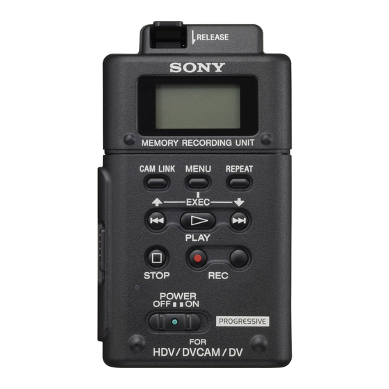
Page 62: Names Of Parts
Names of parts Memory Recording Unit / i.LINK Cradle Attaching to the i.LINK cradle Attach this unit to the i.LINK cradle by sliding the unit in the direction of the arrow. 1 RELEASE button 9 PLAY/EXEC button Press this button to remove this unit. Press this button to play recorded files. -
Page 63: Video Mode
LCD screen display VIDEO mode During recording During playback 2 3 4 1 Power supply display 8 Status display This icon is not displayed when this unit is connected Displays the status with an icon. directly to the camcorder. x Power is on and playback/recording is stopped Displays the power supply icons when connected to a PC z Recording or camcorder using the i.LINK cradle. -
Page 64: Using In Video Mode
• Although this unit has been tested with CompactFlash, Sony does not guarantee its operation with all CompactFlash. The operation of this unit with Sony CompactFlash has CompactFlash capacity and available been checked. recording time • CompactFlash with 133x 2GB or more specifications are recommended for this unit. -
Page 65: Menu Organization (Video Mode)
Menu organization (VIDEO mode) root CLIP SELECT DELETE CLIP FORMAT REC MODE NORMAL CACHE INTERVAL LOOP i.LINK MODE AUTO SETTING TC FORMAT AUTO DV FILETYPE RAW DV INTERVAL REC TIME 0.5sec 1sec 1.5sec 2sec INT.TIME 30sec 1min 5min 10min CAMLINK SEL FOLLOW SYNCHRO SLEEP MODE... - Page 66 CAMERA NO SETTING You can assign a number to the data clip name when recording. TC FORMAT Use this mode to assign non-overlapping numbers to clip Follows the DF/NDF of the time code from the camcorder names recorded simultaneously on more than one camcorder, connected to this unit.
-
Page 67: Recording Images From The Camcorder To This Unit
Recording images from the camcorder to this unit Images recorded by the camcorder can be recorded onto this x Recording video simultaneously on this unit and unit. a camcorder – Connecting to a camcorder with an “external REC control” function (SYNCHRO mode) Recording images When connected to a camcorder that has an external REC (POWER switch at the ON side) - Page 68 x Recording on this unit during camcorder tape Cache recording mode replacement The most recent approximately maximum 14 seconds of When connected to a camcorder that has an external REC video and audio captured by the camcorder are held in a control function, you can record video on this unit only buffer memory and automatically recorded when the while changing the tape of the camcorder.
- Page 69 Loop recording mode Repeats overwrite-recording using the available space on the CompactFlash. You cannot select this mode if the remaining recording time is less than 5 minutes (CompactFlash icon is flashing). Setting loop recording mode Select [LOOP] from [REC MODE] on the menu screen. LCD screen display in loop recording mode Remains on during recording Notes...
-
Page 70: Playback The Image Recorded On A Compactflash In This Unit
Playback the image recorded on a CompactFlash in this unit To play back video clip recorded on a CompactFlash in this Trick playback unit, you need to connect this unit to a playback device via an i.LINK cable. When the playback image is output to i.LINK, the clip is played at 3x, 6x, and 9x the normal speed. -
Page 71: Useful Functions In Combination With Hvr-Z7/S270
You can record the time code of the HVR-Z7/S270 without a Useful functions in combination tape in the HVR-Z7/S270. with HVR-Z7/S270 If you want to record video using the time code of the HVR-Z7/S270, set the time code setting of the Tapeless external REC control HVR-Z7/S270 as follows. - Page 72 Display the operational status of this unit on the HVR-Z7/S270 LCD screen CAMERA mode – Indicators – Status check indicator • The following information can be displayed on the LCD • The following information can be displayed on the status screen of the HVR-Z7/S270.
- Page 73 VCR mode – Indicators – Status check indicator • The following information can be displayed on the LCD • The following information can be displayed on the status screen of the HVR-Z7/S270. check indicator (VCR mode) of the HVR-Z7/S270. 1 CompactFlash connecting status PB FORMAT This icon blinks when the remaining recording time of the Displays the playback format of this unit.
-
Page 74: Using In Computer Mode
Using in COMPUTER mode Connecting to a computer You can transfer recorded images on this unit as a file in HDV or DV format to a nonlinear editing system or computer. Attach the HVRA-CR1 i.LINK cradle and optional AC adaptor to this unit. For extended use, the AC adaptor is recommended. -
Page 75: Menu Organization (Computer Mode)
Menu organization (COMPUTER mode) root DV-NTSC DV-PAL DRIVE SETTING TC FORMAT AUTO DV FILETYPE RAW DV CAMERA NO *Boldface settings are default settings. Notes • For the following cases, operate “Safety remove Device (for Operate in the VIDEO mode. Set this mode when reading or Windows)”... -
Page 76: Folder Saving Format
• Segmented files recorded from HDV stream Some computer applications cannot play back the transitions between segmented files properly. If this happens, join the files using the “Sony Recording Unit Utility” or “M2T File Connection Tool” (*). * Available from the Sony support page... -
Page 77: Notes Regarding Computer Mode
Notes regarding COMPUTER mode • Do not save other data files in the HVR folder. • Do not transfer data from a computer to this unit in COMPUTER mode. Write back data from a computer to this unit by streaming. Write back data after selecting HDV or DV-NTSC, DV-PAL format in PC MODE in the menu. -
Page 78: Power Supply
Power supply Remaining battery time indication in the AC Preparing the power supply adaptor/charger display window This indication is provided by data communications between The following will explain the optional AC-VQ1050 AC the AC adaptor/charger and the “InfoLITHIUM” battery adaptor/charger. pack. - Page 79 AC adaptor/charger To connect this unit to a wall outlet Do not short-circuit the DC plug of the AC adaptor/charger For prolonged operation, such as playing the recorded or battery terminal with any metallic objects. This may cause images, you can operate this unit from a domestic wall outlet a malfunction.
-
Page 80: Trouble Shooting
• During repair work, Sony may perform a minimal check of the data on a CompactFlash in order to verify improvements or the occurrence of defective symptoms. However, Sony never copies or saves the data. -
Page 81: Connecting A Computer
Connecting a computer Symptom Cause/Remedy t Set the computer display as follows: An error message appears when you – 1024 × 768 dots or more, high color (16 bits, 65,000 colors) or more. place the supplied CD-ROM in your computer. •... -
Page 82: Warning Indicators
Self-diagnosis display When an error occurs the following warning indicators may appear on the LCD screen. Message Cause/Corrective Action If an error recurs after you repeat corrective action several times, contact Sony A:ss:ss/I:ss:ss/P:ss:ss/ Customer Service or the place of purchase. M:ss:ss/F:ss:ss/X:ss:ss... -
Page 83: Caution Message
CompactFlash to a computer or other suitable media. If the above symptoms do not improve, try with a different CompactFlash. If the above symptoms still do not improve even several attempts are made, contact your Sony dealer. -
Page 84: About I.link
• i.LINK is an easy-to-remember term for the IEEE 1394 disconnect the i.LINK cable. Changing the format after proposed by Sony, and is a trademark approved by many connecting the i.LINK cable, the video signal may not be corporations in Japan and overseas. -
Page 85: Optional Compactflash
Optional CompactFlash CompactFlash • A CompactFlash 133x 2 GB or higher is recommended for use with this unit. (A speed of less than 133x is not guaranteed; space less than 2GB is not guaranteed.) • When using a CompactFlash for the first time, be sure to format it with this unit. -
Page 86: Specifications
Approx. 57 × 102 × 34 mm HVR-MRC1 : (2 1/4 × 4 1/8 × 1 3/8 in.) HVR-MRC1+HVRA-CR1: Approx. 77 × 106 × 51 mm (3 1/8 × 4 1/4 × 2 1/8 in.) (including the projecting parts) (w/h/d) -
Page 87: Precautions
If this unit gets wet, it may permanently cause malfunction. • If any solid object or liquid gets inside the casing, unplug this unit and have it checked by a Sony dealer before operating it any further. • Avoid rough handling, disassembling, modifying, physical shock, or impact such as hammering, dropping or stepping on this unit. -
Page 88: Getting The Best Performance From The Battery Pack
Getting the best performance from the battery pack • If the ambient temperature is low, the battery pack performance deteriorates, reducing the operating time. To maximize the operating time, the following techniques are recommended. – Keep the battery pack warm in a pocket, and load it into the unit immediately before shooting. - Page 89 Additional information on this product and answers to frequently asked questions can be found at our Customer Support Website.
- Page 90 HARDWARE LIST (1/7) #1: M1.7 X 2.5 #2: M1.7 X 4.0 #3: M1.7 X 2.5 #4: M1.4 X 2.5 (Tapping) (Black) (Black) (Red) (Dark Silver) 2-635-562-11 2-635-562-31 2-660-401-01 3-348-998-81 #5: M1.7 X 3.5 (Tapping) #6: M1.4 X 1.7 #7: M1.7 X 1.6 #8: M1.7 X 3.5 (Tapping) (Black) (Silver)
- Page 91 HARDWARE LIST (2/7) #21: M1.4 X 3.0 #22: M1.7 X 5.0 (Tapping) #23: M1.7 X 4.0 (Tapping) #24: B1.7 X 5.5 (Tapping) (Black) (Silver) (Black) (Black) 2-662-396-21 3-083-261-01 3-080-204-11 4-679-805-11 #25: M1.7 X 3.0 #26: M1.4 X 2.0 #27: M1.4 X 2.0 #28: M1.4 X 4.0 (Tapping) (Black) (Silver)
- Page 92 HARDWARE LIST (3/7) #41: M3.0 X 8.0 (Tapping) #42: M2.0 X 4.0 (Tapping) #43: M1.7 X 4.0 #44: M1.7 X 3.0 (Tapping) (Silver) (Silver) (Red) (Silver) 3-065-748-01 7-628-253-00 2-660-401-31 3-078-890-61 #45: M1.4 X 2.5 #46: M1.7 X 3.0 #47: M1.4 X 3.0 (Tapping) #48: M1.7 X 2.5 (Silver) (Red)
- Page 93 HARDWARE LIST (4/7) #64: M1.7 X 5.0 (Tapping) #61: M3.0 X 10.0 #62: M2.0 X 3.0 #63: M5.0 X 12.5 (Silver) (Black) (Silver) (Black) 2-666-551-21 7-682-549-09 3-080-202-21 3-060-811-21 12.5 10.0 #65: M1.4 X 3.5 #66: M1.4 X 1.4 #67: M1.4 X 2.0 #68: M1.7 X 4.0 (Silver) (Silver)
- Page 94 HARDWARE LIST (5/7) #81: M1.7 X 2.5 #82: M1.4 X 1.4 #83: M1.7 X 7.0 (Tapping) #84: M2.0 X 3.0 (Silver) (Silver) (Black) (Silver) 2-515-756-01 3-272-251-01 3-080-204-41 3-072-453-11 #85: M1.7 X 2.5 #86: M1.7 X 4.0 (Tapping) #87: M1.6 X 5.3 #88: M1.6 X 5.9 (Tapping) (Black) (Silver)
- Page 95 HARDWARE LIST (6/7) #101: M2.0 X 5.0 #102: M2.6 X 8.0 #103: M2.6 X 10.0 #104: M3.0 X 8.0 (Silver) (Black) (Silver) (Black) 7-621-555-39 7-621-284-30 7-685-794-09 7-682-548-09 10.0 #105: M2.0 X 4.0 #106: M2.0 X 6.0 #107: M2.0 X 5.0 #108: M1.7 X 3.0 (Tapping) (Red) (Black)
- Page 96 HARDWARE LIST (7/7) #121: M2.0 X 4.0 (Tapping) #122: M3.0 X 6.0 #123: M4.0 X 8.0 #124: M1.7 X 2.0 (Silver) (Black) (Black) (Silver) 7-682-547-09 3-080-205-11 7-682-561-09 2-599-475-01...
-
Page 97: Revision History
— 2008.06 Revised-1 • Change of Repair Parts (A1 DI08-162) S.M. revised: Page 5-5, Page 5-6, Page 5-7 2009.03 Revised-2 • Change of Repair Parts (A2 DI08-386) S.M. revised: Page 5-2, Page 5-3, Page 5-4, Page 5-5, Page 5-7 HVR-MRC1...