Table of Contents

Related Manuals for Panasonic DMR-EH50P


Summary of Contents for Panasonic DMR-EH50P
- Page 1 ORDER NO.DSD0503038C1 DVD Video Recorder DMR-EH50P DMR-EH50PC Vol. 1 Colour (S).......S ilver Type © 2005 Matsushita Electric Industrial CO., Ltd. All rights reserved. Unauthorized copying distribution is a violation of law.
- Page 2 DMR-EH50 P / DMR-EH50 PC...
-
Page 3: Table Of Contents
DMR-EH50 P / DMR-EH50 PC CONTENTS Page Page 1 Specifications 15.2. When the unit does not operate normally after replacing 2 Safety precautions the Timer Microprocessor or Main P.C.B. 2.1. General guidelines 16 Standard Inspection Specifications after Making Repairs 2.2. Caution for fuse replacement 17 Voltage and Waveform Chart 3 Prevention of Electrostatic Discharge (ESD) to Electrostatic 17.1. -
Page 4: Specifications
DMR-EH50 P / DMR-EH50 PC 1 Specifications... -
Page 5: Safety Precautions
DMR-EH50 P / DMR-EH50 PC 2 Safety precautions 2.1. General guidelines 1. When servicing, observe the original lead dress. If a short circuit is found, replace all parts which have been overheated or damaged by the short circuit. 2. After servicing, see to it that all the protective devices such as insulation barriers, insulation papers shields are properly installed. -
Page 6: Prevention Of Electrostatic Discharge (Esd) To Electrostatic Sensitive (Es) Devices
DMR-EH50 P / DMR-EH50 PC 3 Prevention of Electrostatic Discharge (ESD) to Electrostatic Sensitive (ES) Devices Some semiconductor (solid state) devices can be damaged easily by static electricity. Such components commonly are called Electrostatic Sensitive (ES) Devices. Examples of typical ES devices are integrated circuits and some field-effect transistor- sand semiconductor "chip"... -
Page 7: Precaution Of Laser Diode
DMR-EH50 P / DMR-EH50 PC 4 Precaution of Laser Diode... -
Page 8: How To Replace The Lithium Battery
DMR-EH50 P / DMR-EH50 PC 5 How to replace the Lithium Battery REPLACEMENT PROCEDURE 1. Remove the Top case and DVD-RAM drive unit with Main P.C.B. by referring the Disassemblin g Procedure. 2. Unsolder the Lithium Batteries: B7501 and then replace it into new one. ( As shown in 21.2.4. -
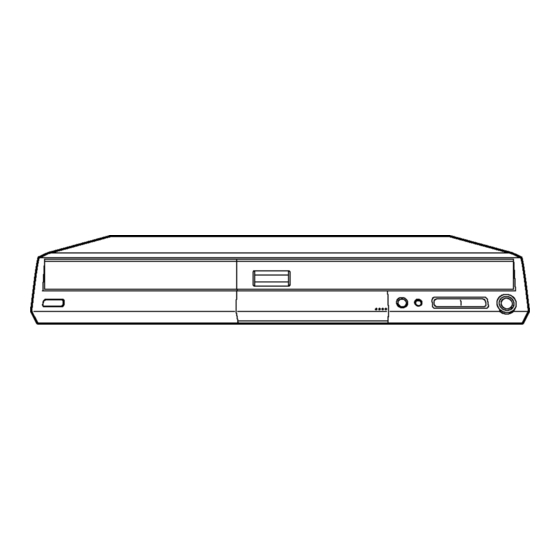
Page 9: Each Button
DMR-EH50 P / DMR-EH50 PC 7 Each Button... - Page 10 DMR-EH50 P / DMR-EH50 PC...
-
Page 11: New Feature
DMR-EH50 P / DMR-EH50 PC 8 New Feature 8.1. Quick start function(REC) 1. General A few seconds after tuning on the unit,you can start recording to DVD-RAM,HDD. You can switch the operation of this function (ON/OFF) on the menu screen. . 2. -
Page 12: Taking Out The Disc From Ram-Drive Unit When The Disc Cannot Be Ejected By Open/Close Button
DMR-EH50 P / DMR-EH50 PC 9 Taking out the Disc from RAM-Drive Unit when the Disc cannot be ejected by OPEN/CLOSE button 9.1. Forcible Disc Eject 9.1.1. When the power can be turned off. 1. Turn off the power and press [STOP] [CH UP] keys on the front panel simultaneous ly for 5 seconds. 9.1.2. -
Page 13: Service Explorer
DMR-EH50 P / DMR-EH50 PC 10 Service Explorer Confirm “RAM-Drive Last Error” in Service Mode Execute Service Mode 1. Press [REC], [CH UP] and [OPEN/CLOSE] simultaneous ly for 5 seconds when P-off. FL Display: *After finishing display “(7). Factor of Drive Error occurring”, press [0] [2] ~[1] [9] keys of the Remote Controller so that 19 memories can be displayed as maximum. - Page 14 (5) Error occurring Disc type is displayed for 5 seconds. (6) Disc Maker´s ID is displayed for 5 seconds. Example of Disc Maker´s ID: DVD-R Disc FL Display (Disc Maker´s ID) Disc Maker Country Panasonic Japan Pioneer Japan Mitsubishi Chemical Corporation Japan Japan...
- Page 15 DMR-EH50 P / DMR-EH50 PC Error Occurring Disc State...
-
Page 16: Self-Diagnosis And Special Mode Setting
DMR-EH50 P / DMR-EH50 PC 11 Self-Diagnosis and Special Mode Setting 11.1. Self-Diagnosis Functions Self-Diagnosis Function provides information for errors to service personnel by “Self-Diagno sis Display” when any error has occurred. U**, H** and F** are stored in memory and held. You can check latest error code by transmitting [0] [1] of Remote Controller in Service Mode. -
Page 17: Special Modes Setting
DMR-EH50 P / DMR-EH50 PC Error Code Diagnosis contents Description Monitor Display Automatic FL display UNFORM Unformatted disc error You have inserted an unformatted DVD-RAM or DVD-RW that is unformatted or recorded on other equipment. PLEASE Unit is in termination process Unit is in termination process now. - Page 18 DMR-EH50 P / DMR-EH50 PC Item FL display Key operation Mode name Description Front Key Aging Contents (Example): CAUTION: Condition of the following sequence execution. *At start, DVD should be selected. Demonstration Ejection of the disc is prohibited. *When lock the tray. When the power is on, press lock/unlock [STOP]...
-
Page 19: Service Modes
DMR-EH50 P / DMR-EH50 PC 11.3. Service Modes Service mode setting: While the power is off, press REC, CH UP and OPEN / CLOSE simultaneous ly for five seconds. Item FL display Key operation Mode name Description (Remote controller key) Release Items Item of Service Mode executing is cancelled. - Page 20 DMR-EH50 P / DMR-EH50 PC Item FL display Key operation Mode name Description (Remote controller key) Audio Mute (XTMUTE) Check whether mute is applied normally by Press [2] [1] in service mode. the timer microprocessor. Audio Mute (XDMUTE) Check whether mute is applied normally by Press [2] [2] in service mode.
- Page 21 DMR-EH50 P / DMR-EH50 PC Item FL display Key operation Mode name Description (Remote controller key) RAM Drive Last Error RAM Drive error code display. 1. Error Number is displayed for 5 Press [4] [2] in service mode. seconds. *For details about the drive error code, refer When “INFO******”...
- Page 22 DMR-EH50 P / DMR-EH50 PC Item FL display Key operation Mode name Description (Remote controller key) Display the Error History Display the Error History stored on the unit. Display reason of error for 5 Press [6] [5] in service mode. seconds.
-
Page 23: Assembling And Disassembling
DMR-EH50 P / DMR-EH50 PC 12 Assembling and Disassembling 12.1. Disassembly Flow Chart The following chart is the procedure for disassemblin g the casing and inside parts for internal inspection when carrying out the servicing. To assemble the unit, reverse the steps shown in the chart below. 12.2. -
Page 24: Top Cover
DMR-EH50 P / DMR-EH50 PC 12.3. Top Cover 12.5. SD Card P.C.B. 1. Remove the 2 screws (A) and 3 screws (B). 1. Remove 2 Screws (A) to remove SD Card P.C.B. 2. Slide Top Cover rearward and open the both ends at rear side of the Top Cover a little and lift the Top Cover in the direction of the arrows. -
Page 25: Dvd-Ram Drive
DMR-EH50 P / DMR-EH50 PC CAUTION: 12.8. HDD When replacing Digital P.C.B., pay attention as below. Handling of HDD The following precautions should be taken when handling HDD. 1. Never give an impact to HDD. (Even a drop from 1cm height can be a cause of HDD failure. -
Page 26: Led P.c.b
DMR-EH50 P / DMR-EH50 PC 4. Remove 4 screws to remove HDD 12.9. LED P.C.B. 1. Remove a Screw (A) to remove SD Card P.C.B. Angle. 2. At first disconnect the connector on one side as shown below, and pull out LED P.C.B. 12.10. -
Page 27: Rear Panel
DMR-EH50 P / DMR-EH50 PC 2. Remove 3 Screws (B) and disconnect Connector (A) and 3. Unlock 2 Locking Tabs (A) to remove Rear Panel. HDD Power Connector to remove Power P.C.B. 12.11.1. Fan Motor 1. Disconnect Fan Connector and remove 2 Screws (A). 2. -
Page 28: Main
DMR-EH50 P / DMR-EH50 PC 12.13. Main P.C.B. 1. Disconnect Connector (A) for Front (L) P.C.B. 2. Remove 5 Screws (A),. 3. Remove Power P.C.B. Angle, Digital P.C.B. Angle and SD Card P.C.B. Angle and disconnect Connector (A) to remove Main P.C.B. -
Page 29: Service Fixture And Tools
DMR-EH50 P / DMR-EH50 PC 13 Service Fixture and Tools Part Number Description Compatibility RFKZ0125 Extension FFC (Digital P.C.B. - DVD-RAM Drive / 40 Pin) Same as E50/ E55 series RFKZ0126 Extension Cable (MainP.C.B. - DVD-RAM Drive/ 4 Pin) Same as E30/HS2 series RFKZ0216 Extension Cable (MainP.C.B. -
Page 30: Checking And Repairing Of Digital P.c.b
DMR-EH50 P / DMR-EH50 PC 14.2. Checking and Repairing of Digital P.C.B. -
Page 31: Checking And Repairing Of Main P.c.b
DMR-EH50 P / DMR-EH50 PC 14.3. Checking and Repairing of Main P.C.B. - Page 32 DMR-EH50 P / DMR-EH50 PC 14.3.1. Checking IR Circuit NOTE1: Even if Main P.C.B. is not removed, IR Circuit can be checked. NOTE2: Prepare the Oscilloscope 1. Remove Top Case. 2. Turn on the power. Then if "Welcome ..." was displayed on the TV monitor, press [ENTER] to advance next stage. Then press [ENTER] and proceed to step 6.
-
Page 33: Checking And Repairing Of Dvd-Ram Drive
DMR-EH50 P / DMR-EH50 PC 14.4. Checking and Repairing of DVD-RAM Drive... -
Page 34: Checking And Repairing Of Hdd
DMR-EH50 P / DMR-EH50 PC 14.5. Checking and Repairing of HDD... -
Page 35: Caution After Replacing Parts
Perform auto recording and playback for one minute using the RAM No abnormality should be seen in the picture, sound or operation. disc. *Panasonic DVD-RAM disc should be used when recording and playback. Model with the HDD: Perform auto recording and playback for one No abnormality should be seen in the picture, sound or operation. -
Page 36: Voltage And Waveform Chart
DMR-EH50 P / DMR-EH50 PC 17 Voltage and Waveform Chart Note) Circuit voltage and waveform described herein shall be regarded as reference information when probing defect point, because it may differ from an actual measuring value due to difference of Measuring instrument and its measuring condition and product itself. - Page 37 DMR-EH50 P / DMR-EH50 PC IC3001 Ref No. MODE PLAY STOP Ref No. IC4001 MODE PLAY STOP IC4001 Ref No. MODE PLAY STOP IC4004 IC4005 IC7404 Ref No. MODE 12.9 PLAY 12.9 STOP 12.9 IC7501 Ref No. MODE -27.8 -27.8 -27.8 -27.8 -27.8...
-
Page 38: Tuner P.c.b
DMR-EH50 P / DMR-EH50 PC Ref No. IC8002 MODE PLAY STOP Q4001 Q4002 Q4003 Q4004 Q4005 Ref No. MODE -0.2 -0.2 -0.2 -0.4 -0.3 PLAY -0.2 -0.2 -0.2 -0.4 -0.3 STOP -0.2 -0.3 -0.3 -0.3 -0.2 Q7503 Q7504 Q7506 Q7507 Q7508 Ref No. -
Page 39: P9001 Connector
DMR-EH50 P / DMR-EH50 PC 17.5. P9001 Connector P9001 Ref No. MODE PLAY STOP P9001 Ref No. MODE PLAY STOP Ref No. P9001 MODE PLAY STOP P9001 Ref No. MODE PLAY STOP P9001 Ref No. MODE PLAY STOP... -
Page 40: Waveform Chart
DMR-EH50 P / DMR-EH50 PC 17.6. Waveform Chart T1150-2 STOP T1150-6 STOP T1150-10,11 STOP T1150-4 STOP 30Vp-p (5 sec.div) 30Vp-p (5 sec.div) 300Vp-p (5 sec.div) 20Vp-p (5m sec.div) IC1150-1 STOP IC1150-2 STOP P7401-83 REC/PLAY P7401-51 REC/PLAY 8.0Vp-p (5 sec.div) 0.5Vp-p (5 sec.div) 1.0Vp-p (20 sec.div) 0.8Vp-p (20 sec.div) P7401-59 REC/PLAY... -
Page 41: Abbreviations
DMR-EH50 P / DMR-EH50 PC 18 Abbreviations INITIAL/LOGO ABBREVIATIONS INITIAL/LOGO ABBREVIATIONS A0~UP ADDRESS ERROR TORQUE CONTROL ACLK AUDIO CLOCK ERROR TORQUE CONTROL AD0~UP ADDRESS BUS REFERENCE ADATA AUDIO PES PACKET DATA ENCSEL ENCODER SELECT ADDRESS LATCH ENABLE ETMCLK EXTERNAL M CLOCK (81MHz/40.5MHz) AMUTE AUDIO MUTE ETSCLK... - Page 42 DMR-EH50 P / DMR-EH50 PC INITIAL/LOGO ABBREVIATIONS INITIAL/LOGO ABBREVIATIONS READ ENABLE VBLANK V BLANKING RFENV RF ENVELOPE COLLECTOR POWER SUPPLY RF PHASE DIFFERENCE OUTPUT VOLTAGE (CD-ROM) REGISTER SELECT VCDCONT VIDEO CD CONTROL (TRACKING RSEL RF POLARITY SELECT BALANCE) RESET DRAIN POWER SUPPLY VOLTAGE RESERVE VIDEO FEED BACK VREF...
-
Page 43: Block Diagram
(REG.DR+5V) PHOTO IP1401 COUPLER DR+5V P1102 P1501 P1502 P102 1 VIN (TO DVD RAM DRIVE) 20,21 ON/OFF P1103 (TO HDD) DR POWER ON P1102 P1501 IC7505- IC1501 (RESET) HDD PFAIL P1102 P1501 VOUT IC7505- COLD DMR-EH50P/PC Power Supply Block Diagram... - Page 44 POWER ON IC7505- IP1501 X SW+12V IC7504- (Audio Main Section) IC4005 (REG.AU+9V) TUNER P.C.B. VOUT IC4001- TUNER+5V PP7404 PS7801 TU7801- (Timer Section) IC7802- T7501 IP7501 (POWER TRANS.) UNREG+38V PP7404 PS7801 TU7801- DMR-EH50P/PC DMR-EH50P/PC Power Supply Block Diagram Power Supply Block Diagram...
-
Page 45: Analog Video Block Diagram
COUT A CPNCIN DM P7401 P9001 TO DIGITAL Y/V OUT A V YIN DM P7401 P9001 BLOCK SECTION C2 IN CPN 2C IN BIAS Y2 IN CPN 2Y IN CLAMP C/S DET2 C/S DET2 S-VIDEO DMR-EH50P/PC Analog Video Block Diagram... -
Page 46: Analog Audio Block Diagram
MIX R OUT1 OUT1-R D4001 Q4002 MIX R OUT2 MUTE OUT2-R QR4001,4004 XTMUTE IC7505- MUTE Q4003 MUTE FROM QR4002,4003 Q4001 D4002 Q4004 DIGITAL P.C.B. P9001 P7401 XDMUTE (5V) MUTE MUTE MUTE AUDIO NET SECTION DMR-EH50P/PC Q4005 Analog Audio Block Diagram MUTE... -
Page 47: Analog Timer Block Diagram
BLOCK SECTION P7101 P7506 SD SEL LED SYNC IN SYNC IN SD SEL Q7101 (LED DRIVE) D7101 D7509 CV IN FROM VIDEO BLOCK SECTION X SW+5.2V D7508 L1 SWIDE L123 SWIDE B7501 DMR-EH50P/PC BACK UP Analog Timer Block Diagram BATTERY... - Page 48 DMR-EH50 P / DMR-EH50 PC...
-
Page 49: Schematic Diagram
Ref.No.3000 SERIES P.C.B.Name Circuit Name Ref.No. DAT3 Main P.C.B. Audio Main Ref.No.4000 SERIES AVENC/RTSC/AVDEC/MAIN CPU-1 Ref.No.3200,3300 SERIES Digital Timer Ref.No.7500,7600 SERIES AVENC/RTSC/AVDEC/MAIN CPU-2 Ref.No.6000,6100 SERIES SBIO P.C.B. UART/IR Ref.No.7700,8000 SERIES Audio Net Ref.No.4400,9000 SERIES SD CARD P.C.B. DMR-EH50P/PC Interconnection Schematic Diagram... -
Page 50: Main Power Schematic Diagram
THE CORRECT PART NUMBER IS SHOWN IN THE PARTS LIST,AND MAY BE SLIGHTLY DIFFERNT OR AMENDED SINCE THIS DRAWING WAS PREPARED. IMPORTANT SAFETY NOTICE: COMPONENTS IDENTIFIED WITH THE MARK HAVE THE SPECIAL CHARACTERISTICS COLD FOR SAFETY.WHEN REPLACING ANY OF THESE COMPONENTS.ONLY THE SAME TYPE. DMR-EH50P/PC Main Power Supply Schematic Diagram... - Page 51 QR1800 C1705 10V470 0.01 UNR211300L 120P (ON/OFF SWITCH) R1803 C1703 IC1501 R1702 QR1801 Vref C0EBJ0000143 R1802 UNR221300L (HDD PFAIL OUT) 4700 (ON/OFF SWITCH) C1701 C1702 C1704 25V220 0.01 DMR-EH50P/PC DMR-EH50P/PC Main Power Supply Main Power Supply Schematic Diagram Schematic Diagram...
-
Page 52: Sub Power Section (Main P.c.b. (1/6)) Schematic Diagram (P)
D1.5V A:Audio Main Section(Page: R1511 C1526 10V47 T:Timer Section(Page: DMR-EH50P/PC U:UART/IR Section(Page: Sub Power Section NOTE:DO NOT USE ANY PART NUMBER SHOWN ON THIS SCHEMATIC DIAGRAM FOR ORDERING.WHEN YOU ORDER A PART,PLEASE REFER TO PARTS LIST. (Main P.C.B.(1/6)) Schematic Diagram(P) -
Page 53: Main Net Section (Main P.c.b. (2/6)) Schematic Diagram (M)
V YIN DM D1.5V DGND D1.5V NOTE:DO NOT USE ANY PART NUMBER SHOWN ON THIS SCHEMATIC DIAGRAM FOR CPNCIN DM CPNCIN DM ORDERING.WHEN YOU ORDER A PART,PLEASE REFER TO PARTS LIST. DMR-EH50P/PC D1.5V D1.5V Main Net Section(Main P.C.B.(2/6)) Schematic Diagram(M) -
Page 54: Video I/O Section (Main P.c.b. (3/6)) Schematic Diagram (V)
C3020 A:Audio Main Section(Page: 0.01 T:Timer Section(Page: C3046 0.01 C3011 0.01 U:UART/IR Section(Page: C3016 0.01 C3015 0.01 C3019 C3014 0.01 0.01 R3005 C3010 0.01 R3033 10K TU VIDEO IN C3021 L123 SWIDE 0.01 DMR-EH50P/PC Video I/O Section(Main P.C.B.(3/5)) Schematic Diagram(V) - Page 55 U:UART/IR Section(Page: R3926 C3902 C3901 0.01 DMR-EH50P/PC Video I/O Section(Main P.C.B.(3/6)) DMR-EH50P/PC NOTE:DO NOT USE THE PART NUMBER SHOWN ON THIS DRAWING FOR ORDERING. THE CORRECT PART NUMBER IS SHOWN Schematic Diagram(V) IN THE PARTS LIST, AND MAY BE SLIGHTLY DIFFERNT OR AMENDED SINCE THIS DRAWING WAS PREPARED.
-
Page 56: Audio Main Section (Main P.c.b. (4/6)) Schematic
R4066 680 R4072 220 AU GND MIX R OUT2 DMR-EH50P/PC Audio Main Section NOTE:DO NOT USE THE PART NUMBER SHOWN ON THIS DRAWING FOR ORDERING. THE CORRECT PART NUMBER IS SHOWN (Main P.C.B.(4/6)) IN THE PARTS LIST, AND MAY BE SLIGHTLY DIFFERNT OR AMENDED SINCE THIS DRAWING WAS PREPARED. -
Page 57: Timer Section (Main P.c.b. (5/6)) Schematic Diagram (T)
FAN MOTOR C7533 P7504 (FAN MOTOR DRIVE) C7534 0.1 FAN1OUT C7532 10P FAN1LOCK C7559 1 R7568 30K R7565 10K LB7504 J0JCC0000060 R7566 R7567 820 R7545 100 HDD P FAIL EPG TRIG R7617 100 DMR-EH50P/PC Timer Section (Main P.C.B.(5/6)) Schematic Diagram(T) - Page 58 SYNC IN D7507 K7517 0 MAZ4300NLF (BUFFER) DMR-EH50P/PC DMR-EH50P/PC NOTE:DO NOT USE ANY PART NUMBER SHOWN ON THIS SCHEMATIC DIAGRAM FOR Timer Section (Main P.C.B.(5/6)) ORDERING.WHEN YOU ORDER A PART,PLEASE REFER TO PARTS LIST. Timer Section (Main P.C.B.(5/6)) Schematic Diagram(T)
-
Page 59: Uart/Ir Section (Main P.c.b. (6/6)) Schematic Diagram (U)
C8003 R8001 IR CS R8009 3.3K IR DATA IR CLK IR BUSY DMR-EH50P/PC NOTE:DO NOT USE ANY PART NUMBER SHOWN ON THIS SCHEMATIC DIAGRAM FOR UART/IR Section (Main P.C.B.(6/6)) ORDERING.WHEN YOU ORDER A PART,PLEASE REFER TO PARTS LIST. Schematic Diagram(U) -
Page 60: Tuner Pack Schematic Diagram
EXPAND RMS DET FILTER AN5832SA-E1V FILTER (AUDIO MULTIPLEX DECODER) SAP OUT FILTER DEMOD FILTER SPECTRAL SPECTRAL SPECTRAL EXPAND RMS DET FILTER SAP DET DE-EMPH NOISE NOISE (L-R)/SAP FILTER SWITCH C7808 35V10 R7802 C7803 C7801 50V2.2 DMR-EH50P/PC Tuner Pack Schematic Diagram... -
Page 61: Sd Card Schematic Diagram
DAT3 C6801 0.01 XSORX RX6802 RX6801 12KX4 22X4 CKF12 CKF13 R6802 22 R6803 22 NOTE:DO NOT USE ANY PART NUMBER SHOWN ON THIS SCHEMATIC DIAGRAM FOR ORDERING.WHEN YOU ORDER A PART,PLEASE REFER TO PARTS LIST. DMR-EH50P/PC SD Card Schematic Diagram... -
Page 62: Led Schematic Diagram
(SD SEL LED DRIVE) (DVD SEL LED DRIVE) (HDD SEL LED DRIVE) R7108 R7110 R7112 NOTE:DO NOT USE ANY PART NUMBER SHOWN ON THIS SCHEMATIC DIAGRAM FOR ORDERING.WHEN YOU ORDER A PART,PLEASE REFER TO PARTS LIST. DMR-EH50P/PC LED Schematic Diagram... -
Page 63: Print Circuit Board
QR1800 L1121 C1151 C1421 R1155 R1603 QR1801 L1270 C1152 C1513 R1156 R1604 Connector L1400 C1153 C1514 R1157 R1605 P1101 L1401 C1154 C1601 R1200 R1701 P1102 L1402 C1200 C1602 R1201 R1702 P1103 L1503 C1201 C1603 R1206 R1703 DMR-EH50P/PC Power P.C.B. (VEP01967A) -
Page 64: Main
DMR-EH50 P / DMR-EH50 PC 21.2. Main P.C.B. 21.2.1. Main P.C.B. (1/4 Section) (FRONT) (REAR) Location Map DMR-EH50P/PC Main P.C.B. (VEP79111D) (1/4 Section) - Page 65 DMR-EH50 P / DMR-EH50 PC 21.2.2. Main P.C.B. (2/4 Section) (FRONT) (REAR) Location Map DMR-EH50P/PC Main P.C.B. (VEP79111D) (2/4 Section)
- Page 66 DMR-EH50 P / DMR-EH50 PC 21.2.3. Main P.C.B. (3/4 Section) (FRONT) (REAR) Location Map DMR-EH50P/PC Main P.C.B. (VEP79111D) (3/4 Section)
- Page 67 DMR-EH50 P / DMR-EH50 PC 21.2.4. Main P.C.B. (4/4 Section) (FRONT) (REAR) Location Map DMR-EH50P/PC Main P.C.B. (VEP79111D) (4/4 Section)
- Page 68 DMR-EH50 P / DMR-EH50 PC 21.2.5. Main P.C.B. Address Information Main P.C.B. Integrated Circuit CL8016 LB1506 C3001 C4038 C7567 R4026 R7536 R8028 IC1501 CL8017 LB3905 C3005 C4039 C7568 R4027 R7537 R8029 IC1502 CL8018 LB3906 C3006 C4040 C7569 R4028 R7538 R8030 IC1504 CL8019 LB3907...
-
Page 69: Tuner
DMR-EH50 P / DMR-EH50 PC 21.3. Tuner P.C.B. Tuner P.C.B. DMR-EH50P/PC Tuner P.C.B. (VEP07A76B) -
Page 70: Sd Card
DMR-EH50 P / DMR-EH50 PC 21.4. SD Card P.C.B. SD Card P.C.B. (Foil Side) (Component Side) DMR-EH50P/PC DMR-EH50P/PC SD Card P.C.B. (Component Side) SD Card P.C.B. (Foil Side) (VEP73121B) (VEP73121B) -
Page 71: Led P.c.b. , Front (L) P.c.b
DMR-EH50 P / DMR-EH50 PC 21.5. LED P.C.B. , Front (L) P.C.B. LED P.C.B. Front (L) P.C.B. DMR-EH50P/PC LED P.C.B. (VEP70122B) Front (L) P.C.B. (VEP70121B) - Page 72 DMR-EH50 P / DMR-EH50 PC...
-
Page 73: Exploded Views
DMR-EH50 P / DMR-EH50 PC 22 Exploded Views 22.1. Casing Parts & Mechanism Section... -
Page 74: Packing & Accessories Section
DMR-EH50 P / DMR-EH50 PC 22.2. Packing & Accessories Section... -
Page 75: Replacement Parts List
DMR-EH50 P / DMR-EH50 PC 23 Replacement Parts List Notes: Ref. Part No. Part Name & Remarks Description *Important safety notice: 30-1 RGL0678-Q PANEL LIGHT Components identified mark have special 30-2 RGK1885-S REC BUTTON RING 30-3 RHD26045 SCREW characteristic s important for safety. 30-4 RKF0729D- S PANEL DOOR... - Page 76 DMR-EH50 P / DMR-EH50 PC Ref. Part No. Part Name & Remarks Ref. Part No. Part Name & Remarks Description Description C1562 ECJ1VB1E223K 25V 0.022U C7436 ECJ1VB1C104K 16V 0.1U C3001 ECJ1VC1H561J 50V 560P C7437 F2A0J470A012 6.3V 47U C3005 ECJ1VB1C333K 16V 0.033U C7502 F1J0J475A008 6.3V 4.7U...
- Page 77 DMR-EH50 P / DMR-EH50 PC Ref. Part No. Part Name & Remarks Ref. Part No. Part Name & Remarks Description Description DP7501 A2BD00000099 FL DISPLAY TUBE P7401 K1KA88A00002 CONNECTOR(88P) P7504,0 K1KA03A00173 CONNECTOR(3P) IC1501 C0CBCDD00006 P7506 K1KA06A00164 CONNECTOR(6P) IC1502 C0CBCBD00018 IC1504 C0CBCYH00003 PP7404 K1KA13A00041...
- Page 78 DMR-EH50 P / DMR-EH50 PC Ref. Part No. Part Name & Remarks Ref. Part No. Part Name & Remarks Description Description R4037,3 ERJ3GEYJ104V 1/10W 100K R7556 ERJ3GEYJ332V 1/10W 3.3K R7557 ERJ3GEYJ473V 1/10W 47K R4043,4 ERJ3RBD392V 1/16W 3.9K R7558 ERJ3GEYJ470V 1/10W 47 R7559 ERJ3GEYJ473V 1/10W 47K...
- Page 79 DMR-EH50 P / DMR-EH50 PC Ref. Part No. Part Name & Remarks Ref. Part No. Part Name & Remarks Description Description W633,34 ERJ6GEY0R00V 1/8W 0 D1401 B0JCPD000021 DIODE W635,36 ERJ3GEY0R00V 1/10W 0 D1601 B0JCPD000021 DIODE W637 ERJ6GEY0R00V 1/8W 0 D1701 B0JCPE000015 DIODE W638-40 ERJ3GEY0R00V...
- Page 80 DMR-EH50 P / DMR-EH50 PC Ref. Part No. Part Name & Remarks Ref. Part No. Part Name & Remarks Description Description R1411 ERJ6RBD123V 1/10W 12K FL7801 EFCT4R5MS5W FILTER R1518 ERJ6GEYJ473V 1/8W 47K R1601 D1BFR0150001 IC7801 AN5832SA- E1V R1602 ERJ6GEYJ513V 1/8W 51K R1603 ERJ6RBD242V 1/10W 2.4K...