Advertisement
PIR EXTERIOR DE ZONA DUAL / Manual de instrucciones
1
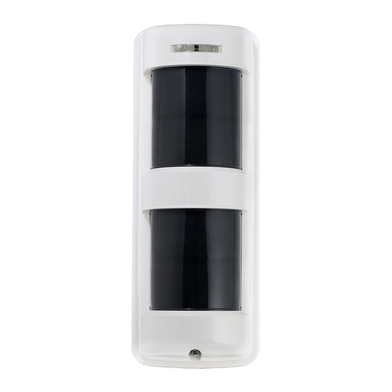
PARTS DESCRIPTION DESCRIPCIÓN DE LAS PIEZAS
Cover
Tapa
A
A
D
Sensor
B
E
C
M
A. Operation LED
LED operacional
B. Lens
Lente
C. Cover locking screw
Tornillo de bloqueo de la tapa
D. Adjustment lever
Palanca de ajuste
E. Sensitivity adjustment
Ajuste de sensibilidad
F. Body locking screw
Tornillo de bloqueo del cuerpo
Accessories
Accesorios
O
P (1 pc, 1 pza.)
TX-114TR/114SR (1 pc, 1 pza.)
TX-114FR (2 pcs, 2 pzas.)
T (2 pcs, 2 pzas.)
TX-114TR/114FR/114SR
DUAL ZONE OUTDOOR PIR / Instruction Manual
TX-114TR
F
G
H
A
I
D
E
J
Body unit + Mounting base
Unidad del cuerpo + Base de montaje
Body unit
Unidad del cuerpo
K
G. Wiring hole
Orificio del cableado
H. Terminals
Terminales
I. Front tamper switch
Interruptor tamper frontal
J. Setting switches
Interruptores de ajuste
K. Space for battery & transmitter
Espacio para la batería y el transmisor
Q TX-114TR/114FR
(2 pcs, 2 pzas.)
S (1 pc, 1 pza.)
U (1 pc, 1 pza.)
TX-114FR
Upper Sensor
Sensor superior
I
J
Lower Sensor
Sensor inferior
Mounting base
Base de montaje
N
O. Area masking sheet
Lámina de enmascaramiento de área
P. Adhesive sheet
Lámina adhesiva
Q. Mounting screw with seal W
R TX-114SR
Tornillo de montaje con sello W
(1 pc, 1 pza.)
R. Mounting screw
Tornillo de montaje
S. Battery holder
Soporte de batería
T. Battery Leads
Cables para la batería
U. Back Tamper killer
Tamper trasero killer
1
TX-114SR
A
Sensor
D
I
E
J
Body unit
Unidad del cuerpo
K
L
L. Wire color
Red
: Battery input (+)
Black : Battery input (-)
Blue
: Alarm signal
Green : Tamper signal
Color del cable
Rojo : Entrada de la batería (+)
Negro : Salida de la batería (-)
Azul
: Señal de alarma
Verde : Señal tamper
M. Back tamper switch
Interruptor tamper trasero
N. Back tamper actuator
Actuador tamper trasero
Advertisement
Table of Contents

Related Manuals for Takex TX-114TR


Summary of Contents for Takex TX-114TR
- Page 1 (1 pc, 1 pza.) (2 pcs, 2 pzas.) R. Mounting screw Tornillo de montaje S (1 pc, 1 pza.) TX-114TR/114SR (1 pc, 1 pza.) S. Battery holder TX-114FR (2 pcs, 2 pzas.) Soporte de batería T. Battery Leads Cables para la batería U.
-
Page 2: Detection Area
PRECAUTIONS PRECAUCIONES Keep installation height 2.6' to 4.0' (0.8 to 1.2m) Mantener la altura de instalación de 2,6' a 4,0' (0,8 a 1,2 m) 2.6'~4.0' (0.8~1.2m) Non detection area Área sin detección DETECTION AREA ZONA DE DETECCIÓN Horizontal Zone PATTERNS OF COVERAGE MODELOS DE COBERTURA Zona horizontal ALARM... - Page 3 TX-114TR/114SR TX-114FR Fine Adjustment Ajuste de precisión (12m) (12m) (12m) (12m) (10m) (10m) (10m) (10m) (5m) (5m) (5m) (5m) 16.5' 16.5' 16.5' 16.5' [TOP VIEW] [TOP VIEW] [VISTA SUPERIOR] [VISTA SUPERIOR] Horizontal Detection Horizontal Detection Detección horizontal Detección horizontal × 2...
- Page 4 £Inserción del cableado [COMMON BATTERY] [BATERÍA COMÚN] [SEPARATE BATTERIES] TX-114TR/114FR Wiring hole [BATERÍAS INDEPENDIENTES] Common for TX-114TR/FR and Transmitter Orificio del cableado Común para TX-114TR/FR y transmisor Each for TX-114TR/FR and Transmitter Adhesive sheet Ambas para TX-114TR/FR y transmisor Lámina adhesiva Battery Batería...
-
Page 5: Installation Instalación
£Montaje en pared £Pole Mounting Utilice la fijación a poste "BP-32" U bracket £Montaje en barra (se vende por separado) TX-114TR/114FR TX-114SR Soporte U Pole mounting brackets Soportes de montaje para barra TX-114SR Use the pole attachment "BP-22". (sold separately) Utilice el acoplamiento de poste "BP-22". -
Page 6: Product Description
•Area setting. The unit issues a tamper signal when its cover is TX-114TR/114SR is equipped with 1set of sensors on Set the area so that the object crosses the area in detached from the unit. the upper side. -
Page 7: Troubleshooting
(4) Remove the body unit. (TX-114TR/114FR only) Solve possible problems according to the following table. If normal operations cannot be TROUBLESHOOTING restored by this means, contact either the dealer from whom you bought the unit or TAKEX. Wall Mounting Trouble... - Page 8 únicamente a modo de guía. de robo. TAKEX no se hace responsable por daños, •Ajuste de área. MODELO DE COBERTURA lesiones o pérdidas ocasionados por accidentes, Considere la dirección probable de desplazamiento...
- Page 9 Salida en tiempo real Funcionamiento •al extraer la tapa de la unidad ALARMA •al extraer la unidad de la pared o barra de instalación. (Únicamente TX-114TR/ TX-114FR) • Forma de interruptor en estado sólido N.O./N.C. Emisión de problema seleccionable Emisión a tiempo real si la unidad sufre problemas funcionales.
-
Page 10: Resolución De Problemas
Resuelva posibles problemas consultando la siguiente tabla. Si tras lo cual no puede restablecer el funcionamiento normal, Los productos TAKEX poseen una garantía de 12 póngase en contacto con el proveedor de adquisición de la unidad o con TAKEX. meses, a partir de la fecha original de compra, contra defectos en el material y la mano de obra. - Page 11 Fax : (+ 44 ) 01256-466268 Tel : 81-75-501-6651 Tel : 408-747-0100 Fax : +61 (03) 9543-2342 Fax : 81-75-593-3816 Fax : 408-734-1100 http : // www. takexeurope. com http : // www. takex-eng. co. jp / http : // www. takex. com No.05-688 1404...