Table of Contents
Advertisement
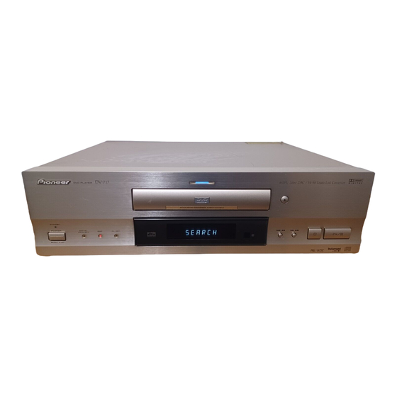
DVD PLAYER
DV-717
THIS MANUAL IS APPLICABLE TO THE FOLLOWING MODEL(S) AND TYPE(S).
Model
Type
DV-717
WY
WY/RD
WY/RE
• Refer to the service guide RRV2004 for DV-515.
CONTENTS
1. SAFETY INFORMATION ...................................... 2
2. EXPLODED VIEWS AND PARTS LIST ................ 3
3. SCHEMATIC DIAGRAM ..................................... 10
4. PCB CONNECTION DIAGRAM .......................... 33
5. PCB PARTS LIST ............................................... 45
6. ADJUSTMENT .................................................... 50
PIONEER ELECTRONIC CORPORATION
PIONEER ELECTRONICS SERVICE, INC. P.O. Box 1760, Long Beach, CA 90801-1760, U.S.A.
PIONEER ELECTRONIC (EUROPE) N.V. Haven 1087, Keetberglaan 1, 9120 Melsele, Belgium
PIONEER ELECTRONICS ASIACENTRE PTE. LTD. 501 Orchard Road, #10-00 Wheelock Place, Singapore 238880
PIONEER ELECTRONIC CORPORATION 1998
STANDBY
STANDBY/ON
DIGITAL
DATA OFF
DNR
FL OFF
Power Requirement
AC220 - 240V
AC220 - 240V
AC220 - 240V
4-1, Meguro 1-Chome, Meguro-ku, Tokyo 153-8654, Japan
0
ACOUSTIC DAMPER MECHANISM
4
1
¡ ¢
7
£¥8
Region restriction code
(region number)
2
4
5
7. GENERAL INFORMATION ................................ 56
7.1 PARTS ......................................................... 56
7.1.1 IC ........................................................... 56
7.2 DISASSEMBLY ........................................... 59
7.3 BLOCK DIAGRAM ....................................... 60
7.4 CIRCUIT DESCRIPTION ............................ 62
T - ZZM OCT. 1998 Printed in Japan
ORDER NO.
RRV2010
Remarks
Advertisement
Table of Contents

Related Manuals for Pioneer DV-717


Summary of Contents for Pioneer DV-717
-
Page 1: Table Of Contents
PIONEER ELECTRONICS SERVICE, INC. P.O. Box 1760, Long Beach, CA 90801-1760, U.S.A. PIONEER ELECTRONIC (EUROPE) N.V. Haven 1087, Keetberglaan 1, 9120 Melsele, Belgium PIONEER ELECTRONICS ASIACENTRE PTE. LTD. 501 Orchard Road, #10-00 Wheelock Place, Singapore 238880 PIONEER ELECTRONIC CORPORATION 1998... -
Page 2: Safety Information
DV-717 1. SAFETY INFORMATION This service manual is intended for qualified service technicians ; it is not meant for the casual do-it- yourselfer. Qualified technicians have the necessary test equipment and tools, and have been trained to properly and safely repair complex products such as those covered by this manual. -
Page 3: Exploded Views And Parts List
DV-717 2. EXPLODED VIEWS AND PARTS LIST NOTES: Parts marked by "NSP" are generally unavailable because they are not in our Master Spare Parts List. mark found on some component parts indicates the importance of the safety factor of the part. -
Page 4: Exterior Section
DV-717 2.2 EXTERIOR SECTION Refer to "2.3 FRONT PANEL SECTION" (1) EXTERIOR SECTION PARTS LIST Mark No. Description Part No. Mark No. Description Part No. Door Plate VAH1312 Tray VNK4333 DVD Plate VAM1077 Clamper VNL1738 Door Panel VNK4324 Bridge VNE2069... -
Page 5: Front Panel Section
DV-717 2.3 FRONT PANEL SECTION 7(4/4) 7(2/4) 7(3/4) 7(1/4) 7(2/4) :Cut position 7(1/4) 8(2/2) 7(3/4) 7(4/4) 8(1/2) :Cut position 8(2/2) 8(1/2) WY/RD Type Only (1) FRONT PANEL SECTION PARTS LIST Mark No. Description Part No. Mark No. Description Part No. -
Page 6: Bottom Section
DV-717 2.4 BOTTOM SECTION Refer to "2.5 LOADING MECHANISM ASSY" 34 (Except WY Type) - Page 7 DV-717 (1) BOTTOM SECTION PARTS LIST Mark No. Description Part No. Mark No. Description Part No. Insulator PNW2766 Screw BBZ30P080FMC Bottom Plate PNA2376 PC Support Cushion VEC2033 Chassis VNA1979 PC Support Spacer VEC2032 PCB Holder PNW2029 PC Support DEC1932 Flat Cable Clip...
-
Page 8: Loading Mechanism Assy
DV-717 2.5 LOADING MECHANISM ASSY • Top View • Bottom View Refer to "2.6 SERVO MECHANISM ASSY" LOADING MECHANISM ASSY PARTS LIST Mark No. Description Part No. Mark No. Description Part No. Loading Motor Assy VXX2505 Servo Mechanism Assy-S VXX2606 DC Motor / 0.3W... - Page 9 DV-717 2.6 SERVO MECHANISM ASSY • Top View SERVO MECHANISM ASSY PARTS LIST Mark No. Description Part No. Mark No. Description Part No. Hook VNL1770 SMEB Assy VWG1968 FFC Holder VNL1802 FGSB Assy VWG2009 Mechanism Base VNL1806 Motor VXM1074 FG Holder...
-
Page 10: Schematic Diagram
DV-717 3. SCHEMATIC DIAGRAM 3.1 OVERALL CONNECTION DIAGRAM, LOMB, LOSB, SMEB and FGSB ASSEMBLIES 1/2, DNRB ASSY SCRB ASSY (VWV1619) (VWV1623) 1/2, AVJB ASSY (VWV1617) CN102 DVDM ASSY (VWS1349) CN602 DILB ASSY (VWG1991) FLKY ASSY PWSB ASSY (VWG1980) (VWG1988) FLKB ASSY... -
Page 11: Power Supply
DV-717 Note : When ordering service parts, be sure to refer to "EXPLODED VIEWS and PARTS LIST" or "PCB PARTS LIST". MSWB ASSY (VWG1996) POWER SUPPLY ASSY (VWR1306) : RF SIGNAL ROUTE PICKUP ASSY : FOCUS SERVO LOOP LINE (VWY1050) - Page 12 DV-717 3.2 FLKY, PWSB and DILB ASSEMBLIES FLKY ASSY (VWG1980)
- Page 13 DV-717 PWSB ASSY (VWG1988) CN602 FLKB ASSY (VWM1860) DILB ASSY (VWG1991) SWITCHES: FLKY ASSY S101: 4/1 S102: 0 S103: ¡/¢ S104: 7 S105: 6...
- Page 14 DV-717 3.3 DVDM ASSY (1/3) (5/6) (2/6) (6/6) (1/6) (3/6) from IC261 (4/6) to IC501 (DVD) ADC1175CIJMX (DVD) (DVD) to IC501 to IC701 (CD) to CN120 (CD) IC501 to IC501...
- Page 15 DV-717 from Q107,Q108 DVDM ASSY(1/3) (VWS1349) to IC101 IC507 TC74VHCT245AFT to IC101 (1/2) (2/2) to IC601 to IC701 (CD) (CD) (CD) (CD) to IC302 : RF SIGNAL ROUTE LEVEL SHIFT : ROM DATA SIGNAL ROUTE : FOCUS SERVO LOOP LINE...
- Page 16 DV-717 3.4 DVDM ASSY (2/3) DVDM ASSY(2/3) (VWS1349) XCSDOLV,XCS6,XWRL,XWRH,XLT3, XAMUTE,XDACK1,XDREQ1,IR,SEL-IR, 48/44,XDVRST1,XAVIRQ0,NSP-SW, SSCK,SSO,XRESET VYW1518 ADDRESS A2–A10 DATA IC605(1/2) TC74VHC139FT IC605(2/2) TC74VHC139FT...
-
Page 17: Audio Signal Route
DV-717 : AUDIO SIGNAL ROUTE : ROM DATA SIGNAL ROUTE from IC801 from IC701 IC703 TC74VHCT541AFT (DVD) SDATA from IC301 (DVD) (DVD) MONITOR OUTPUT from IC301 SERVO to IC801 CN101 to IC801 from IC201... - Page 18 DV-717 3.5 DVDM ASSY (3/3) IC810(1/4) TC74VHC00FT IC810(2/4) TC74VHC00FT IC810(3/4) TC74VHC00FT IC810(4/4) TC74VHC00FT (DVD) IC801 MB86371C from IC701 from IC701 from IC701...
- Page 19 DV-717 IC906(1/3) for IC801 IC906(3/3) IC906 : CLOCK GENERATOR SECTION TC7W04F DVDM ASSY(3/3) IC906(2/3) (VWS1349) for IC801 IC904(1/3) IC904(2/3) IC904 : for IC701 TC7W04F for IC201 IC904(3/3) CN101 : AUDIO SIGNAL ROUTE : ROM DATA SIGNAL ROUTE (V/CB) : V/CB SIGNAL ROUTE...
- Page 20 DV-717 • WAVEFORMS OF DVDM ASSY Note : No. in the table correspond to the number on the schematic diagram. Measurement condition : No. 1 to 4 and 6 to 11 : Disc MJK1, Title 1-chp 1 No. 5 : CD, ABEX-784 Track 1 No.
- Page 21 DV-717...
- Page 22 DV-717 3.6 AVJB ASSY (1/2) CN9020...
- Page 23 DV-717 : AUDIO SIGNAL ROUTE AVJB ASSY(1/2) (VWV1617)
- Page 24 DV-717 3.7 AVJB ASSY (2/2) AVJB ASSY(2/2) (VWV1617) CN9031...
-
Page 25: V/Cb) : V/Cb Signal Route
DV-717 (V/CB) : V/CB SIGNAL ROUTE : Y SIGNAL ROUTE : C SIGNAL ROUTE CN1001... - Page 26 DV-717 3.8 DNRB ASSY (1/2) CONNECTOR...
- Page 27 DV-717 : R SIGNAL ROUTE : G SIGNAL ROUTE : B SIGNAL ROUTE DNRB ASSY(1/2) : Y SIGNAL ROUTE (VWV1619) : C SIGNAL ROUTE...
- Page 28 DV-717 3.9 DNRB ASSY (2/2) DNRB ASSY(2/2) (VWV1619) B LEVEL ADJ. G LEVEL ADJ. Y LEVEL ADJ. C LEVEL ADJ.
- Page 29 DV-717 : R SIGNAL ROUTE : G SIGNAL ROUTE : B SIGNAL ROUTE : Y SIGNAL ROUTE : C SIGNAL ROUTE R LEVEL ADJ.
- Page 30 DV-717 3.10 SCRB ASSY SCRB ASSY (VWV1623) CN103...
- Page 31 DV-717 UPPER BELLOW...
- Page 32 DV-717 3.11 POWER SUPPLY ASSY and MSWB ASSY CN110...
-
Page 33: Pcb Connection Diagram
DV-717 4. PCB CONNECTION DIAGRAM NOTE FOR PCB DIAGRAMS : 1. Part numbers in PCB diagrams match those in the schematic 3. The parts mounted on this PCB include all necessary parts for diagrams. several destinations. 2. A comparison between the main parts of PCB and schematic For further information for respective destinations, be sure to diagrams is shown below. - Page 34 DV-717 4.2 FLKY, PWSB and DIRB ASSEMBLIES PWSB ASSY IC102 DIRB ASSY FLKY ASSY...
-
Page 35: Flky Assy
DV-717 DIRB ASSY SIDE A FLKY ASSY CN602 (VNP1656-B) IC102 Q101 PWSB ASSY SIDE B Q203 Q202 Q201 (VNP1656-B) IC101 Q102 E F G... -
Page 36: Dvdm Assy
DV-717 4.3 DVDM ASSY • This PCB is a four-layered board. Middle layer is mainly connected to Vcc and GND. CN102 CN101 DVDM ASSY Q604 IC881 Q881 Q603 VC901 IC904 IC804 Q801 Q914 Q802 IC603 VR801 IC801 IC602 IC803 CN101... - Page 37 DV-717 • This PCB is a four-layered board. Middle layer is mainly connected to Vcc and GND. DVDM ASSY Q601 Q602 IC906 Q872 Q862 Q852 IC901 IC903 IC605 Q871 Q861 Q851 IC601 IC806 IC810 IC807 IC805 Q803 IC809 IC808 IC802...
- Page 38 DV-717 4.4 AVJB ASSY AVJB ASSY IC402 Q821 Q801 IC841 IC401 IC301 Q753 Q941 Q771 Q772 Q831 IC831 IC801 IC821 IC202 IC201 Q752 IC102 IC822 IC802...
- Page 39 DV-717 SIDE A CN9031 CN9020 (VNP1658-A) Q711 Q722 Q721 IC601 IC602 C102...
- Page 40 DV-717 AVJB ASSY Q901 Q902 IC702 IC604 Q921 IC704...
- Page 41 DV-717 SIDE B C604 Q921 Q923 Q922 Q504 Q503 Q802 Q803 IC501 Q832 Q833 IC602 Q501 Q502 IC704 IC706 D2001 D2002 (VNP1658-A)
- Page 42 DV-717 4.5 DNRB ASSY IC104 IC103 SIDE A DNRB ASSY (VNP1655-A) CN802 SIDE B DNRB ASSY (VNP1655-A) VR504 VR505 VR508 VR507 VR501-503 Q652 Q651 IC101 Q602 Q601 IC102 Q612 Q611 Q622 Q621...
-
Page 43: Scrb Assy
DV-717 4.6 SCRB ASSY SCRB ASSY SIDE A CN103 (VNP1658-A) Q1225 SCRB ASSY SIDE B (VNP1658-A) Q1001 Q1201 Q1202 Q1205 Q1222 Q1203 Q1204... - Page 44 DV-717 4.7 POWER SUPPLY and MSWB ASSEMBLIES SIDE A POWER SUPPLY ASSY CN110 IC102 IC103 IC201 IC51 MSWB ASSY AC IN (VNP1658-A)
-
Page 45: Pcb Parts List
DV-717 5. PCB PARTS LIST NOTES: Parts marked by "NSP" are generally unavailable because they are not in our Master Spare Parts List. mark found on some component parts indicates the importance of the safety factor of the part. Therefore, when replacing, be sure to use parts of identical designation. - Page 46 DV-717 Mark No. Description Part No. Mark No. Description Part No. IC504 TC74HC573AF OTHERS IC303 TC74HCU04AF CN102 CONNECTOR 7P 07P-FJ REMOTE RECEIVER UNIT GP1U28X IC807, IC808 TC74LCX245FT J101 CONNECTOR ASSY PF02NN2D12 IC810 TC74VHC00FT V101 FL TUBE VAW1046 IC506, IC605 TC74VHC139FT...
- Page 47 DV-717 Mark No. Description Part No. Mark No. Description Part No. R607–R611, R723 (47Ω) DCN1090 C324 CCSRCH470J50 R505, R506, R615, R616, R620 (10kΩ) DCN1094 C117, C122 CCSRCH471J50 R692, R708, R709, R733, R734 (10kΩ) DCN1094 C128, C309 CCSRCH560J50 R740, R741, R748, R749 (10kΩ)
- Page 48 DV-717 Mark No. Description Part No. Mark No. Description Part No. IC812 NJM79M08FA IC301 PD0236AM C907 CEAT470M10 IC201 PD2058A C404, C419, C817 CEAT470M16 C501, C511, C521, C531 CEAT471M10 IC401, IC402 PE8001A C824, C825 CEAT471M16 IC202 TC4W53F C851 CEAT471M6R3 IC102 TC74HCT7007AF...
- Page 49 DV-717 Mark No. Description Part No. Mark No. Description Part No. CN102, CN103 22P CONNECTOR VKN1253 SCRB ASSY CN101 26P CONNECTOR VKN1257 SCREW PLATE VNE1948 SEMICONDUCTORS KN1–KN3 EARTH METAL FITTING VNF1084 Q1204 2PB709A X201 CERAMIC RESONATOR(24MHz) VSS1118 Q1001, Q1201, Q1203, Q1205...
-
Page 50: Adjustment
DV-717 6. ADJUSTMENT 6.1 ADJUSTMENT ITEMS AND LOCATION Adjustment Items Adjustment Points (PCB Part) DVDM ASSY [Electrical Part] 1 16MHz Master Clock Adjustment SIDE A CN9031 CN9020 2 VCO Offset Adjustment 3 Y Level Adjustment VC901 4 C Level Adjustment... -
Page 51: Jigs And Measuring Instruments
DV-717 6.2 JIGS AND MEASURING INSTRUMENTS Dual-trace oscilloscope (with delay) Screwdriver(small) Frequency band 40MHz Screwdriver(small) DVD test disc (DVD-MJK1) Frequency counter Display digit 8-digit TV monitor 6.3 NECESSARY ADJUSTMENT POINTS When Adjustment Points EXCHANGE PCB ASSY Mechanical Exchange board point... -
Page 52: Electrical Adjustment
DV-717 6.4 ELECTRICAL ADJUSTMENT 16MHz Master Clock Adjustment DVDM ASSY • Normal mode • Power ON 16.934400MHz ± 80Hz VC901 Player START DVDM ASSY IC904 Frequency counter VCO Offset Adjustment 1.9V± 0.1V DVDM ASSY • Normal mode • Play the DVD test disc... - Page 53 DV-717 Y Level Adjustment • Normal mode • Play the DVD test disc DNRB 1Vp-p ASSY at the composite signal part VR505 VIDEO Player (Rear) START TV monitor Oscilloscope Probe (10:1) V: 20mV/div. H: 10µsec/div. AC mode VIDEO C Level Adjustment •...
- Page 54 DV-717 R Level Adjustment • Normal mode • Play the DVD test disc DNRB 0.7Vp-p ASSY at the 100% color-bar signal part VR503 EURO CONNECTOR R OUT Player (Rear) START TV monitor Oscilloscope Probe (10:1) V: 20mV/div. H: 10µsec/div. AC mode...
- Page 55 DV-717 B Level Adjustment • Normal mode • Play the DVD test disc DNRB 0.7Vp-p ASSY at the 100% color-bar signal part VR501 EURO CONNECTOR B OUT Player (Rear) START TV monitor Oscilloscope Probe (10:1) V: 20mV/div. H: 10µsec/div. AC mode...
-
Page 56: General Information
DV-717 7. GENERAL INFORMATION 7.1 PARTS 7.1.1 IC • The information shown in the list is basic information and may not correspond exactly to that shown in the schematic diagrams. • List of IC PE5018B, PE5012A, PD3381A 7 PE5018B (FLKY ASSY : IC101) •... - Page 57 DV-717 PE5012A (DVDM ASSY : IC501) • Mechanism Control IC • Pin Function e l l " t " L " " L x i f " " L " " L " " L − − − l l i −...
- Page 58 DV-717 PD3381A (DVDM ASSY : IC601) • System Control IC • Pin Function − l a i − l e l l l o − − − − − − − − − − − − − c t i −...
-
Page 59: Disassembly
DV-717 7.2 DISASSEMBLY BONNET DVDM ASSY Be careful of the flexible cable. DISC TRAY This flexible replace with a service parts POWER OPEN/CLOSE VDA1712. DVDM ASSY DVDM ASSY... -
Page 60: Block Diagram
DV-717 7.3 BLOCK DIAGRAM... - Page 61 DV-717...
-
Page 62: Circuit Description
DV-717 7.4 CIRCUIT DESCRIPTION 7.4.1 VIDEO SIGNAL PROCESSING BLOCK 7 CXD1854Q Block The major processing functions of the CXD1854Q block are: (1) Field-correlative cyclic digital noise reduction (2) Block noise reduction (3) Horizontal contour compression These functions are performed for the Y signal and not performed for the C signal. -
Page 63: Panel Facilities And Specifications
DV-717 8. PANEL FACILITIES AND SPECIFICATIONS 7 Front panel 7 Rear panel... -
Page 64: Remote Control
DV-717 7 Remote control 7 Display window Indicates location for Last Indicates that playback Indicates GUI operation is Memory is being recorded settings (condition) have being performed. been memorized. in memory. This lights during play of a Indicates Multi-Angle disc with a sampling playback is in progress. -
Page 65: Specifications
DV-717 SPECIFICATIONS "Dolby, Digital (AC-3)" and the double-D symbol are trademarks of Dolby Laboratories Licensing Corporation. Accessories Remote control unit (VXX2601) Audio cord (VDE1033) (CU-DV025) (L=1.5m) White Video cord (VDE1048) (L=1.5m) Other included items : • Warranty card (With region No."2"...