Table of Contents
Advertisement
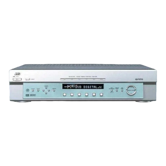
HOME CINEMA CONTROL CENTER
RX-E111RSL / RX-E112RSL
AUDIO
DVD
STB
VCR
TV
SLEEP
TV DIRECT
DVD
STB
VCR
TV
ANALOG/DIGITAL
TAPE
FM
AM
INPUT
+
SOUND
BASS
+
–
CENTER
1
2
3
–
–
+
BASS
REAR-L
TEST
4
5
6
+
–
+
BASS BOOST
TREBLE
REAR-R
7
8
9
–
–
+
EFFECT
TREBLE
SUBWOOFER
10
0
+10
RETURN
FM MODE
+100
TA/NEWS/INFO
SURROUND
RDS
ON/OFF
DVD
MENU
PTY(
ENTER
PTY9
SURROUND
DISPLAY MODE
MODE
DVD MENU
PTY SEARCH
TV VOL
CHANNEL
VOLUME
VCR
TV/VIDEO
DIMMER
MUTING
CONTROL
/REW
PLAY
FF/
DOWN
TUNING
UP
REC
STOP
PAUSE
RM-SRXE111R
REMOTE CONTROL
HOME CINEMA CONTROL CENTER
STANDBY
TV DIRECT
STANDBY/ON
CONTROL
PHONES
ADJUST
MEMORY
SETTING
INSTRUCTIONS
HOME CINEMA CONTROL CENTER
DVD
STB
VCR
TV
TAPE
FM/AM
ANALOG
L
C
R
PL ΙΙ
SLEEP
AUTO
MODE
TA
NEWS
INFO
RDS
TUNED
ST
AUTO MUTING
LPCM
DSP HP
SUBWFR LFE
MH
Z
INPUT
DOLBY D
AUTO SR
KH
Z
LS
S
RS
VOL
DTS
INPUT ATT
ANALOG/DIGITAL
DVD
STB
VCR
TV
TAPE
FM/AM
INPUT ATT
For Customer Use:
SURROUND
SURROUND
ON/OFF
MODE
MASTER VOLUME
Enter below the Model No. and Serial
No. which are located either on the rear,
bottom or side of the cabinet. Retain this
information for future reference.
Model No.
Serial No.
LVT0858-001A
[B]
Advertisement
Table of Contents

Related Manuals for JVC LVT0858-001A


Summary of Contents for JVC LVT0858-001A
- Page 1 ANALOG/DIGITAL MASTER VOLUME INPUT ATT For Customer Use: Enter below the Model No. and Serial No. which are located either on the rear, bottom or side of the cabinet. Retain this information for future reference. Model No. Serial No. LVT0858-001A...
- Page 2 Warnings, Cautions and Others IMPORTANT for the U.K. DO NOT cut off the mains plug from this equipment. If the plug fitted is not suitable for the power points in your home or the cable is too short to reach a power point, then obtain an appropriate safety approved extension lead or consult your dealer.
- Page 3 CAUTION • Do not block the ventilation openings or holes. (If the ventilation openings or holes are blocked by a newspaper or cloth, etc., the heat may not be able to get out.) • Do not place any naked flame sources, such as lighted candles, on the apparatus.
- Page 4 “SOME DOS AND DON’TS ON THE SAFE USE OF EQUIPMENT” This equipment has been designed and manufactured to meet international safety standards but, like any electrical equipment, care must be taken if you are to obtain the best results and safety is to be assured. Do read the operating instructions before you attempt to use the equipment.
-
Page 5: Table Of Contents
Table of Contents Parts Identification ... 2 Getting Started ... 3 Before Installation ... 3 Checking the Supplied Accessories ... 3 Putting Batteries in the Remote Control ... 3 Connecting the FM and AM (MW/LW) Antennas ... 4 Connecting the Speakers ... 5 Connecting Audio/Video Components ... -
Page 6: Parts Identification
Parts Identification Front Panel STANDBY TV DIRECT STANDBY/ON CONTROL PHONES SETTING ADJUST 6 7 8 Remote Control AUDIO SLEEP TV DIRECT ANALOG/DIGITAL TAPE INPUT – SOUND BASS CENTER – – BASS REAR•L TEST – BASS BOOST TREBLE REAR•R – – EFFECT TREBLE SUBWOOFER... -
Page 7: Getting Started
Getting Started Before Installation General Precautions • DO NOT insert any metal object into the unit. • DO NOT disassemble the unit or remove screws, covers, or cabinet. • DO NOT expose the unit to rain or moisture. Locations • Install the unit in a location that is level and protected from moisture. -
Page 8: Connecting The Fm And Am (Mw/Lw) Antennas
Getting Started Connecting the FM and AM (MW/LW) Antennas AM (MW/LW) Loop Antenna (supplied) Snap the tabs on the loop into the slots of the base to assemble the AM (MW/LW) loop antenna. If AM (MW/LW) reception is poor, connect an outdoor single vinyl-covered wire (not supplied). -
Page 9: Connecting The Speakers
AM (MW/LW) antenna connection Connect the AM (MW/LW) loop antenna supplied to the AM LOOP terminals. Turn the loop until you have the best reception. • If the reception is poor, connect an outdoor single vinyl-covered wire to the AM EXT terminal. Keep the AM (MW/LW) loop antenna connected. - Page 10 Getting Started Speaker Layout Diagram “YES” for the subwoofer and “SML” for the front, center and rear speakers are initial settings. To get best possible sound, change the subwoofer and speaker settings to fit your listening conditions. (See page 15.) Center speaker Left front speaker...
-
Page 11: Connecting Audio/Video Components
Connecting Audio/Video Components Turn off all components before connections. Audio cords and optical digital cords are not supplied with this unit. Use the cords supplied for the other components or purchase them at an audio or electric appliance store. Digital coaxial cord (supplied 1 cable) Digital optical cord (not supplied) Digital connections DIGITAL IN... - Page 12 Getting Started Turn off all components before connections. RX-E111R/ RX-E112R SCART Terminal Specifications AUDIO Composite − VIDEO S-video − AUDIO Composite VIDEO S-video T-V LINK Illustrations of the input/output terminals below are typical examples. When you connect other components, refer also to their manuals since the terminal names actually printed on the rear vary among the components.
-
Page 13: Connecting The Power Cord
For details on T-V LINK, refer also to the manuals supplied with the TV and the VCR. • Connect SCART cable to EXT-2 terminal on your JVC’s T-V LINK compatible TV for T-V LINK function. • Some TV, VCR, STB and DVD player support this type of data communication. -
Page 14: Basic Operations
Basic Operations This manual mainly explains operations using the buttons and controls on the front panel. You can also use the buttons on the remote control if they have the similar names (or marks) as those on the front panel. If operations using the remote control are different from those using the front panel, they are then explained. -
Page 15: Activating Tv Direct
CAUTION: Be sure to turn down the volume: • Before connecting or putting on headphones, as high volume can damage both the headphones and your hearing. • Before removing headphones, as high volume may output from the speakers. Activating TV Direct TV Direct enables you to use this unit as an AV selector while the unit is not turned on. -
Page 16: Turning Off The Sounds Temporarily-Muting
Basic Operations AUDIO SLEEP SLEEP ANALOG/DIGITAL TAPE INPUT – SOUND SOUND BASS CENTER – – BASS REAR•L TEST – BASS BOOST TREBLE REAR•R – – EFFECT TREBLE SUBWOOFER RETURN FM MODE TA/NEWS/INFO SURROUND ON/OFF ENTER PTY( SURROUND MODE DVD MENU PTY SEARCH TV VOL CHANNEL... -
Page 17: Basic Settings
Basic Settings CONTROL 5/∞/3/2 STANDBY TV DIRECT STANDBY/ON CONTROL SETTING ADJUST PHONES SETTING Setting the Digital Input (DIGITAL IN) Terminals When you use the digital input terminals, register what components are connected to which terminals (DIGITAL IN 1/2) so that the correct source name will appear when you select the digital source. - Page 18 Basic Settings CONTROL 5/∞/3/2 STANDBY TV DIRECT STANDBY/ON CONTROL ADJUST PHONES SETTING SETTING DGTL AUTO : Select this for the digital input mode. The unit automatically detects the incoming signal format, then the digital signal indicator for the detected signals lights up. ANALOGUE : Select this for the analogue input mode.
-
Page 19: Setting The Subwoofer Information
“YES” for the subwoofer and “SML” for the front, center and rear speakers are initial settings. To get best possible sound, change the subwoofer and speaker settings to fit your listening conditions. Setting the Subwoofer Information Register whether you have connected a subwoofer or not. If you have already connected a subwoofer, follow the procedure below. - Page 20 Basic Settings CONTROL 5/∞/3/2 STANDBY TV DIRECT STANDBY/ON CONTROL SETTING ADJUST PHONES SETTING Speaker Distance—FRNT D, CNTR D, REAR D The distance from your listening point to the speakers is another important element to obtain the best possible surround sound of the Surround and DSP modes.
- Page 21 Crossover Frequency—CROSS Small speakers cannot reproduce the bass sounds efficiently. If you use a small speaker in any position, this unit automatically reallocates the bass sound elements assigned to the small speaker to the large speakers. To use this function properly, set this crossover frequency level according to the size of the small speaker connected.
-
Page 22: Setting Auto Surround
Basic Settings CONTROL 5/∞/3/2 STANDBY TV DIRECT STANDBY/ON CONTROL SETTING ADJUST PHONES SETTING Press CONTROL∞ (or 5) repeatedly until “D.COMP (Dynamic Range Compression)” (with the current setting) appears on the display. CONTROL Ι * “MID” is the initial setting. If you have already changed the setting, another setting will be shown. -
Page 23: Setting The Auto Function Mode
: The AUTO SR indicator lights up on the display. • If multichannel signals come in, an appropriate Surround mode will be turned on. • If Dolby Digital 2ch or DTS 2ch signals including surround signals come in, “PL II MOVIE” will be selected. -
Page 24: Sound Adjustments
Sound Adjustments You can also use the remote control for some sound adjustments. • When using the remote control, see also “Mastering Remote Operations” on page 38. CONTROL 5/∞/3/2 STANDBY TV DIRECT STANDBY/ON CONTROL SETTING ADJUST PHONES ADJUST Attenuating the Input Signal When the input level of the analogue source is too high, the sounds will be distorted. -
Page 25: Reinforcing The Bass
Reinforcing the Bass You can boost the bass level—Bass Boost. • You have to make these adjustments for each source. Before you start, remember... There is a time limit in doing the following steps. If the setting is canceled before you finish, start from step 1 again. Press ADJUST. -
Page 26: Adjusting The Subwoofer Output Level
Sound Adjustments CONTROL 5/∞/3/2 STANDBY TV DIRECT STANDBY/ON SETTING ADJUST PHONES ADJUST Adjusting the Subwoofer Output Level You can adjust the subwoofer output level if you have connected a subwoofer and set the subwoofer information correctly—“YES” (see page 15). • You have to make this adjustment for each source. Before you start, remember... -
Page 27: Tuner Operations
Tuner Operations You can also use the remote control for some tuner operations. • When using the remote control, see also “Mastering Remote Operations” on page 38. CONTROL 5/∞/3/2 STANDBY TV DIRECT STANDBY/ON CONTROL ADJUST PHONES SETTING Tuning into Stations Manually Press FM/AM to select the band. -
Page 28: Using Preset Tuning
Tuner Operations CONTROL 5/∞/3/2 STANDBY TV DIRECT STANDBY/ON CONTROL SETTING ADJUST PHONES Using Preset Tuning Once a station is assigned to a channel number, the station can be quickly tuned. You can preset up to 30 FM and 15 AM (MW/LW) stations. -
Page 29: Selecting The Fm Reception Mode
To tune in a preset station Press FM/AM to select the band. The last received station of the selected band is tuned in, and the CONTROL buttons now work for tuner operations. FM/AM Ex.: When selecting the FM band. Press CONTROL ∞ (or 5) repeatedly until “<... -
Page 30: Using The Rds (Radio Data System) To Receive Fm Stations
Tuner Operations You need to set RDS/DVD MENU selector to “RDS,” when you want to operate RDS. AUDIO SLEEP TV DIRECT ANALOG/DIGITAL TAPE INPUT – BASS CENTER SOUND – – TEST BASS REAR•L – BASS BOOST TREBLE REAR•R – – EFFECT TREBLE SUBWOOFER... -
Page 31: Searching For A Program By Pty Codes
Searching for a Program by PTY Codes One of the advantages of the RDS service is that you can locate a particular kind of program from the preset channels (see page 24) by specifying the PTY codes. To search for a program using the PTY codes Before you start, remember... - Page 32 Tuner Operations You need to set RDS/DVD MENU selector to “RDS,” when you want to operate RDS. AUDIO SLEEP TV DIRECT ANALOG/DIGITAL TAPE INPUT – BASS CENTER SOUND – – BASS REAR•L TEST – BASS BOOST TREBLE REAR•R – – EFFECT TREBLE SUBWOOFER...
-
Page 33: Switching To Broadcast Program Of Your Choice Temporarily
Switching to Broadcast Program of Your Choice Temporarily Another convenient RDS service is called “Enhanced Other Network.” This allows the unit to switch temporarily to a broadcast program of your choice (TA, NEWS, and/or INFO) from a different station except in the following cases: •... -
Page 34: Creating Realistic Sound Fields
Creating Realistic Sound Fields You can use the following Surround modes to reproduce a realistic sound field: I Dolby Surround • Dolby Pro Logic II • Dolby Digital I DTS Digital Surround I DAP (Digital Acoustic Processor) modes I All Channel Stereo I Dolby Surround Dolby Pro Logic II* Dolby Pro Logic II has newly developed multichannel playback... -
Page 35: All Channel Stereo
I DAP (Digital Acoustic Processor) modes DAP modes have been designed to create important acoustic surround elements. The sound heard in a live club, dance club, hall or pavilion consists of direct sound and indirect sound—early reflections and reflections from behind. Direct sounds reach the listener directly without any reflection. -
Page 36: About Relations Between Speaker Layout And Surround Modes
Creating Realistic Sound Fields About Relations between Speaker Layout and Surround Modes Available Surround modes will vary depending on how many speakers are used with this unit. Make sure that you have set the speaker information correctly (see page 15). •... -
Page 37: Using Dolby Pro Logic Ii, Dolby Digital And Dts Digital Surround (Remote Control)
It will be convenient for you to use the remote control for Surround adjustments, since you can make adjustments from your listening point, and use the test signal. • When using the buttons on the front panel, see pages 36 and 37. - Page 38 Creating Realistic Sound Fields AUDIO SLEEP TV DIRECT ANALOG/DIGITAL TAPE INPUT – SOUND SOUND BASS CENTER SOUND – – BASS REAR•L TEST TEST – BASS BOOST TREBLE REAR•R – – EFFECT TREBLE SUBWOOFER EFFECT RETURN FM MODE 100+ TA/NEWS/INFO SURROUND SURROUND ON/OFF ON/OFF...
-
Page 39: Using Dap Modes And All Channel Stereo (Remote Control)
Using DAP Modes and All Channel Stereo (Remote Control) Once you have adjusted the DAP modes and All Channel Stereo, the adjustment is memorized for each source. • You cannot use the DAP modes and All Channel Stereo if no rear speakers are connected. -
Page 40: Using Dolby Pro Logic Ii, Dolby Digital And Dts Digital Surround (Front Panel)
Creating Realistic Sound Fields CONTROL 5/∞/3/2 STANDBY TV DIRECT STANDBY/ON CONTROL SETTING ADJUST PHONES ADJUST Before you start, remember... • Make sure that you have set the speaker information correctly (see page 15). • You cannot adjust the center speaker output level when you have set “CNTR SP”... -
Page 41: Using Dap Modes And All Channel Stereo (Front Panel)
Press CONTROL 3 (or 2) to make adjustments. • When adjusting the speaker output levels, make adjustments so that the sound level of the selected speaker is set at the same level as that of the front speakers. CONTROL PR ΙΙ ANALOG LPCM SUBWFR LFE... -
Page 42: Mastering Remote Operations
Mastering Remote Operations You can use the remote control to operate not only this unit but also other JVC’s products. • Refer also to the manuals supplied for the other products. – This remote control can operate a VCR whose remote control code is set to A. - Page 43 26 – 29). DISPLAY MODE +100 PTY SEARCH/PTY+/– : Search for PTY codes. TA/NEWS/INFO Operating other JVC’s products ❏ Turning on the power—POWER buttons ❏ Selecting the channels—10 keys PAUSE I After pressing TV (source selecting button), you can use the 10 keys for selecting a channel on the TV.
- Page 44 I These buttons work only for TV operations. TV/VIDEO TV/VIDEO TV VOL +/– TV VOL ❏ Operating DVD menu for JVC’s DVD player PTY( PTY SEARCH PAUSE I After setting RDS/DVD MENU selector to “DVD MENU,” you can use the buttons illustrated above for DVD menu operations.
- Page 45 Operating other Manufacturers’ Equipment By changing the transmittable signals, you can use the remote control supplied for this unit to operate other manufacturers’ equipment. • Refer also to the manuals supplied for the other products. • To operate those components with the remote control, first you need to set the manufacturers’...
- Page 46 Mastering Remote Operations ❏ Changing the transmittable signals for operating a 1 Press and hold VCR 2 Press VCR. 3 Enter manufacturer’s code using buttons 1 – 9, and 0. 4 Release VCR Now, you can perform the following operations on the VCR. : Turn on or off the VCR.
-
Page 47: Troubleshooting
Troubleshooting Use this chart to help you solve daily operational problems. If there are any problems you cannot solve, contact your JVC’s service center. PROBLEM The power does not come on. No sound from speakers. Buttons cannot be used. Sound from one speaker only. - Page 48 Troubleshooting PROBLEM The STANDBY lamp lights up after turning on the power, but soon the unit turns off (into standby mode). Remote control does not operate as you intend. Remote control does not work. Note: When you use the digital coaxial connection, the sounds may be intermitted by the outside noise such as a lightning discharge but they will restore automatically.
-
Page 49: Specifications
Specifications Amplifier Output Power Audio Audio Input Sensitivity/Impedance (1 kHz): Audio Input (DIGITAL IN)* : Audio Output Level: Signal-to-Noise Ratio (’66 IHF/DIN): Frequency Response (8 Ω): Tone Control: Bass Boost: Video Video Input Sensitivity/Impedance (1 kHz): Composite video: S-VIDEO: Video Output Level/Impedance (1 kHz): Composite video: S-VIDEO: Signal-to-Noise Ratio (S/N):... - Page 50 Specifications FM tuner (IHF) Tuning Range: Usable Sensitivity: 50 dB Quieting Sensitivity: Signal-to-Noise Ratio (IHF-A weighted): Total Harmonic Distortion: Stereo Separation at REC OUT: Alternate Channel Selectivity: AM (MW/LW) tuner Tuning Range: Usable Sensitivity: Signal-to-Noise Ratio: General Power Requirements: Power Consumption: Dimensions (W x H x D): 87.50 MHz to 108.00 MHz 17.0 dBf (1.95 µV/75 Ω)
- Page 51 VICTOR COMPANY OF JAPAN, LIMITED 0102NHMMDWJEIN...