Table of Contents
Advertisement
Advertisement
Table of Contents

Related Manuals for VESPA 1962 150


Summary of Contents for VESPA 1962 150
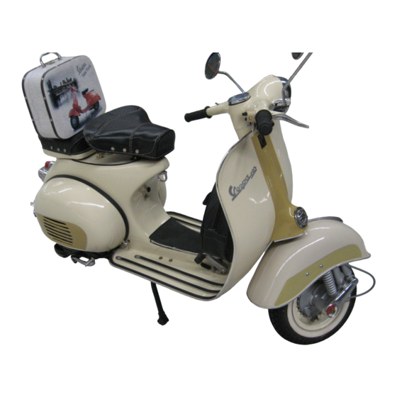
- Page 2 STABILIMENTO DI PONTEDERA UFFICIO TECNICO SERIE Dis. 88356 M 2 a EDIZIONE, 600016102 Printed in Italy Fig. 1 – Vespa 150...
-
Page 3: Table Of Contents
NOTICE To keep your VESPA in perfect running order and not to invalidate the guarantee offered by the contract, it is advisable to entrust repairs only to retailers or authorized service stations. Demand original Piaggio spare parts exclusively. All PIAGGIO spares are made of the same material, have undergone the same machining steps and inspections as the components of your VESPA. - Page 4 For its characteristics (comfort, low fuel consumption, noiseless running, neatness etc.) the Vespa can have a large field of use: for work purpose as well as tourist trips, both along large highways and narrow farm roads.
-
Page 5: Technical Data
TECHNICAL DATA Fig. 2 & 3: - Stamping on frame (1) – Stamping on engine (2) -
Page 6: Identification Data
Fuel consumption (CUNA Standards) 2.2 liters to 100 Km (107 miles per USA gal ; 128 miles per imp. gal). Max speed (CUNA) 85 Km "h (53 m.p.h. ) Carrying capacity 2 persons and 10 Kg. (22 Ibs) of luggage. Range 360 Km (225 miles) Wheel base... - Page 7 1. Ignition coil in flywheel magneto - 2. External H. T. coil - 3. Rotor cam - 4. Breaker - 5. Condenser - 6. Sparkplug - 7. Engine cut-out on switch. Such numbers and prefixes identify the Vespa as prescribed by law and are repeated on the test card and other documents of the Vespa. They must be quoted when ordering...
- Page 8 ENGINE Single horizontal cylinder, two-stroke, with deflector piston and rotary valve, i. e.: fuel mixture flow to the cylinder is controlled by the rotation of a crankweb (see Fig. 4). The engine works on a 2% gasoline-oil mixture. Bore 57 mm (2.24") Stroke 57 mm (2.24") Displacement...
- Page 9 Fig. 6 - Feeding circuit 1. Fuel cock lever with sediment trap: A) Reserve, B) Open, C) Closed - 2. Float - 3. Air cleaner with carburettor - 4. Air vent for starter device - 5. Set screw for throttle slide - 6. Throttle slide - 7. Air vent for main jet - 8.
- Page 10 with that of the clutch, on left hand side of handlebars (see Fig. 8). Starting. By means of kick-starter, night hand side of scooter. The multiple gear and consequently the engine is set in motion through a ratchet sector and a gear by operating the kick-starter.
-
Page 11: Frame
Fig. 8 VESPA controls 1. Gear change twistgrip with clutch control lever - 2. Front brake lever - 3. Throttle control grip - 4. Light and dip switch - 5. Front brake shoes - 6. Rear brake pedal - 7. Kick-starter - 8. Gear shifter - 9. - Page 12 Steering column, suspension and wheels. The steering column bears the handlebars, clamped on its top end, and the front wheel swinging hub, pivoted at its bottom end through a stub axle (see Fig. 9). Front suspension with variable rate coil spring and double action hydraulic damper. Rear suspension: swinging bracket for engine and rear wheel, variable rate coil spring and coaxial, double action hydraulic tamper.
- Page 13 Steering lock. A suitable security lock is arranged on the frame, near the handlebars. Turning the key anticlockwise and the handlebars to the left, the lock engages the lugs welded on the steering column, so that the machine can only turn around. Turn the key clockwise for releasing the steering system (see Fig.
- Page 14 Fig. 11 – Handlebar switch A – Engine cut-out B. Parking lights and speedometer bulb on – C. Lights off – D. Head lamp, tail lamp speedometer bulb on – E. Dip switch – F. Horn button - 7. Main switch Fig.
-
Page 15: Electric Wiring
Fig. 12 – Electric wiring diagram 1. Flywheel magneto - 2. External ignition coil - 3. Sparkplug - 4. Low tension terminal - 5. Tail lamp 16V-3W - (. STOP light - 6V-3W) - 7. Main switch - 8. Speedometer bulb (6V-0.6W) - 9. Double filament bulb (6V25/25W) - 10. -
Page 16: Accessories
ACCESSORIES On request the Vespa 150 can be equipped with following accessories: Rear saddle of the nose pivoted, sprung type, to be secured to three chassis holes after removing the luggage rack. The central spring is adjustable to the driver's weight. - Page 17 Fig. 13 – Pillion seat, spare wheel and bracket...
-
Page 18: Operation
Owing to the simple and rational design of the Vespa scooter, no particular experience is required for its operation, nor skilled personnel for its maintenance. The tasks can be carried out by any customer, even unexperienced, by following some general rules,... - Page 19 - Close the fuel tap, remove sparkplug and action the engine by means of the kickstarter; wipe the plug dry and screw it back. Open the fuel tap and depress the starting lever. Exercise care on re-assembling the sparking plug; start screwing it by hand at the proper angle to avoid damaging the cylinder;...
- Page 20 Fig. 15 - Drive system I. Gear change twistgrip c 2. Clutch control lever c 3. Gear change control cables c 4. Gear shifter c 5. Selector stem c 5. Selector - 7. 1st gear pinion c 8. 2nd gear pinion c 9. 3rd gear p, )ion c 10. 4th gear pinion - 11.
- Page 21 Fig. 16 - Engine bonnet removal 1. Engine bonnet blocking lever - 2. Front dowel - 3 Fixing hook - 4. Hooked pivot. For access to the engine, take off the engine bonnet: proceed as follows. - Pull the lever « 1 » (Fig. 16) and turn it so as to release it from the bonnet. Then move the bonnet slightly outwards, until front dowel «...
- Page 22 Setting the machine in motion. Let the engine idle, lift the clutch and turn the gear change twistgrip (LH.) so that the line engraved on it coincides with the figure «1» (1st gear) engraved on handlebars (see Fig. 15). Now let in the clutch gently, while opening the throttle gradually to set the machine in motion.
- Page 23 Tyre pressure should be 1.25t11.4 Kg/cmq ( 17.7t20 psi) on rear wheel, and 1 : 1 .1 Kg / cmq ( 14.2 t 15.6 psi) on front wheel. When the Vespa is ridden by two persons, the pressure of the rear tyre should be increased to 2t2.2 Kg/cmq (28.5-31.3 psi ) Brake adjustment.
- Page 24 1 '3 and set the switch on « main beam ». With two persons on the Vespa, slacken the two screws securing the head lamp, then move the latter as required in order that the beam axis coincides with point « 0 » on the wall.
- Page 25 Before setting the machine in motion Check oil lever in gear box by unscrewing from the crankcase, the level screw marked « OLIO » (see Fig. 21, No. 1 ). With the scooter standing upright, oil should just be about to flow out.
- Page 26 Every 8000 Km (5000 miles) 1) - Clean the breaker points. In order to avoid ignition troubles or abnormal running, have the breaker points adjusted at a service station: the gap (see Fig. 20, " A ") should be 0.3 - 0.5 mm (0.011 " to 0.019" ), and the points should begin to open when the current in the primary ignition circuit has reached its peak value.
- Page 27 Fig. 20 - Breaker points. - A - Max gap: 0.3 - 0.5 mm (0.011-0.019")
-
Page 28: Lubrication Chart
LUBRICATION CHART PARTS TO BE LUBRICATED TYPE OF LUBRICANT Every 4000 Km (2500 miles) Gear box (Top up oil level ) Esso Motor Oil 30 Brake levers Esso Multi purpose Grease H Front suspension “” Felt of the flywheel cam “”... - Page 29 Fig. 21 – Lubrication scheme A: engine lubricated by fuel mixture – 1.: filling hole – 2.: draining hole...
- Page 30 F A UL-T F I N DI N G When the machine does not run properly, make all inspections and rectifications as explained below. If the suggested remedies are not sufficient to eliminate the trouble, the customer should not try to carry out operations pertaining to the retailers, who have the neccessary facilities to undertake this work.
- Page 31 INCORRECT RUNNING 1. - Lack of power Muffler outlet pipe carbonised Clean (see page 31). Sparkplug not well screwed into cylinder head Tighten with 21 mm box wrench. Cylinder head not fitting properly into spigot Set the head properly and tighten on top of cylinder the nuts uniformly 2.