Advertisement
rit.
FADE IN/OUT
1
1
2
3
4
BACK
NORMAL
MIN
MAX
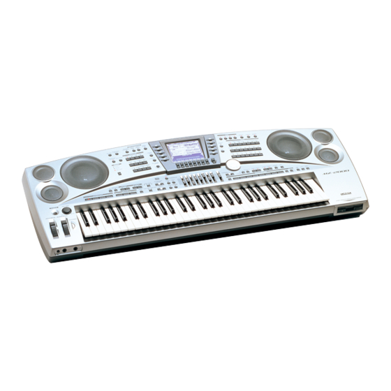
ELECTRONIC KEYBOARD
MZ-2000
MAY. 2000
COMBINATION
ACCOMP/DISK
START/STOP
VOLUME
EFFECT
SYNTH
2
1
2
DOWN
UP
BREAK
SYNC START/SYNC STOP
TEMPO
MIXER
DRAWBER
NEXT
DOWN
UP
TRANSPOSE
ARPEGGIATOR
LOWER1
LOWER2
UPPER 1
UPPER 2
SUSTAIN
MIDI
DOWN
UP
AUTO
HARMONIZE
BANK
1
2
3
4
5
6
7
8
STORE
SELECT
DISK
HELP
DEMO
MZ-2000
Advertisement
Table of Contents

Related Manuals for Casio MZ-2000


Summary of Contents for Casio MZ-2000
- Page 1 MZ-2000 MAY. 2000 COMBINATION ACCOMP/DISK rit. FADE IN/OUT START/STOP VOLUME EFFECT SYNTH TRANSPOSE ARPEGGIATOR LOWER1 LOWER2 UPPER 1 UPPER 2 SUSTAIN MIDI DOWN DOWN AUTO HARMONIZE SELECT DISK HELP DEMO BREAK SYNC START/SYNC STOP TEMPO MIXER DRAWBER BANK STORE BACK...
-
Page 2: Table Of Contents
Tempo: Variable (226 levels: =30 to 255) Chords: 3 types (CASIO CHORD, FINGERED, FULL RANGE CHORD) Rhythm Controller: Start/Stop; Intro 1, 2; Fill in BACK, NORMAL, NEXT; Break; Variations 1 to 4; Sync Start/Stop; Ritardando; Fade In/Out; Ending 1, 2... - Page 3 Punch-in Functions: Manual punch-in; auto punch-in Editing Functions: Song editing; track editing; event editing Pattern Sequencer User Pattern Areas: Memory Capacity: Approximately 22,000 notes Elements: Intro 1, 2; Fill In BACK, NORMAL, NEXT; Variations 1 through 4; Endings 1, 2 Number of Parts: 8 (drum, percussion, bass, chord 1 to 5) Recording Methods:...
- Page 4 Floppy Disk Drive Type: 3.5-inch floppy disk drive Disk Format: 2DD: 720KB MS-DOS format 2HD: 1.44MB MS-DOS format Functions: Save and load of user tones, user rhythms, Song Sequencer data, Song Studio data, Registration Memory data; playback and melody part cut of Standard MIDI files (SMF);...
-
Page 5: Block Diagram
BLOCK DIAGRAM M I D I EXP. PEDAL SUS. PEDAL HOST THRU After Sensor HOST Selecter AC Adaptor SSSF144-S06N1 AD-16ML-MJ1 SW302 Sensor Circuit AD7306 VDD(5.2V) Power IC311 DVD(5V) Bender Wheel Supply CVD(5V) Circuit FVD(5V) VDA(5V) Modulation Wheel AVCC(13.4V) VEE(25V) Power Switch MA2M PCB UPD703025AGC33 Console LED... -
Page 6: Circuit Description
CIRCUIT DESCRIPTION KEY MATRIX C2(1) C#2(1) D2(1) D#2(1) E2(1) F2(1) F#2(1) G2(1) C2(2) C#2(2) D2(2) D#2(2) E2(2) F2(2) F#2(2) G2(2) G#2(1) A2(1) A#2(1) B2(1) C3(1) C#3(1) D3(1) D#3(1) G#2(2) A2(2) A#2(2) B2(2) C3(2) C#3(2) D3(2) D#3(2) E3(1) F3(1) F#3(1) G3(1) G#3(1) A3(1) A#3(1) - Page 7 KS10 REVERB CHORUS MASTER DSP 1 DSP 2 DSP 3 DSP 4 KS11 MIDI HELP DEMO DISK KS12 ARPEGGITOP LOWER 1 UPPER 1 AUTO HARMO. LOWER 2 UPPER 2 SUSTAIN KS13 PIANO ELEC PIANO CHROMATIC P. ORGAN ACCORDION GUITAR BASS KS14 STRINGS/ORCH ENSEMBLE SOLO BRASS BRASS CLARINET...
- Page 8 (LB*) * LED is written in the matrix system, and there are three lines of serial data and 24bits in each line from CASIO CHORD (0,0) to REG MEMO 8 (B, 7). Note: Each key has two contacts, the first conatct (1) and second contact (2).
-
Page 9: Power Supply Circuit
POWER SUPPLY CIRCUIT The power supply circuit generates seven voltages as shown in the following table. VDD voltage is always generated. The others are controlled by APO signal from the CPU. Name Voltage (Manily) For operation of CPU, Reset IC, DSP, Sound source ROM, Working storage RAM, Effect RAM, +5.2V LED driver CPU, Sustain jack, MIDI jack... -
Page 10: After Sensor Adjustment
AFTER SENSOR ADJUSTMENT 1. AFTER TOUCH SENSOR ADJUSTMENT After touch sensor (code number: 1001 2063) is composed of felt, upper and lower electrode sheets, and both sided adhesive tape. Silicon spacer maintains a certain gap between the upper and the lower electrodes. Silver and carbon are printed on upper and lower electrodes. - Page 11 4. After touch sensor adjustment Make sure to perform the following adjustments after replacing after touch sensor. 4-1. Necessary equipment • Voltage regulator • Oscilloscope • Push-pull gauge (measurable up to 2,000 grams) • Screw driver FIG.2 PUSH · PULL GAUGE 4-2.
- Page 12 4-3. Adjustment method 4-3-1. Preparations 1) Turn adjustment VR’s VR951 (OFFSET) and VR952 (GAIN) on PCB SN1M counterclockwise (Fig. 4). 2) Connect voltage regulator to pin numbers 1 (GND) and 3 (AVCC source) on PCB SN1M’s CH joiner and provide 13.6 V (+/-5%) voltage. 3) Connect oscilloscope on pin numbers 1 (GND) and 2 (output voltage).
- Page 13 4-3-3. Center value (Offset value) adjustment Adjustment for the center (offset) value of the variable range of after touch sensor (refer to Fig. 7). Calculations: Present offset value (VB) is; (VA + VC) / 2 Correct offset value (V3) is; (V1 + V2) / 2 = 2.5 V Adjust the difference using VR951 (VA’) VA’...
-
Page 14: Diagnostic Program
STOP)→ MIXER→ DRAWBAR→ SYNTH→ EFFECT→ START/STOP(GR3→ GR2→ GR1→ R) → ENDING(2→ 1)→ INTRO(2→ 1)→ FADE IN/OUT→ rit.→ COMBINATION→ USER RHYTHM→ VARIOUS/WORLD→ AMERICAN→ LATIN2→ CASIO CHORD→ FINGERED→ FULL RANG CHORD→ DANCE→ JAZZ→ EUROPEAN→ LATIN1→ ROCK→ POPS→ 16BEAT→ 8BEAT→ INTERACCTIVE ACCOMP→ PATTERN SEQUNCER→ MULTITRACK→ EASY RECORD→... - Page 15 2. Press buttons in the following order. When the pressed button functions properly, a pip sounds and display indicates as follows. Button Display Button Display Button Display ASSIGNABLE ][E2][00][00] AFTER TOUCH/CONTROL [SW ][19][01][00] ELEC PIANO ][5E][01][00] VARIATION 1 ][03][01][00] PATTERN SEQUNCER [SW ][1E][01][00] PIANO ][5F][01][00]...
- Page 16 Keyboard check 1. Depress keys in the following order. 1) White key C2,D2,E2,....A6,B6,C7 2) Black key A 6,....F When all keys is proper, display indicates "Keyboard C 3 40 [OK]". Bender and Modulation check 1. Rotate the Bender wheel and Modulation wheel in the following order. Bender wheel : Max→Center→Min.→Center When the Bender wheel is proper, display indicates "Bender 00 - 7F [OK]".
- Page 17 Sustain pedal check 1. Connect the Sustain pedal(SP-2 or SP-10, option). 2. Depress and release the pedal. 3. When the sustain circuit is normal, display indecates "Foot Pedal 00 - 7F[OK]. MIDI IN/OUT test 1. Connect MIDI IN and MIDI OUT terminals with a MIDI cable. 2.
-
Page 18: Printed Circuit Boards
PRINTED CIRCUIT BOARDS Main PCB JCM765-MA1M Top view Bottom view — 17 —... - Page 19 Sub PCB JCM765-MA2M — 18 —...
-
Page 20: Schematic Diagrams
SCHEMATIC DIAGRAMS Main PCB JCM765-MA1M (1) — 19 —... - Page 21 Main PCB JCM765-MA1M (2) — 20 —...
- Page 22 Sub PCB JCM765-MA2M — 21 —...
- Page 23 Console PCB JCM765-CN1M — 22 —...
- Page 24 Console PCB JCM765-CN2M — 23 —...
- Page 25 Console PCBs JCM765-CN3M/CN4M/CN7M/CN8M/CN10M/CN11M — 24 —...
- Page 26 Console PCB JCM765-CN5M — 25 —...
- Page 27 Console PCBs JCM765-CN6M/CN9M — 26 —...
- Page 28 Keyboard PCBs JCM619T-KY1M/KY2M — 27 —...
- Page 29 Sensor PCB JCMAFT - SN1 ~ 2M — 28 —...
-
Page 30: Exploded View
EXPLODED VIEW... -
Page 31: Parts List
PARTS LIST MZ-2000 Notes: This parts list does not include the cosmetic parts, which parts are marked with item No. "R-X" in the exploded view. Contact our spare parts department if you need these parts for refurbish. Prices and specifications are subject to change with- out prior notice. - Page 32 PARTS PRICE LIST MZ-2000 Item Code No. Part Name Specification Price Code R Remarks Main PCB 10021540 PCB ASSY/MA1M TK-M241191*1(M765) 23902576 DIODE/SCHOTTKY RB501V-40TE-17 23603057 DIODE/ZENER UDZTE-173.3B 23901820 DIODE 1SS355TE-17 23602856 DIODE/ZENER UDZTE-175.6B 21141218 IC/MONOLITHIC NJM2068MD(T1) IC10 21056427 IC/L-MOS TC7WH04FU(TE12L) IC11...
- Page 33 Item Code No. Part Name Specification Price Code R Remarks IC309 21141421 IC/PHOTO COUPLER PC900V IC310 21051260 IC/C-MOS TC74HCU04AP IC311 10008345 IC/MONOLITHIC AD7306JN J301 10021361 JACK/DC HEC0740-010618 J302,303,306 36120789 JACK YKB21-5010 J307 J304-305 36120584 JACK YKB21-5012 J308 35014802 JACK/DIN YKF51-5052 J309 35022005 JACK MD-S8130-90...
- Page 34 C FOR USA/CANADA 10012068 AC CORD SET EC2K-M001A C FOR EU/GmbH/DI 10021352 AC CORD SET BC2K-M001A C FOR UK 10018311 FLOPPY DISK MZ-2000-FD-JA FOR JAPAN 10018313 FLOPPY DISK MZ-2000-FD-ES C FOR OTHERS 10018314 FLOPPY DISK MZ-2000-FD-G C FOR GmbH 10018319 FLOPPY DISK...
- Page 35 CASIO TECHNO CO.,LTD. Overseas Service Division Nishi-Shinjuku Kimuraya Bldg. 1F 5-25, Nishi-Shinjuku 7-Chome Shinjuku-ku, Tokyo 160-0023, Japan...