Advertisement
Advertisement
Table of Contents

Related Manuals for Casio ML-1


Summary of Contents for Casio ML-1
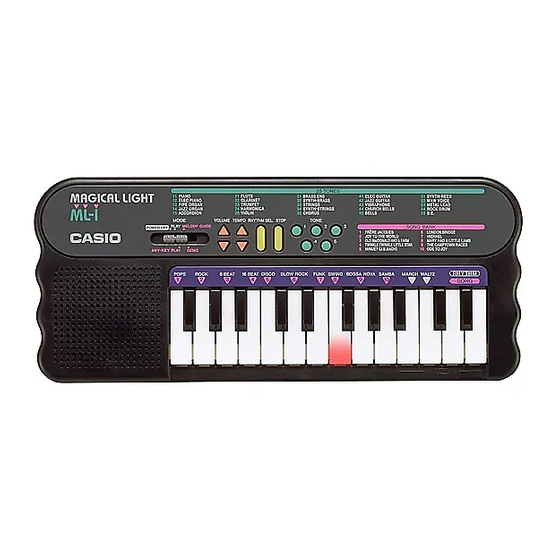
- Page 1 (with price) ML-1 ML-1 ELECTRONIC KEYBOARD...
-
Page 2: Table Of Contents
CONTENTS Specifications ......... . 1 Block Diagram . -
Page 3: Specifications
SPECIFICATIONS General Number of Keys: Illuminated keys: White keys Polyphonic: 2-note Preset Tones: Auto-Rhythms: Demonstration Tunes: Lesson Functions: 3 modes; Demo, Any-Key Play, Melody Guide Built-In Speaker: 6.5 cm dia. 0.5 W Input Rating: 1 pce. Terminal: AC Adapter Jack (DC 7.5 V) Power Source: DC: 5 AA size dry batteries Battery life: Approx. -
Page 4: Block Diagram
BLOCK DIAGRAM Illuminated Keyboard LX0~LX3 LY2~LY7 LEDs KO0~KO2 KO4~KO7 Amplifier MSM6521-10 AN8053N LSI1 Speaker KI0~KI7 VDD 5.6V AVDD 5.6V Power Supply Circuit Oscillator T1, D4 Switches Nomenclature of Keys F#3 G#3 A#3 C#4 D#4 F#4 G#4 A#4 C#5 D#5 G3 A3 B3 C4 D4 E4 B4 C5 D5... -
Page 5: Circuit Description
CIRCUIT DESCRIPTION Key Matrix Volume Volume Down Rhythm Tempo Tone 1 Stop Down Rhythm Tempo Tone 2 Tone 3 Tone 4 Tone 5 Select Melody Any Key Demo Play Guide Play Keyboard LED Matrix — 3 —... - Page 6 CPU (LSI1: MSM6521-10) Containing a sound data ROM and a DAC (Digital to Analog Converter), the CPU provides sound waveform in accordance with the pressed key and selected tone. The CPU also drives LEDs in the illuminated keyboard directly. The following table shows the pin functions of LSI1. Pin No.
-
Page 7: Troubleshooting
TROUBLESHOOTING IC LEAD IDENTIFICATION LSI1: MSM6521-10 Nature of Trouble Faulty Block Checkpoint No power Power Supply Circuit Base of T1 should receive +6 V. Emitter of T1 should provide +5.6 V. Power switch Switch contact. Power Jack (J1) Jack contact. AGND No sound at all Power Amp. -
Page 8: Pcb View And Major Waveforms
PCB VIEW AND MAJOR WAVEFORMS Key A3 OFF (5.6V) Key A3 ON 1 Key scan signal KO7 2 Sound signal output 4 LED drive signal LY6 MSM6521-10 pin 46 MSM6521-10 pin 29 Key: A3 JA connector pin 5 3 Power amp output Tone: Flute (No.21) 5 LED drive signal LX3 AN8053N pin 1... -
Page 9: Schematic Diagram
SCHEMATIC DIAGRAM JCM604-MA1M/MA2M/MA3M — 7 —... -
Page 10: Exploded View
EXPLODED VIEW — 8 —... -
Page 11: Parts List
PARTS LIST ML-1 Notes: Prices and specifications are subject to change with- out prior notice. As for spare parts order and supply, refer to the "GUIDEBOOK for Spare parts Supply", published seperately. The numbers in item column correspond to the same... - Page 12 FOB Japan Item Code No. Parts Name Specification N.R.Yen Unit Price Electrical Parts LSI1 2011 7504 LSI MSM6521-10 2114 3269 IC AN8053N 2253 0448 Transistor 2SD1858Q,R-TV6-T 2220 1387 Transistor 2SC1740SQ-TP-T 1 10 2390 0371 Diode DSK10B-BT-T 1 10 2390 1323 Diode RB100A-T32-T 1 10 D3, 6...
- Page 13 FOB Japan Item Code No. Parts Name Specification N.R.Yen Unit Price 6906 7273 Battery cover (Dark gray) M311200C*16 1 10 6922 6750 Rating label M312199-1 1 10 0009 5573 Screw 2.6x10 14 50 0009 5574 Screw, washer head 2.6x6 2 50 0009 2682 Screw 2.6x8 5 50...
- Page 14 MA0700941A...