Table of Contents
Advertisement
Quick Links
DIGITAL VIDEO RECORDER
SR-VDA300U
VCR TV CABLE/DBS
A.MONITOR
POWER
A/B
TV/VCR
DISPLAY
ENTER/OSD
1
2
3
. , ?
ABC
DEF
2
4
5
6
GHI
JKL
MNO
DBS
DAILY(M-F)
WEEKLY
7
8
9
PQRS
TUV
WXYZ
C. RESET
AUX
0
CANCEL
TIMER
4
START
STOP
DATE
CH
EXPRESS PROGRAMMING
1
PROG.
HS/STD/LS3
PROG.
SKIP SEARCH
SP/EP
CHECK
TIMER
PLAY
POWER
STOP
TV CH +
PULL-OPEN
TV
TV
VOL
VOL
–
+
TV CH –
JOG/
SHUTTLE
ASI-IN
REC LINK
ASI-REC
INSTRUCTIONS
STOP/EJECT
PL
A
Y
POWER
For Customer Use:
Enter below the Model No. and
Serial No. which are located on the
rear of cabinet. Retain this
information for future reference.
Model No.
Serial No.
LPT0788-001C
Advertisement
Table of Contents

Related Manuals for JVC SR-VDA300U


Summary of Contents for JVC SR-VDA300U
-
Page 1: Digital Video Recorder
DIGITAL VIDEO RECORDER SR-VDA300U VCR TV CABLE/DBS A.MONITOR POWER TV/VCR DISPLAY ENTER/OSD . , ? DAILY(M-F) WEEKLY PQRS WXYZ C. RESET CANCEL TIMER START STOP DATE EXPRESS PROGRAMMING PROG. HS/STD/LS3 PROG. SKIP SEARCH SP/EP CHECK TIMER REC LINK PLAY POWER... - Page 2 Dear Customer, Thank you for purchasing the JVC digital video recorder. Before use, please read the safety information and precautions con- tained in the following pages to ensure safe use of your new VCR. CAUTIONS CAUTION RISK OF ELECTRIC SHOCK...
-
Page 3: Safety Instructions
IMPORTANT PRODUCT SAFETY INSTRUCTIONS Electrical energy can perform many useful functions. But improper use can result in potential electrical shock or fire hazards. This product has been engineered and manufactured to assure your personal safety. In order not to defeat the built-in safeguards, observe the following basic rules for its installation, use and servicing. - Page 4 1. Accessories To avoid personal injury: • Do not place this product on an unstable cart, stand, tripod, bracket, or table. It may fall, causing serious injury to a child or adult, and serious damage to the product. • Use only with a cart, stand, tripod, bracket, or table recommended by the manufacturer or sold with the product.
- Page 5 A blank black or blue screen appears. The picture is fuzzy. (VHS playback) Use a cleaning tape designed specifically for D-VHS video heads (JVC D-VHS video head cleaner DFC-2) to clean the video heads. Follow the instructions that are provided with the cleaning tape.
-
Page 6: Table Of Contents
INSTALLING YOUR NEW VCR Connections ... 7 INITIAL SETTINGS Plug & Play Setting ... 9 Auto Clock Set/Auto Tuner Set ... 9 Clock Setting ... 10 Preparations ... 10 Setting clock semiautomatically — Semiauto Clock Set ... 11 Setting clock manually — Manual Clock Set ... 12 Tuner Setting ... -
Page 7: Installing Your New Vcr
INSTALLING YOUR NEW VCR Connections Antenna or Cable Coaxial Cable Flat Feeder Matching Transformer (not supplied) AC Outlet AC Power Cord IN(L-1) AUDIO VIDEO AUDIO VIDEO (MONO) IN (L-2) S VIDEO AC120V TV OUT AUDIO OUT VIDEO OUT Audio Cable (supplied) Video Cable (not supplied) -
Page 8: Component Video Connection
S-VIDEO Connection CONNECT VCR TO TV a– Connect both the RF cable and the AV cables to the TV as explained in step 3 of "Basic Connection" ( b– Connect the S-Video cable between the S VIDEO OUT terminal on the rear of the VCR and the S-VIDEO input connector on the TV. -
Page 9: Initial Settings
INITIAL SETTINGS Plug & Play Setting Auto Clock Set/Auto Tuner Set ATTENTION If you use a cable box, Plug & Play will not function; set the clock and tuner channels separately. ( It takes several minutes for the VCR to complete the Plug &... -
Page 10: Clock Setting
Clock Setting Turn on the VCR and the TV, and select the AV mode on the TV. VCR TV CABLE/DBS 2 – 7 Perform clock setting only if the clock has not been set correctly by the Plug & Play setting or if you use a cable box. -
Page 11: Setting Clock Semiautomatically
Setting clock semiautomatically — Semiauto Clock Set You can change the host channel/D.S.T. /time zone setting manually. First follow steps 1 to 3 on page 10, then go to the following steps. Set Auto Clock to ON Press %fi to move the highlight bar to “AUTO CLOCK”, then press @ # so that “ON”... -
Page 12: Setting Clock Manually - Manual Clock Set
VCR TV CABLE/DBS Setting clock manually — Manual Clock Set First follow steps 1 to 3 on page 10, then go to the following steps. 4 – 7 To make corrections any time during the process Press %fi repeatedly until the item you want to change blinks, then press @ #. -
Page 13: Tuner Setting
Tuner Setting Turn on the VCR and the TV, and select the AV mode on the TV. VCR TV CABLE/DBS Setting channels automatically — Auto Channel Set Use Auto Channel Set only if channels have not been set correctly by the Plug & Play setting. If you want to add or delete channels, and want to use the ghost reduction function, use Manual Channel Set ( INFORMATION... -
Page 14: Setting Channels Manually
VCR TV CABLE/DBS Setting channels manually — Manual Channel Set You can add the channels you want or delete the channels you do not want manually. You can also select the ghost reduction mode for each channel while adding the channels you want. Access Main Menu screen Press MENU. -
Page 15: Cable Box Control Setting
Cable Box Control Setting Suggested location Place the cable box on top of the VCR. Attach the VCR’s Controller to the top of the VCR with the Controller’s transmitter pointed towards the cable box’s remote sensor. ATTENTION: The Controller can also control a DBS receiver. If both a cable box and a DBS receiver are used, position the Controller so its signal reaches the remote sensors on both the cable box and DBS receiver. -
Page 16: Setting Cable Box Output Channel & Brand
Turn on the VCR and the TV, and select the AV mode on the TV. VCR TV CABLE/DBS Setting cable box output channel & brand After installation, set the cable box output’s channel and its brand correctly; otherwise, the Controller cannot work correctly. - Page 17 If the VCR’s memory backup expires because of a power failure, set the cable box output channel and brand again. For customers in U.S.A.: If you are unable to set the Controller, contact JVC toll free at 1-800-252-5722. CODE 1, 5, 17...
-
Page 18: Dbs Receiver Control Setting
DBS Receiver Control Setting Suggested location Place the DBS (Direct Broadcast Satellite) receiver on top of the VCR. Attach the VCR’s Controller to the top of the VCR with the Controller’s transmitter pointed towards the DBS receiver’s remote sensor. ATTENTION: The Controller can also control a cable box. -
Page 19: Setting Dbs Receiver Output Channel & Brand
Turn on the VCR and the TV, and select the AV mode on the TV. VCR TV CABLE/DBS Setting DBS receiver input channel & brand After installation, set the DBS receiver’s input channel and its brand correctly; otherwise, the Controller cannot work correctly. - Page 20 For customers in U.S.A.: If you are unable to set the Controller, contact JVC toll free at 1-800-252-5722. INITIAL SETTINGS (cont.) Access DBS Receiver Brand Set screen Press OK.
-
Page 21: Basic Playback And Recording
BASIC PLAYBACK AND RECORDING Basic Playback Turn on the VCR and the TV, and select the AV mode on the TV. POWER TIMER REC LINC POWER DIGITAL 3-D NR 3DNR S-VIDEO VIDEO (MONO) L AUDIO PULL-OPEN S-VHS ET S-ET IN F-1 MENU ASI-IN ASI-REC... -
Page 22: Basic Playback Features
Basic Playback Features Turn on the VCR and the TV, and select the AV mode on the TV. TIMER REC LINC POWER DIGITAL 3-D NR S-VIDEO 3DNR VIDEO (MONO) L AUDIO PULL-OPEN S-VHS ET S-ET MENU IN F-1 ASI-IN ASI-REC –... -
Page 23: Playing Back Tape Repeatedly - Repeat Playback
Playing back tape repeatedly — Repeat Playback You can play back a tape repeatedly (50 times). While playing back a tape, press and hold PLAY ( 3 ) for more than 5 seconds. The play indicator ( # ) on the front display panel starts flashing slowly, and a tape will be played back 50 times. -
Page 24: Automatic Operations After Rewinding
TIMER REC LINC POWER DIGITAL 3-D NR S-VIDEO 3DNR VIDEO (MONO) L AUDIO PULL-OPEN S-VHS ET S-ET MENU IN F-1 ASI-IN ASI-REC VCR TV CABLE/DBS – a, b, c – REW ( BASIC PLAYBACK AND RECORDING (cont.) The Next Function Memory “tells” the VCR what to do after rewinding is complete. -
Page 25: Locating Beginning Of Timer Recordings
Locating beginning of timer recordings — Instant Review At the press of a button, you can turn on the VCR, rewind the tape and begin to view the most recent timer- recorded program. Press REVIEW on the Remote after ensuring that the VCR is in the timer recording standby mode. -
Page 26: Basic Recording
Basic Recording Turn on the VCR and the TV, and select the AV mode on the TV. POWER TIMER REC LINC POWER DIGITAL 3-D NR S-VIDEO 3DNR VIDEO (MONO) L AUDIO PULL-OPEN S-VHS ET S-ET MENU IN F-1 ASI-IN ASI-REC VCR TV CABLE/DBS REW ( 1 ) BASIC PLAYBACK AND RECORDING (cont.) -
Page 27: S-Vhs/Vhs Recording
To pause recording Press PAUSE ( 8 ). To resume recording, press PLAY ( 3 ). To stop recording Press STOP ( 7 ) on the Remote or STOP/EJECT ( 7 on the front panel. To rewind the tape (when it is not running) Press REW ( 1 ). -
Page 28: Basic Recording Features
Basic Recording Features Turn on the VCR and the TV, and select the AV mode on the TV. TIMER REC LINC POWER DIGITAL 3-D NR S-VIDEO 3DNR VIDEO (MONO) L AUDIO PULL-OPEN S-VHS ET S-ET IN F-1 MENU ASI-IN ASI-REC –... -
Page 29: Watching One Program While Recording Another
Watching one program while recording another Engage TV mode During recording... Change the TV’s input mode from AV to TV. Select channel for viewing Select the channel you want to watch, on the TV. Showing on-screen display When “SUPERIMPOSE” is set to “ON” ( can see the current VCR status on the TV screen. - Page 30 Other useful functions for recording You can also use the following functions for recording. Recording Resume Function If there is a power outage during recording (including Instant Timer Recording, timer recording and Satellite Auto Recording), the recording will resume automatically when the power is restored to the VCR.
-
Page 31: Special Effect Playback
SPECIAL EFFECT PLAYBACK Special Effect Playback Turn on the VCR and the TV, and select the AV mode on the TV. ATTENTION When playing back a tape recorded in PRO HD (based on D-VHS) format, the JOG dial and SHUTTLE ring do not work. -
Page 32: Viewing Still Picture - Still Picture Playback
To use the JOG dial/SHUTTLE ring on the Remote, first press JOG/SHUTTLE on the remote control so that the button lights up. Still NOTE: When playing back a tape recorded in PRO HD (based on D- VHS) format, the JOG dial and SHUTTLE ring do not work. VCR TV CABLE/DBS –... -
Page 33: Viewing Slow Motion Picture
VCR TV CABLE/DBS During normal playback or still picture playback: Turn the SHUTTLE ring slowly to the right (forward slow motion) or to the left (reverse slow motion) so that slow motion playback starts.When you release the ring, a still picture appears. -
Page 34: Timer Recording
VCR Plus+ Timer Programing Turn on the VCR and the TV, and select the AV mode on the TV. TIMER REC LINC POWER DIGITAL 3-D NR S-VIDEO 3DNR VIDEO (MONO) L AUDIO PULL-OPEN S-VHS ET S-ET IN F-1 MENU ASI-IN ASI-REC VCR TV CABLE/DBS DAILY (M-F) - Page 35 Input receiving channel number The guide channel number, which is assigned to the TV or cable station for the PlusCode number that you entered in step 3, will appear automatically on the Guide Channel Set Up screen. Press the Number keys (or @ #) to input the number of the channel on which the broadcast for the PlusCode number is received on the VCR or cable box, then press OK.
-
Page 36: Changing Vcr Plus+ Setting
Changing VCR Plus+ Setting Turn on the VCR and the TV, and select the AV mode on the TV. VCR TV CABLE/DBS IMPORTANT If you have moved to a different area or if a broadcasting ® station’s channel number has been changed, the wrong VCR CH or CABLE CH number will be displayed on the Program screen ( happens, perform the following steps to set the correct... - Page 37 Access Main Menu screen Press MENU. Access Tuner Set Up screen Press %fi to move the highlight bar (arrow) to “TUNER SET UP”, then press OK. Access Guide Channel Set screen Press %fi to move the highlight bar (arrow) to “GUIDE CHANNEL SET”, then press OK.
-
Page 38: Express Timer Programing
Express Timer Programing Turn on the VCR and the TV, and select the AV mode on the TV. TIMER REC LINC POWER DIGITAL 3-D NR S-VIDEO 3DNR VIDEO (MONO) L AUDIO PULL-OPEN S-VHS ET S-ET MENU IN F-1 ASI-IN ASI-REC VCR TV CABLE/DBS DAILY (M-F) 3 –... - Page 39 Set tape speed Press HS/STD/LS3/SP/LP ( speed. Return to normal screen Press PROG. or OK. “PROGRAM COMPLETED” appears on the screen for about 5 seconds, then normal screen appears. Engage timer recording standby mode Press TIMER. The VCR turns off automatically and “‰” is displayed on the front display panel.
-
Page 40: Checking Program Settings
Turn on the VCR and the TV, and select the AV mode on the TV. VCR TV CABLE/DBS – – – Checking program settings Disengage timer Press TIMER, then press POWER. When “AUTO TIMER” ( you do not have to press TIMER. Access Program List screen Press PROG. - Page 41 ATTENTION If there is a conflict in the timer schedule and one program overlaps with another, only the parts shown below in gray will be recorded. Pattern 1: The program with the lower program number will be recorded. 10:00 11:00 Program 1 CH10 Program 2...
-
Page 42: Pro Hd System
TIMER REC LINK POWER PULL-OPEN ASI-IN ASI-REC SR-VDA300U SR-VD400U This digital video recorder is a professional deck designed for the PRO HD system. STOP/EJECT This system can record the MPEG2-TS signal on the D-VHS tape via the interface of DVB-ASI. -
Page 43: Connection And Preparation
Connection Preparation Antenna or Cable Coaxial Cable Flat Feeder Matching Transformer AC Outlet (not supplied) AC Power Cord AUDIO VIDEO S VIDEO AC120V AC IN AUDIO Outlet Video Cable Audio Cable AC Power (not supplied) (supplied) Cord (supplied) To Audio Input Connectors To Video... -
Page 44: Preparations
TIMER REC LINC POWER DIGITAL 3-D NR S-VIDEO 3DNR VIDEO (MONO) L AUDIO PULL-OPEN S-VHS ET S-ET IN F-1 MENU ASI-IN ASI-REC ASI-REC indicator ASI-IN indicator VCR TV CABLE/DBS Preparations STOP/EJECT PLAY STD/LS3 PAUSE SP/EP PRO HD POWER NOTE: ASI signals will not be recorded if above procedures are not followed. -
Page 45: Recording
Recording Turn on the VCR and the TV, and select the AV mode on the TV. POWER TIMER REC LINC POWER DIGITAL 3-D NR 3DNR S-VIDEO VIDEO (MONO) L AUDIO PULL-OPEN S-VHS ET S-ET IN F-1 MENU ASI-IN ASI-REC ASI-REC indicator VCR TV CABLE/DBS REW ( 1 ) -
Page 46: Password Set Up
Password SET UP Turn on the VCR and the TV, and select the AV mode on the TV. VCR TV CABLE/DBS CANCEL NOTES: The item with displaying the “P” is only for serviceman uses. Set and store only 1 password for every tape as a tape does not support a multiple number of passwords. -
Page 47: Playback
Playback Turn on the VCR and the TV, and select the AV mode on the TV. POWER TIMER REC LINC POWER DIGITAL 3-D NR 3DNR S-VIDEO VIDEO (MONO) L AUDIO PULL-OPEN S-VHS ET S-ET IN F-1 MENU ASI-IN ASI-REC VCR TV CABLE/DBS REW ( 1 ) NOTE: When playing back a tape recorded in PRO HD format, the... -
Page 48: Other Useful Functions
Useful Function Settings Turn on the VCR and the TV, and select the AV mode on the TV. 2 – 4 You can use the other useful function settings on the Function Set Up screens by following the procedure described below. For the functions you can set on the Function Set Up screen, see pages 49 to 53. - Page 49 Video settings [VIDEO (VHS)] V, CALIBRATION (S-VHS/VHS only) PICTURE CONTROL (S-VHS/VHS only) AUTO (NORM) EDIT SOFT SHARP DIGITAL R3 (S-VHS/VHS only) VIDEO STABILIZER (S-VHS/VHS only) * The default setting is bold in the table below. When this function is set to “ON”, this VCR checks the condition of the tape in use during playback and recording, and compensates to provide the highest-possible pictures.
- Page 50 Audio settings [AUDIO] OPTICAL OUT Dolby D 2CH-PCM 2ND AUDIO REC OTHER USEFUL FUNCTIONS (cont.) * The default setting is bold in the table below. This VCR can send the Dolby Digital bitstream or PCM Audio to external devices. When you play back a tape including the Dolby Digital bitstream, and if you have a device equipped with Dolby Digital decoder, set this function to “Dolby D”.
- Page 51 Input/Output settings [IN/OUT] TV OUTPUT 1 720to1080 NO CONV. ALLto480i TV OUTPUT 2 WIDE16:9 NORM4:3 FRONT AUX F-1 VIDEO S-VIDEO REAR AUX L-1 VIDEO S-VIDEO REAR AUX L-2 VIDEO S-VIDEO Select the apppropriate mode when playing back a D-VHS tape containing a recording of an HD (High Definition) signal: 720to1080: 720p is up-converted to 1080i and output to the TV.
- Page 52 Additional settings [ADDTL] AUTO SP = EP TIMER When this function is set to “ON”, the VCR automatically switches to EP mode to (S-VHS/VHS only) allow complete recording if there is not enough tape to record the entire program while timer-recording in SP mode. For Example .
- Page 53 When this function is set to “OFF”, you can use this terminal as the REMOTE PAUSE terminal. ( NOTE: Connection varies depending on the type of JVC TV you have. Refer to the TV’s instruction manual when making this connection. AV COMPU LINK...
-
Page 54: Satellite Auto Recording
Satellite Auto Recording This function allows you to automatically record a satellite program which is timer-programed on your DBS receiver. Preparation: Connect a DBS receiver to the AUDIO/ VIDEO IN or S VIDEO IN (L-1) connectors* on the rear; otherwise, you cannot use this function. •... -
Page 55: Jlip Id Number Setting
2 – 4 NOTE: For further details on the JLIP system or devices, consult your nearest JVC dealer. U.S. customers can contact JVC directly toll free at 1-800-252- 5722. Access Main Menu screen Press MENU. Access Initial Set Up screen Press %fi... -
Page 56: Editing
PRO HD POWER To rear panel connector Mini-plug cable (not supplied) (JVC camcorder only) Various connection for editing tapes To EDIT The following three methods can be used for editing tapes. 4 – 6 VHS to S-VHS editing (VIDEO-VIDEO connection):... - Page 57 (for S-VHS/VHS connection) Access the “VIDEO FUNCTION” screen pg. 48). If your camcorder is a JVC Master Edit Control- equipped type — go to step 6. If your camcorder is NOT a JVC Master Edit Control-equipped type — go to step 7.
-
Page 58: Edit To Or From Another Vcr/Other Devices
Edit To Or From Another VCR/Other Devices You can use your VCR as the playback or recording VCR. Refer also to the other VCR’s instruction manual for connection and its operations. Connection Ex. When using this VCR as the playback VCR This VCR (for playback) IN(L-1) AUDIO... - Page 59 VCR TV CABLE/DBS NOTE: Be sure to select “AUTO” for “PICTURE CONTROL” (or “NORM” when “V, CALIBRATION” is set to “OFF”) after you finish dubbing the tapes ( Load cassettes Insert the playback cassette into the playback VCR and the cassette to be recorded on into the recording VCR.
-
Page 60: Multi-Brand Remote Control
Once you have set the Remote to operate the TV, you do not have to set it until you replace the batteries from the Remote. JVC and PANASONIC have two codes. If the TV does not function with one code, try entering the other. -
Page 61: Cable Box Brand Setting
Cable Box Brand Setting VCR TV CABLE/DBS –3 CABLE BOX BRAND NAME BRAND CODE ARCHER 01, 05, 17 CABLETENNA 01, 17 CABLEVIEW 15, 16, 17, 21, 25 CITIZEN 15, 16, 17, 21, 25 CURTIS DIAMOND 01, 17 EASTERN GC BRAND 15, 16, 17, 21, 25 GEMINI GENERAL INSTRUMENTS... -
Page 62: Dbs Receiver Brand Setting
It's not possible to set the Remote for both your DBS receiver and a cable box at the same time. You can only set the Remote to operate one of these units at a time. (Ex.) To set the Remote to JVC 51: POWER Hold... -
Page 63: Changing Remote Control Code
VCR is initially set to respond to A code signals. You can easily modify your VCR and the Remote to respond to B code signals. When using two JVC VCRs, set two VCRs and their Remotes to different codes, so that you can operate these VCRs separately. -
Page 64: Troubleshooting
Select the AV mode on the TV. Disengage auto tracking and adjust the tracking manually ( pg. 23). The heads must be cleaned. Consult your JVC dealer. Set Audio Monitor to “HI-FI” pg. 23). CORRECTIVE ACTION Insert a cassette. Remove the cassette and cover the... - Page 65 TIMER RECORDING SYMPTOM 1. Timer recording will not work. 2. Timer programing will not work. 3. ‰ and ] on the front display panel will not stop blinking. 4. The cassette stops automatically, and ‰ and ] on the front display panel will not stop blinking.
- Page 66 ABOUT HEAD CLEANING Accumulation of dirt and other particles on the video heads may cause the playback picture to become blurred or interrupted. Be sure to contact your nearest JVC dealer if such troubles occur. ATTENTION This VCR contains microcomputers. External electronic noise or interference can cause microcomputer to malfunction. If the VCR does not operate correctly switch its power off and unplug the AC power cord from the AC supply.
-
Page 67: Error Codes And Messages
Error Codes and Messages Some error codes and messages may appear on the TV screen when operating the VCR. Refer to the chart below for the solution. CODE MESSAGE REC PROHIBITED REC PROHIBITED CAN NOT DECODE VIDEO OR AUDIO USE SET TOP BOX OR HDTV TUNER CAN NOT DECODE VIDEO OR AUDIO USE SET TOP BOX OR HDTV TUNER WAIT A MINUTE... -
Page 68: Questions And Answers
Questions and answers PLAYBACK Q. What happens if the tape reaches its end during playback or search? A. The VCR automatically rewinds it to the beginning..........Q. -
Page 69: Index
Instant Review 25 Instant Timer Recording (ITR) 28 JLIP ID Number Setting 55 Manual tracking 23 Multi-Brand Remote Controlling two JVC VCRs 63 Setting Cable Box brand 61 Setting DBS receiver brand 62 Setting TV brand 60 Next Function Memory 24... -
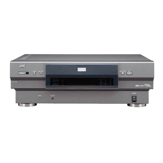
Page 70: Front Panel
Front panel TIMER REC LINC POWER S-VIDEO VIDEO (MONO) L AUDIO IN F-1 MENU ASI-IN 1 POWER button : pg. 21, 27 2 Remote sensor 3 TIMER ‰ button : pg. 35, 39, 40 4 REC LINK button : pg. 54 5 DIGITAL 3-DNR button and lamp : 6 Cassette loading slot 7 HS/STD/LS3/SP/EP button :... -
Page 71: Rear Panel
Rear panel AC120V 1 AC power cord : pg. 7 2 Cooling fan This prevents the temperature from rising inside the VCR. Do not remove it. Install the VCR so as not to block the area around the cooling fan. 3 Component video output connectors : 4 S VIDEO/AUDIO/VIDEO IN connectors (L-1): pg. -
Page 72: Front Display Panel
Front display panel - 15 1 Recording speed indicator : Timer programming indicator (“Pro” appears when PROG. or PROG. CHECK button is pressed. “Err” appears when the guide channel error occurs.) : pg. 40 2 Audio Monitor Indicators : 3 Symbolic Mode Indicators : STILL: SLOW: PLAY:... -
Page 73: On-Screen Display
On-screen display 1 Brand name of the device connected to the DVB-ASI connector 2 Model name of the device connected to the DVB-ASI connector 3 Clock time 4 Tape speed indication 5 Time counter (When “COUNT“ appears) pg. 22, 28 Tape remaining time (When “REMAIN“... -
Page 74: Remote
Remote VCR TV CABLE/DBS A.MONITOR TV/VCR DISPLAY . , ? DAILY(M-F) PQRS C. RESET CANCEL START STOP DATE EXPRESS PROGRAMMING HS/STD/LS3 PROG. PROG. SP/EP CHECK PLAY STOP TV CH + — TV CH — JOG/ SHUTTLE & How to use the Remote Before use, insert two AA size batteries into the Remote with the polarity (ª... -
Page 75: Specifications
SPECIFICATIONS GENERAL Power requirement : AC 120 V`, 60 Hz Power consumption Power on : 61 W Power off : 18 W Temperature Operating : 5°C to 40°C (41°F to 104°F) Storage : –20°C to 60°C (–4°F to140°F) Humidity Operating : 35% to 80% Operating position : Horizontal only... -
Page 76: For Servicing (Only In U.s.a.)
Sophisticated electronic products may require occasional service. Just as quality is a keyword in the engineering and production of the wide array of JVC products, service is the key to maintaining the high level performance for which JVC is world famous. The JVC service and engineering organization stands behind our products. -
Page 77: Warranty (Only In U.s.a.)
WHAT WE WILL DO: If this product is found to be defective, JVC will repair or replace defective parts at no charge to the original owner. Such repair and replacement services shall be rendered by JVC during normal business hours at JVC authorized service centers. Parts used for replacement are warranted only for the remainder of the Warranty Period. - Page 78 MEMO...
- Page 80 JVC EXPRESSLY DISCLAIMS ALL WARRANTIES, EXPRESS OR IMPLIED, AND SHALL NOT BE LIABLE FOR ANY AND ALL DAMAGES, CLAIMS OR LIABILITIES, DIRECT OR INDIRECT, ARISING FROM OR RELATING TO THE USE OF THIS PRODUCT WITH ANY OTHER PRODUCT, DEVICE, COMPONENT, PART OR MATERIAL THAT IS NON- CONFORMING OR NON-COMPATIBLE WITH THIS PRODUCT.