Advertisement
Quick Links
Advertisement

Related Manuals for Mackie SR1530


Summary of Contents for Mackie SR1530
- Page 1 Go To Bulletins SR1530 Active Speaker SERVICE MANUAL 2000 MACKIE DESIGNS, INC.
- Page 2 SERVICE ON THIS EQUIPMENT IS TO BE PERFORMED BY EXPERIENCED REPAIR TECHNICIANS ONLY...
-
Page 3: Table Of Contents
Mackie Designs, Service Technical Assistance, is available 8AM - 5PM PST, Monday through Friday for Authorized Mackie Service Centers, at 1-800-258-6883. Feel free to call with any questions and speak with a carefully-calibrated technician. If one is not available, leave a detailed message and a qualified Mackoid will return your call asap. -
Page 4: Overview
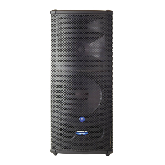
3000Hz are reproduced by a 1-inch exit compression driver. The low frequencies are produced through a high output 15-inch woofer. The SR1530 accepts a line-level signal via a female XLR input jack. A male XLR Thru jack is provided for daisy-chaining the signal to additional SR1530 cabinets. -
Page 5: Specifications
Power Handling 25 watts rms without notice. Diaphragm Material Mylar “Mackie” and the “Running Man” figure are trademarks or registered trademarks of Mackie Designs Inc. All other brand names mentioned are trademarks or registered trademarks of their respective holders, and are hereby acknowledged. -
Page 6: Test Procedure
2.2 Connect the 8 ohm load to the Mid outputs (Mid+ and Mid -). 2.3 Connect the audio generator’s output to the XLR input of the SR1530. 2.5 Initially connect the analyser and scope to the 16 ohm load on the Low Freq section. - Page 7 4 VERIFICATION OF THE LOW FREQUENCY SECTION. 4.1 Initially set the input signal to 30 mV at 100Hz. 4.2 Increase the input signal slowly until the limiter starts to stabilize the output to 35V (approximately 76.7W) with an input of approx 250 mV. 4.3 Lower the input signal until the limiter is not operating.
-
Page 8: Safety Test
Safety test You must perform the following leakage test before returning the unit to your customer. Take every safety precaution to protect yourself while doing this test. 1. Make a small loading RC circuit as shown in the diagram below, and connect the AC volt meter between the AC power source ground and any exposed metal on the unit under test. -
Page 9: Parts
SR1530 PARTS LIST PART# DESCRIPTION PAGE 13110050 SR1530 ASSEMBLY 23103130 AMPLIFIER SUBASSEMBLY 23103130 AMPLIFIER SUBASSEMBLY (dual volt) 23103130 AMPLIFIER SUBASSEMBLY (115V) 23103810 AMPLIFIER SUBASSEMBLY (100V) 23103710 AMPLIFIER SUBASSEMBLY (230V) 23103820 AMPLIFIER SUBASSEMBLY (240V) 3020490 AMPLIFIER PCB ASSEMBLY 23030110 FILTER PCB ASSEMBLY... - Page 10 PLASTIC SIDE HANDLE GRIP 34280 HANDLE GRIP 33920650 TOP HANDLE 34335REV B TOP HANDLE 33951530 MACKIE LABEL 34342 33951540 MACKIE ACTIVE LOGO 34343 33951980 RUNNING MAN LOGO 34844 33990990 PACKAGING BOX 34357 33991000 INTERNAL PACKAGING 34358 33991010 INTERNAL PACKAGING 34367...
- Page 11 23103130 AMPLIFIER SUBASSEMBLY (115V Dual-voltage Xformer) PART# DESCRIPTION QTY COMMENTS SE034341 SCHEMATIC 23020490 AMPLIFIER CIRCUIT BOARD ASSEMBLY SEE PAGE 12 23102690 WIRE ASSEMBLY UR 23103140 WIRE ASSEMBLY UR 33120320 HEATSINK 34322 HEATSINK 33951510 STICKER AMPLIFIER 34334 51150316 SCREW V.TC+M4 X10ZNN U7687 6233 51180571 SCREW V.TE M8 X90ZNN U5739 TRANSFORMER BOLT...
- Page 12 23103810 AMPLIFIER SUBASSEMBLY (100V Transformer) PART# DESCRIPTION QTY COMMENTS 23020490 AMPLIFIER CIRCUIT BOARD ASSEMBLY 23102690 WIRE ASSEMBLY UR 23102740 WIRE ASSEMBLY UR 23103680 WIRE ASSEMBLY GREEN/YELLOW 33120320 HEATSINK 34322 33890200 SPACER 35717 33951510 STICKER AMPLIFIER 34334 33953510 STICKER 100V 35698 51150331 SCREW V.TC+M4 X16ZNN U7687 51160335...
- Page 13 23103820 AMPLIFIER SUBASSEMBLY (240V Transformer) PART# DESCRIPTION QTY COMMENTS 23020490 AMPLIFIER CIRCUIT BOARD ASSEMBLY 23102690 WIRE ASSEMBLY UR 23102740 WIRE ASSEMBLY UR 23103680 WIRE ASSEMBLY GREEN/YELLOW 33120320 HEATSINK 34322 33890200 SPACER 35717 33951510 STICKER AMPLIFIER 34334 33953520 STICKER 240V 35697 51150331 SCREW V.TC+M4 X16ZNN U7687 51160335...
- Page 14 3020490 AMPLIFIER PCB ASSEMBLY PART# DESCRIPTION COMMENTS 33030370 PCB 34341 33120310 HEATSINK X TRANSISTOR 34329 33180100 BRACKET X TRANSISTOR 34327 TRANSISTOR BRACKETS 33912310 INSULATING STRIP 33238 INSULATING STRIPS 51150216 SCREW V.TC+M3 X8 ZNN U7687 6686 51150316 SCREW V.TC+M4 X10ZNN U7687 6233 52100103 WASHER 3,2X 6ZNC U6592 12272 52100110...
- Page 15 PART# DESCRIPTION COMMENTS 82212002 C2T12-101B450-TRANSISTOR BC560/C TRANSISTORS 82212019 C2T12-101C450-TRANSISTOR BC550 82232020 C2T32-102B101-TRANSISTOR TIP30 82232021 C2T32-102A101-TRANSISTOR TIP29 82262017 C2T62-143A101-MOSFET IRF530 FETS 82262018 C2T62-193B101-MOSFET IRF9540 82312005 C2A12-25532 -IC NE5532 INTEGRATED CIRCUIT 82322010 C2A22-1*3886 -IC LM3886 INTEGRATED CIRCUIT 82511006 C2F11-006 -DIODE LED RED 82512008 C2F12-008 -DIODE LED GREEN 82561001...
- Page 16 This is an older amplifier board. It may be useful as it shows Mackie-US part num- bers and some reference designators. PART# DESCRIPTION VALUE REFERENCE DESIGNATORS 110-001-00 RES CF .25W 5% 10 OHM 110-017-00 RES CF .25W 5% 47 OHM...
- Page 17 PART# DESCRIPTION VALUE REFERENCE DESIGNATORS 400-141-00 XLR 3P F VERT A-SERIES XLR1 400-142-00 XLR 3P M VERT A-SERIES XLR2 400-243-00 HDR 2P .098X1 SHRD 400-255-00 SKT HDR 10P .100X2 STR K2-3 400-256-00 SKT HDR 20P .100X2 STR 400-269-00 TERM QDISC RTA .250 PCMT J1-24 450-266-00 PCB, MAS1530 MAIN...
- Page 18 NOTE: This common parts list is for later models. The dual-voltage power transformer was replaced with four different transformers, one for each of the main primary voltages: 100V, 115V, 230V, 240V. PART# DESCRIPTION QUANTITY 21110110 WOOFER L15-64 SR 1530 11464001 RE-CONE KIT L15-64 SR 1530 21110120 MR 160 SR 1530...
-
Page 19: Service Bulletins
SR1530 active speaker modification Models affected: All SR1530 active speakers before serial number: EA 14008 Add this as part of your normal repair procedures. Symptom: Lack of midrange frequencies, or intermittent midrange Possible Cause: Poor connection of the midrange wires to the midrange transducer.