HP ProDesk 405 G2 Microtower Maintenance And Service Manual
Hp prodesk 405 g2 microtower maintenance and service guide
Hide thumbs
Also See for ProDesk 405 G2 Microtower:
- Brochure & specs (58 pages) ,
- Product end-of-life disassembly instructions (10 pages)
Table of Contents
Advertisement
Quick Links
Advertisement
Table of Contents

Related Manuals for HP ProDesk 405 G2 Microtower


Summary of Contents for HP ProDesk 405 G2 Microtower
- Page 1 Maintenance and Service Guide HP ProDesk 405 G2 Microtower...
- Page 2 This computer may require upgraded and/ or proprietor. separately purchased hardware and/or a DVD drive to install the Windows 7 software and The only warranties for HP products and take full advantage of Windows 7 functionality. services are set forth in the express warranty http://windows.microsoft.com/en-us/...
- Page 3 Safety warning notice WARNING! To reduce the possibility of heat-related injuries or of overheating the device, do not place the device directly on your lap or obstruct the device air vents. Use the device only on a hard, flat surface. Do not allow another hard surface, such as an adjoining optional printer, or a soft surface, such as pillows or rugs or clothing, to block airflow.
- Page 4 Safety warning notice...
-
Page 5: Table Of Contents
Table of contents 1 Product features ............................1 Standard configuration features ........................... 1 Front panel components ............................2 Rear panel components ............................3 Serial number location ............................4 2 Activating and Customizing the Software ......................5 Activating and customizing the software in Windows 7 ..................5 Activating the Windows operating system .................. - Page 6 Cleaning the monitor ......................... 19 Cleaning the mouse ........................... 19 Service considerations ............................19 Power supply fan ..........................19 Tools and software Requirements ....................19 Screws ............................... 20 Cables and connectors ........................20 Hard Drives ............................20 Lithium coin cell battery ........................20 SATA hard drives ..............................
- Page 7 System board ............................... 58 HP ProDesk 405 G2 system board callouts ..................60 6 Computer Setup (F10) Utility ........................62 Computer Setup (F10) Utilities ..........................62 Using Computer Setup (F10) Utilities ....................62 Computer Setup—File ........................64 Computer Setup—Storage ....................... 65 Computer Setup—Security .......................
- Page 8 Creating recovery media ......................... 121 Creating recovery media using HP Recovery Manager (select models only) ....121 Creating recovery discs with HP Recovery Disc Creator (select models only) .... 122 Creating recovery discs ................122 Backing up your information ..................123 System Restore ..........................
-
Page 9: Product Features
Product features Standard configuration features Features may vary depending on the model. For support assistance and to learn more about the hardware and software installed on your computer model, run the HP Support Assistant utility. Standard configuration features... -
Page 10: Front Panel Components
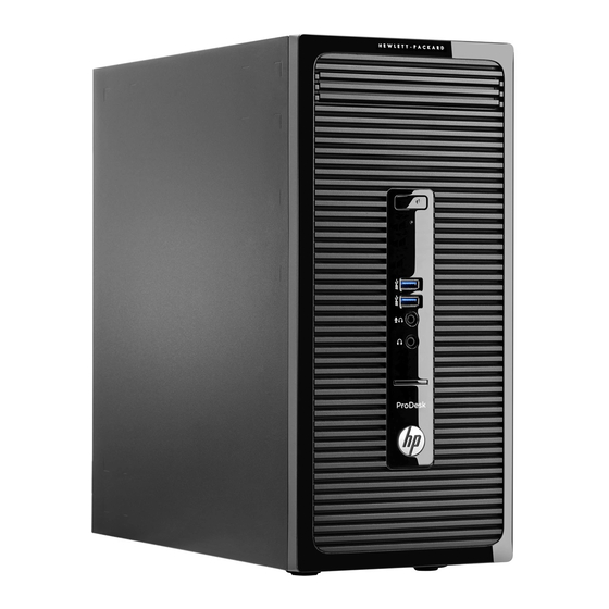
Front panel components Drive configuration may vary by model. Some models have a bezel blank covering the optical drive bay. Slim Optical Drive (optional) Hard Drive Activity Light Dual-State Power Button USB 3.0 Ports (blue) Microphone Connector Headphone Connector SD Card Reader NOTE: The Power On Light is normally white when the power is on. -
Page 11: Rear Panel Components
RJ-45 Network Connector PS/2 Keyboard Connector (purple) PS/2 Mouse Connector (green) NOTE: An optional second serial port and an optional parallel port are available from HP. The integrated graphics cannot be enabled when a discrete graphics card is installed. Rear panel components... -
Page 12: Serial Number Location
Serial number location Each computer has a unique serial number and a product ID number that are located on the exterior of the computer. Keep these numbers available for use when contacting customer service for assistance. Chapter 1 Product features... -
Page 13: Activating And Customizing The Software
5 to 10 minutes. Carefully read and follow the instructions on the screen to complete the activation. We recommend that you register your computer with HP during operating system setup so you can receive important software updates, facilitate support questions, and sign up for special offers. -
Page 14: Installing Or Upgrading Device Drivers
5 to 10 minutes. Carefully read and follow the instructions on the screen to complete the activation. We recommend that you register your computer with HP during operating system set up so you can receive important software updates, facilitate support questions, and sign up for special offers. You can also register your computer with HP using the Register with HP app on the Start screen. -
Page 15: Customizing The Monitor Display
Customizing the monitor display You can customize display settings for Windows 8 separately for the Start screen and the Desktop. To customize the Start screen: Point to the upper-right or lower-right corner of the Start screen to display the charms. Click Settings >... -
Page 16: Illustrated Parts Catalog
Illustrated parts catalog NOTE: HP continually improves and changes product parts. For complete and current information on supported parts for your computer, go to http://partsurfer.hp.com, select your country or region, and then follow the on-screen instructions. Computer major components Chapter 3 Illustrated parts catalog... - Page 17 Item Description Front bezel For use in all countries and regions except for the People’s Republic of China For use in the People’s Republic of China Access panel Power supply 300W, Active PFC + SEPA 180W, regular 180W, Energy Star 5.0 180W, Active PFC Memory modules (PC3,12800, CL11) 8-GB...
-
Page 18: Cables
Cables Item Description SATA data cable, hard drive, 10 inch, two straight ends SATA data cable, 10 inch, one straight end, one right angled end SATA data cable, 14 inch, two straight ends DisplayPort cable DMS-59 to dual VGA cable DMS-59 to dual DVI cable Adapters USB 3.0-to-USB 2.0 (200 mm) -
Page 19: Misc Parts
Front I/O assembly Fan vent cover for use in models without a chassis fan WLAN modules HP WLAN 802.11 a/b/g/n + Bluetooth 4.0 Intel Dual Band Wireless-N 7260NB 802.11 a/b/g/n 2x2 WiFi + BT4.0 Card reader Optical drive bezel blank... - Page 20 Item Description Grommet (hard drive screw, blue) WLAN antennas Clamp lock HP Ultraslim Keyed Cable Lock Thin USB powered speakers HP Webcam, 720p Drive adapters: Hard drive carrier, 2.5-inch to 3.5-inch Removable frame carrier (installs in optical drive bay; includes adapter for 2.5-inch hard drives)
-
Page 21: Drives
Drives Description Hard drives and solid-state drives (SSDs) 2 TB, 7200 rpm, 3.5 inch 1 TB, hybrid SSD, 2.5-inch 1 TB, 7200 rpm, 3.5 inch 500 GB, 10000 rpm 500 GB, 7200 rpm, 2.5 inch, self-encrypting (SED) 500 GB, hybrid SSD, 2.5 inch 500 GB, 7200 rpm, 3.5 inch 500 GB, 7200 rpm, 2.5 inch 256 GB Solid-state Drive (SSD), self-encrypting (SED) -
Page 22: Pci Boards
PCI boards Description AMD Radeon HD8350 DH PCIe x16 graphics card, 1 GB Nvidia NVS310 PCIe x16 graphics card, 512 MB Nvidia NVS315 PCIe x16 graphics card, 1 GB AMD Radeon HD8490 DP PCIe x16 graphics card, 1 GB AMD Radeon HD8470 PCIe x16 graphics card, 2 GB (for use only in the People’s Republic of China) DisplayPort connector module Nvidia GeForce GT630 DP PCIe x16 graphics card, 2 GB Printer port, PCI card... -
Page 23: Routine Care, Sata Drive Guidelines, And Disassembly Preparation
Routine care, SATA drive guidelines, and disassembly preparation This chapter provides general service information for the computer. Adherence to the procedures and precautions described in this chapter is essential for proper service. CAUTION: When the computer is plugged into an AC power source, voltage is always applied to the system board. -
Page 24: Preventing Electrostatic Damage To Equipment
Preventing electrostatic damage to equipment Many electronic components are sensitive to ESD. Circuitry design and structure determine the degree of sensitivity. The following packaging and grounding precautions are necessary to prevent damage to electric components and accessories. ● To avoid hand contact, transport products in static-safe containers such as tubes, bags, or boxes. ●... -
Page 25: Recommended Materials And Equipment
Recommended materials and equipment Materials and equipment that are recommended for use in preventing static electricity include: ● Antistatic tape ● Antistatic smocks, aprons, or sleeve protectors ● Conductive bins and other assembly or soldering aids ● Conductive foam ● Conductive tabletop workstations with ground cord of one-megohm +/- 10% resistance ●... -
Page 26: Routine Care
● Never cover the ventilation slots on the monitor with any type of material. ● Install or enable power management functions of the operating system or other software, including sleep states. Routine care General cleaning safety precautions Never use solvents or flammable solutions to clean the computer. Never immerse any parts in water or cleaning solutions;... -
Page 27: Cleaning The Monitor
● If you remove a key, use a specially designed key puller to prevent damage to the keys. This tool is available through many electronic supply outlets. CAUTION: Never remove a wide leveled key (like the space bar) from the keyboard. If these keys are improperly removed or installed, the keyboard may not function properly. -
Page 28: Screws
If an incorrect screw is used during the reassembly process, it can damage the unit. HP strongly recommends that all screws removed during disassembly be kept with the part that was removed, then returned to their proper locations. -
Page 29: Sata Hard Drives
6.0 Gb/s SATA hard drive cables SATA data cable Always use an HP approved SATA 6.0 Gb/s cable as it is fully backwards compatible with the SATA 1.5 Gb/s drives. Current HP desktop products ship with SATA 6.0 Gb/s hard drives. - Page 30 ● Some flat ribbon cables come prefolded. Never change the folds on these cables. ● Do not bend any cable sharply. A sharp bend can break the internal wires. ● Never bend a SATA data cable tighter than a 30 mm (1.18 in) radius. ●...
-
Page 31: Removal And Replacement Procedures: Microtower
NOTE: HP continually improves and changes product parts. For complete and current information on supported parts for your computer, go to http://partsurfer.hp.com, select your country or region, and then follow the on-screen instructions. Adherence to the procedures and precautions described in this chapter is essential for proper service. After completing all necessary removal and replacement procedures, run the Diagnostics utility to verify that all components operate properly. -
Page 32: Access Panel
Access panel To access internal components, you must remove the access panel: Prepare the computer for disassembly (Preparation for disassembly on page 23). Loosen the thumbscrew on the rear of the computer (1) then slide the panel back (2) and lift if off the computer (3). -
Page 33: Front Bezel
Front bezel Description Front bezel for use in all countries and regions except for the People’s Republic of China Front bezel for use in the People’s Republic of China Prepare the computer for disassembly (Preparation for disassembly on page 23). Remove the access panel (Access panel on page Lift up the three tabs on the side of the bezel (1), then rotate the bezel off the chassis (2). -
Page 34: Optical Drive Bezel Blank
Optical drive bezel blank On some models, there is a bezel blank covering the slim optical drive bay. Remove the bezel blank before installing an optical drive. To remove the bezel blank: Remove the access panel (Access panel on page Remove the front bezel (Front bezel on page To remove the bezel blank, press upward on the bottom tab and press downward on the top tab on the... -
Page 35: Memory
Memory Description 8-GB, PC3-12800 4-GB, PC3-12800 2-GB, PC3-12800 The computer comes with double data rate 3 synchronous dynamic random access memory (DDR3-SDRAM) dual inline memory modules (DIMMs). DIMMs The memory sockets on the system board can be populated with up to two industry-standard DIMMs. These memory sockets are populated with at least one preinstalled DIMM. -
Page 36: Installing Dimms
Installing DIMMs CAUTION: You must disconnect the power cord and wait approximately 30 seconds for the power to drain before adding or removing memory modules. Regardless of the power-on state, voltage is always supplied to the memory modules as long as the computer is plugged into an active AC outlet. Adding or removing memory modules while voltage is present may cause irreparable damage to the memory modules or system board. -
Page 37: Expansion Cards
Expansion cards Nvidia NVS310 PCIe x16 graphics card, 512 MB Nvidia NVS315 PCIe x16 graphics card, 1 GB AMD Radeon HD8490 DP PCIe x16 graphics card, 1 GB AMD Radeon HD8470 PCIe x16 graphics card, 2 GB (for use only in the People’s Republic of China) AMD Radeon HD8350 DH PCIe x16 graphics card, 1 GB Nvidia GeForce GT630 DP PCIe x16 graphics card, 2 GB Intel PRO/1000 single port GbE NIC, includes bracket... - Page 38 Before installing an expansion card, remove the expansion slot cover or the existing expansion card. NOTE: Before removing an installed expansion card, disconnect any cables that may be attached to the expansion card. If you are installing an expansion card in a vacant socket, you must slide one of the expansion slot covers up and out of the chassis or use a flatblade screwdriver to pry out one of the metal shields on the rear panel that covers the expansion slot.
- Page 39 If you are removing a PCI Express x16 card, pull the retention arm on the back of the expansion socket away from the card and carefully rock the card back and forth until the connectors pull free from the socket. Lift the card straight up then away from the inside of the chassis to remove it. Be sure not to scrape the card against other components.
- Page 40 Press the expansion card retention latch against the back of the chassis (1) and slide it down (2) so that the tabs on the back of the latch slide into the notches on the chassis and then replace the screw that secures the latch (3).
-
Page 41: Drives
Drives Description Optical drives DVD±RW drive DVD-ROM drive Blu-ray BD-RW SuperMulti XL Drive Hard drives and solid-state drives (SSDs) 2 TB, 7200 rpm, 3.5 inch 1 TB, hybrid SSD, 2.5-inch 1 TB, 7200 rpm, 3.5 inch 500 GB, 10000 rpm 500 GB, 7200 rpm, 2.5 inch, self-encrypting (SED) 500 GB, hybrid SSD, 2.5 inch 500 GB, 7200 rpm, 3.5 inch... - Page 42 ● HP has provided four extra 6-32 hard drive mounting screws installed on the front of the chassis behind the bezel (1). The mounting screws are required for 3.5-inch and 2.5-inch hard drives installed in the hard drive bays. If you are replacing a drive, remove the mounting screws from the old drive and install them in the new drive.
-
Page 43: Drive Positions
Drive positions Slim optical drive bay 3.5-inch internal hard drive bay 2.5-inch internal hard drive bay 3.5-inch internal hard drive bay NOTE: The drive configuration on your computer may be different than the drive configuration shown above. NOTE: The upper hard drive bay can contain either a 3.5-inch hard drive or a 2.5-inch hard drive, but not both. To verify the type and size of the storage devices installed in the computer, run Computer Setup. -
Page 44: Removing A Slim Optical Drive
Removing a slim optical drive CAUTION: All removable media should be taken out of a drive before removing the drive from the computer. Prepare the computer for disassembly (Preparation for disassembly on page Remove the access panel (Access panel on page Remove the front bezel (Front bezel on page Disconnect the power cable and data cable from the back of the optical drive. - Page 45 Align the small pins on the release latch with the small holes on the side of the drive and press the latch firmly onto the drive. Slide the optical drive through the front bezel (1) all the way into the bay so that the green latch locks onto the chassis frame (2).
-
Page 46: Removing A 3.5-Inch Hard Drive
Removing a 3.5-inch hard drive NOTE: Before you remove the old hard drive, be sure to back up the data from the old hard drive so that you can transfer the data to the new hard drive. Prepare the computer for disassembly (Preparation for disassembly on page Remove the access panel (Access panel on page... -
Page 47: Installing A 3.5-Inch Hard Drive
Slide the drive into the drive bay (1) and install the four 6-32 mounting screws (2) to secure the drive in place. NOTE: HP has supplied four extra 6-32 mounting screws on the front of the chassis behind the bezel. Refer to Drives on page 33 for an illustration of the location of the extra mounting screws. -
Page 48: Removing A 2.5-Inch Hard Drive
Removing a 2.5-inch hard drive NOTE: Before you remove the old hard drive, be sure to back up the data from the old hard drive so that you can transfer the data to the new hard drive. Prepare the computer for disassembly (Preparation for disassembly on page Remove the access panel (Access panel on page... -
Page 49: Installing A 2.5-Inch Hard Drive
Slide the drive into the drive bay (1) and install the four 6-32 mounting screws (2) to secure the drive in place. NOTE: HP has supplied four extra 6-32 mounting screws on the front of the chassis behind the bezel. Refer to Drives on page 33 for an illustration of the location of the extra mounting screws. -
Page 50: Wlan Module
WLAN module Description HP WLAN 802.11 a/b/g/n + Bluetooth 4.0 Intel Dual Band Wireless-N 7260NB 802.11 a/b/g/n 2x2 WiFi + BT4.0 You can install a WLAN module using a PCIe expansion card. The module is secured to the expansion card with two Phillips screw and has two connected antennas. - Page 51 Remove the two Phillips screws (2) that secure the module to the PCIe card. Lift the module to a 45-degree angle, and then pull it away to remove it from the socket (3). To install a WLAN module in the socket on the PCIe card, noting the notch (1) in the socket, insert the module into the socket (2).
- Page 52 Connect the antenna cables from the module (5). Chapter 5 Removal and replacement procedures: Microtower...
-
Page 53: Rtc Battery
The lithium battery is only used when the computer is NOT connected to AC power. HP encourages customers to recycle used electronic hardware, HP original print cartridges, and rechargeable batteries. For more information about recycling programs, go to http://www.hp.com/recycle. - Page 54 Type 2 To release the battery from its holder, squeeze the metal clamp that extends above one edge of the battery. When the battery pops up, lift it out (1). To insert the new battery, slide one edge of the replacement battery under the lip of the holder with the positive side up.
-
Page 55: Displayport Connector Module
Reset the date and time, your passwords, and any special system setups using Computer Setup. Lock any security devices that were disengaged when the computer access panel was removed. DisplayPort connector module Prepare the computer for disassembly (Preparation for disassembly on page 23). -
Page 56: Front I/O And Power Switch Assembly
Front I/O and power switch assembly Prepare the computer for disassembly (Preparation for disassembly on page 23). Remove the access panel (Access panel on page 24). Remove the front bezel (Front bezel on page 25). From the inside of the computer, disconnect the three front I/O cables from the following system board connectors: ●... - Page 57 Remove the cables from the metal clip built into the base pan. From the front of the computer, remove the Torx T15 screw (1) that secures the assembly to the chassis. Press the latch on the left side of the assembly (2), and then rotate the left side of the assembly into the chassis (3).
-
Page 58: Fan Sink
Fan sink Description Fan sink, standard Fan sink, BFR/PVC free WARNING! To reduce risk of personal injury from hot surfaces, allow the internal system components to cool before touching. NOTE: System board appearance may vary. Prepare the computer for disassembly (Preparation for disassembly on page 23). -
Page 59: Speaker
Speaker Prepare the computer for disassembly (Preparation for disassembly on page 23). Remove the access panel (Access panel on page 24). From the outside front of the chassis, remove the two Torx T15 screws that secure the speaker to the front of the chassis. - Page 60 Under the drive cage, remove the speaker cable from the clip built into the base of the chassis (1), and then remove the speaker from the chassis (2). To replace the speaker, reverse the removal procedures. Chapter 5 Removal and replacement procedures: Microtower...
-
Page 61: Fan
IMPORTANT: System fan only ships with select models. Most models do NOT include a system fan. On models without a fan, Mylar covers the inside of the fan grill on the rear of the computer. Prepare the computer for disassembly (Preparation for disassembly on page 23). - Page 62 Lift the fan out of the chassis (2). To install the fan, reverse the removal procedure. Be sure to orient the air flow out of the computer. Chapter 5 Removal and replacement procedures: Microtower...
-
Page 63: Power Supply
Power supply NOTE: System board appearance may vary. Description 300W, Active PFC + SEPA 180W, Energy Star 5.0 180W, Active PFC 180W, regular Prepare the computer for disassembly (Preparation for disassembly on page 23). Remove the access panel (Access panel on page 24). - Page 64 Power supply connectors connect to the drives as follows: ● P3 connector: primary hard drive ● P5 connector: primary optical drive ● P4 connector: secondary hard drive From the outside rear of the chassis, remove the four silver Torx T15 screws that secure the power supply to the chassis.
- Page 65 From the inside of the chassis, press the power supply release button (1), slide the power supply toward the front of the computer (2) , rotate slightly into the computer so the power supply clears the lip on the top of the chassis, and then lift the power supply out of the chassis (3). To install the power supply, reverse the removal procedure.
-
Page 66: System Board
System board NOTE: All system board spare part kits include replacement thermal material. NOTE: System board appearance may vary. Description System board with AMD Quad-Core A8-6410 Accelerated Processor with AMD Radeon HD 8400 Discrete-Class Graphics (2.4GHz, 2MB L2 cache, 25W) For use in models without Windows 8.1 For use in models with Windows 8.1 Standard For use in models with Windows 8.1 Professional... - Page 67 Slide the system board toward the front of the computer to disengage the I/O panel(2), and then lift the system board out of the computer (3). When reinstalling the system board, first insert the I/O panel back into the slots in the rear of the chassis, and then align the board with the chassis screw holes.
-
Page 68: Hp Prodesk 405 G2 System Board Callouts
HP ProDesk 405 G2 system board callouts Sys Bd Label Sys Bd Color Component Sys Bd Label Sys Bd Color Component Connector Connector CMOS CMOS button Yellow Reset CMOS PB/LED Front I/O Black Front I/O/power switch CPUFAN Processor fan White... - Page 69 Processor Green Processor IN/OUT Input and Silver Headphone and (soldered on) output jacks microphone jacks PWRCPU Processor White 4-pin processor USB ports Silver USB ports power power connector FRONT Front I/O Blue Front I/O/power DISPLAYPORT DisplayPort Silver DisplayPort USB3.0 switch connector Battery Black...
-
Page 70: Computer Setup (F10) Utility
Computer Setup (F10) Utility Computer Setup (F10) Utilities Use Computer Setup (F10) Utility to do the following: ● Change factory default settings. ● Set the system date and time. ● Set, view, change, or verify the system configuration, including settings for processor, graphics, memory, audio, storage, communications, and input devices. - Page 71 NOTE: If you do not press at the appropriate time, you must restart the computer and again repeatedly press when the monitor light turns green to access the utility. NOTE: If the Computer Setup (F10) Utility is set to “fast boot”, use one of the following procedures to access Computer Setup: ●...
-
Page 72: Computer Setup-File
Computer Setup—File NOTE: Support for specific Computer Setup options may vary depending on the hardware configuration. Table 6-1 Computer Setup—File Option Description System Information Lists: ● Manufacturer ● Product name ● SKU number ● Serial number ● Asset tag ● Born on date ●... -
Page 73: Computer Setup-Storage
Computer Setup—Storage NOTE: Support for specific Computer Setup options may vary depending on the hardware configuration. Table 6-2 Computer Setup—Storage Option Description Device Configuration Lists all installed BIOS-controlled storage devices. When a device is selected, detailed information and options are displayed. The following options may be presented: ●... -
Page 74: Computer Setup-Security
Table 6-2 Computer Setup—Storage (continued) Shortcut to Temporarily Override Boot Order To boot one time from a device other than the default device specified in Boot Order, restart the computer and press (to access the boot menu) and then (Boot Order), or only (skipping the boot menu) when the monitor light turns green. - Page 75 Table 6-3 Computer Setup—Security (continued) ● Front USB Ports ● Rear USB Ports ● Internal USB Ports Slot Security Allows you to disable any PCI or PCI Express slot. Default is enabled. Network Boot Enables/disables the computer’s ability to boot from an operating system installed on a network server. (Feature available on NIC models only;...
-
Page 76: Computer Setup-Power
(PK) that verifies kernels during system start up, allowing you to use alternative operating systems. Selecting HP Keys causes the computer boot using the preloaded HP-specific boot keys. Default is HP Keys. -
Page 77: Computer Setup-Advanced
Computer Setup—Advanced NOTE: Support for specific Computer Setup options may vary depending on the hardware configuration. Table 6-5 Computer Setup—Advanced (for advanced users) Option Heading Power-On Options Allows you to set: ● POST messages (enable/disable). Enabling this feature will cause the system to display POST error messages, which are error messages displayed on the monitor during the Power On Self Test if the BIOS encounters some kind of problem while starting the PC. -
Page 78: Recovering The Configuration Settings
Recovering the Configuration Settings This method of recovery requires that you first perform the Save to Removable Media command with the Computer Setup (F10) Utility before Restore is needed. (See Computer Setup—File on page 64 in the Computer Setup—File table.) NOTE: It is recommended that you save any modified computer configuration settings to a USB flash media device and save the device for possible future use. -
Page 79: Troubleshooting Without Diagnostics
Helpful hints on page 72 in this guide. To assist you in resolving problems online, HP Instant Support Professional Edition provides you with self- solve diagnostics. If you need to contact HP support, use HP Instant Support Professional Edition's online chat feature. -
Page 80: Helpful Hints
If it becomes necessary to call for technical assistance, be prepared to do the following to ensure that your service call is handled properly: ● Be in front of your computer when you call. ● Write down the computer serial number, product ID number, and monitor serial number before calling. ●... -
Page 81: Solving General Problems
● If you have installed an operating system other than the factory-installed operating system, check to be sure that it is supported on the system. ● If the system has multiple video sources (embedded, PCI, or PCI-Express adapters) installed (embedded video on some models only) and a single monitor, the monitor must be plugged into the monitor connector on the source selected as the primary VGA adapter. - Page 82 In case of forgotten password, power loss, or computer malfunction, you must manually disable the Smart Cover lock . A key to unlock the Smart Cover Lock is not available from HP. Keys are typically available from a hardware store.
- Page 83 Poor performance. Cause Solution Processor is too hot. Make sure airflow to the computer is not blocked. Leave a 10.2-cm (4-inch) clearance on all vented sides of the computer and above the monitor to permit the required airflow. Make sure fans are connected and working properly (some fans only operate when needed).
- Page 84 Computer powered off automatically and the Power LED flashes Red two times, once every second, followed by a two second pause, and the computer beeps two times. (Beeps stop after fifth iteration but LEDs continue flashing). Cause Solution Processor thermal protection activated: Ensure that the computer air vents are not blocked and the processor cooling fan is running.
-
Page 85: Solving Power Problems
Solving power problems Common causes and solutions for power problems are listed in the following table. Power supply shuts down intermittently. Cause Solution If equipped with a voltage selector, voltage selector switch on Select the proper AC voltage using the selector switch. rear of computer chassis (some models) not switched to correct line voltage (115V or 230V). -
Page 86: Solving Hard Drive Problems
Solving hard drive problems Hard drive error occurs. Cause Solution Hard disk has bad sectors or has failed. In Windows 7, click Start, click Computer, and right-click on a drive. Select Properties, and then select the Tools tab. Under Error-checking click Check Now. In Windows 8, on the Start screen type e, and then select File Explorer from the list of applications. - Page 87 Nonsystem disk/NTLDR missing message. Cause Solution The system is trying to start from the hard drive but the hard Perform Drive Protection System (DPS) testing in system ▲ drive may have been damaged. ROM. System files missing or not properly installed. Insert bootable media and restart the computer.
-
Page 88: Solving Media Card Reader Problems
Solving media card reader problems Media card will not work in a digital camera after formatting it in Windows. Cause Solution By default, Windows will format any media card with a capacity Either format the media card in the digital camera or select FAT greater than 32MB with the FAT32 format. -
Page 89: Solving Display Problems
Do not know how to remove a media card correctly. Cause Solution NOTE: Never remove the card when the green LED is flashing After installing the media card reader and booting to Windows, the reader and the inserted cards are not recognized by the computer. - Page 90 Reseat DIMMs. Power on the system. Replace DIMMs one at a time to isolate the faulty module. Replace third-party memory with HP memory. Replace the system board. Blank screen and the power LED flashes Red six times, once every second, followed by a two second pause, and the computer beeps six times.
- Page 91 Blank screen and the power LED flashes Red seven times, once every second, followed by a two second pause, and the computer beeps seven times. (Beeps stop after fifth iteration but LEDs continue flashing.) Cause Solution System board failure (ROM detected failure prior to video). Replace the system board.
- Page 92 Image is not centered. Cause Solution Position may need adjustment. Press the monitor's Menu button to access the OSD menu. Select ImageControl/ Horizontal Position or Vertical Position to adjust the horizontal or vertical position of the image. “No Connection, Check Signal Cable” displays on screen. Cause Solution Monitor video cable is disconnected.
-
Page 93: Solving Audio Problems
Web site, select the appropriate monitor, and download either SP32347 or SP32202: http://www.hp.com/support Graphics card is not seated properly or is bad (some models). Reseat the graphics card. Replace the graphics card. - Page 94 Sound does not come out of the speaker or headphones. Cause Solution Software volume control is turned down or muted. Double-click the Speaker icon on the taskbar, then make sure that Mute is not selected and use the volume slider to adjust the volume.
-
Page 95: Solving Printer Problems
Computer appears to be locked up while recording audio. Cause Solution The hard disk may be full. Before recording, make sure there is enough free space on the hard disk. You can also try recording the audio file in a compressed format. -
Page 96: Solving Keyboard And Mouse Problems
Printer will not print. Cause Solution If you are on a network, you may not have made the connection Make the proper network connections to the printer. to the printer. Printer may have failed. Run printer self-test. Printer will not turn on. Cause Solution The cables may not be connected properly. - Page 97 Keyboard commands and typing are not recognized by the computer. Cause Solution Keyboard connector is not properly connected. Shut down the computer, reconnect the keyboard to the back of the computer, and then restart the computer. Program in use has stopped responding to commands. Shut down your computer using the mouse and then restart the computer.
-
Page 98: Solving Hardware Installation Problems
Mouse does not respond to movement or is too slow. Cause Solution Mouse may need repair. See the Worldwide Limited Warranty for terms and conditions. Computer is in Sleep state. Press the power button to resume from Sleep state. CAUTION: When attempting to resume from Sleep state, do not hold down the power button for more than four seconds. - Page 99 Reseat DIMMs. Power on the system. Replace DIMMs one at a time to isolate the faulty module. Replace third-party memory with HP memory. Replace the system board. Power LED flashes Red six times, once every second, followed by a two second pause, and the computer beeps six times. (Beeps stop after fifth iteration but LEDs continue flashing.)
-
Page 100: Solving Network Problems
Power LED flashes Red six times, once every second, followed by a two second pause, and the computer beeps six times. (Beeps stop after fifth iteration but LEDs continue flashing.) Cause Solution For systems with integrated graphics, replace the system board. Power LED flashes Red ten times, once every second, followed by a two second pause, and the computer beeps ten times. - Page 101 Table 7-2 Solving Network Problems (continued) Wake-on-LAN feature is not functioning. Cause Solution Click the Configure button. Click the Power Management tab, then enable the appropriate Wake-on LAN option. Network driver does not detect network controller. Cause Solution Network controller is disabled. Run Computer Setup and enable network controller.
- Page 102 Table 7-2 Solving Network Problems (continued) Network status link light never flashes. NOTE: The network status light is supposed to flash when there is network activity. Cause Solution Network driver is not properly loaded. Reinstall network drivers. System cannot autosense the network. Disable auto-sensing capabilities and force the system into the correct operating mode.
- Page 103 Table 7-2 Solving Network Problems (continued) Network controller stopped working when an expansion board was added to the computer. Cause Solution The network controller requires drivers. Verify that the drivers were not accidentally deleted when the drivers for a new expansion board were installed. The expansion board installed is a network card (NIC) and Under the Computer Setup Advanced menu, change the resource conflicts with the embedded NIC.
-
Page 104: Solving Memory Problems
Management Engine (ME) settings). To avoid damage to the DIMMs or the system board, you must unplug the computer power cord before attempting to reseat, install, or remove a memory module. For those systems that support ECC memory, HP does not support mixing ECC and non-ECC memory. Otherwise, the computer will not boot the operating system. - Page 105 LEDs continue flashing.) Cause Solution Memory is installed incorrectly or is bad. Reseat DIMMs. Power on the system. Replace DIMMs one at a time to isolate the faulty module. Replace third-party memory with HP memory. Replace the system board. Solving memory problems...
-
Page 106: Solving Cd-Rom And Dvd Problems
Solving CD-ROM and DVD problems If you encounter CD-ROM or DVD problems, see the common causes and solutions listed in the following table or to the documentation that came with the optional device. System will not boot from CD-ROM or DVD drive. Cause Solution The device is attached to a SATA port that has been hidden in the... - Page 107 Movie will not play in the DVD drive. Cause Solution Decoder software is not installed. Install decoder software. Damaged media. Replace media. Movie rating locked out by parental lock. Use DVD software to remove parental lock. Media installed upside down. Reinstall media.
-
Page 108: Solving Usb Flash Drive Problems
Solving USB flash drive problems If you encounter USB flash drive problems, common causes and solutions are listed in the following table. USB flash drive is not seen as a drive letter in Windows. Cause Solution The drive letter after the last physical drive is not available. Change the default drive letter for the flash drive in Windows. -
Page 109: Solving Internet Access Problems
A USB device, headphone, or microphone is not recognized by the computer. Cause Solution The correct device driver is not installed. Install the correct driver for the device. You might need to reboot the computer. The cable from the device to the computer does not work. If possible, replace the cable. -
Page 110: Solving Software Problems
If you have installed an operating system other than the factory-installed operating system, check to be sure it is supported on the system. If you encounter software problems, see the applicable solutions listed in the following table. Computer will not continue and the HP logo does not display. Cause Solution ROM issue - POST error has occurred. - Page 111 Computer will not continue after HP logo screen displays. Cause Solution To access Automatic Repair: Press the Windows logo to open the Settings charm. Select Change PC Settings, select General, and then under Advanced startup, click Restart now. Select Troubleshoot, select Advanced options, and then select Automatic Repair.
-
Page 112: Post Error Messages
POST error messages This appendix lists the error codes, error messages, and the various indicator light and audible sequences that you may encounter during Power-On Self-Test (POST) or computer restart, the probable source of the problem, and steps you can take to resolve the error condition. POST Message Disabled suppresses most system messages during POST, such as memory count and non- error text messages. - Page 113 Memory configuration incorrect. Run Computer Setup or Windows utilities. Make sure the memory module(s) are installed properly. If third-party memory has been added, test using HP-only memory. Verify proper memory module type. 201-Memory Error RAM failure. Ensure memory modules are correctly installed.
- Page 114 Control panel message Description Recommended action 301-Keyboard Error Keyboard failure. Reconnect keyboard with computer turned off. Check connector for bent or missing pins. Ensure that none of the keys are depressed. Replace keyboard. 303-Keyboard Controller Error I/O board keyboard controller. Reconnect keyboard with computer turned off.
- Page 115 Control panel message Description Recommended action 601-Diskette Controller Error Diskette controller circuitry or floppy drive Check and/or replace cables. circuitry incorrect. Clear CMOS. (See Appendix B, Password security and resetting CMOS on page 112.) Replace diskette drive. Replace the system board. 605-Diskette Drive Type Error Mismatch in drive type.
- Page 116 Control panel message Description Recommended action Apply hard drive firmware patch if applicable. (Available at http://www.hp.com/support.) Back up contents and replace hard drive. 1796-SATA Cabling Error One or more SATA devices are improperly Ensure SATA connectors are used in ascending attached.
-
Page 117: Interpreting Post Diagnostic Front Panel Leds And Audible Codes
Control panel message Description Recommended action Replace keyboard. Parity Check 2 Parity RAM failure. Run Computer Setup and Diagnostic utilities. Interpreting POST diagnostic front panel LEDs and audible codes This section covers the front panel LED codes as well as the audible codes that may occur before or during POST that do not necessarily have an error code or text message associated with them. - Page 118 Reseat DIMMs. is solved. Replace DIMMs one at a time to isolate the faulty module. Replace third-party memory with HP memory. Replace the system board. Red Power LED flashes six times, Pre-video graphics error. For systems with a graphics card: once every second, followed by Reseat the graphics card.
- Page 119 Activity Beeps Possible cause Recommended action to the appropriate voltage. Proper voltage setting depends on your region. Replace the system board. Press and hold the power button for less than 4 seconds. If the hard drive LED does not turn on white then: Check that the unit is plugged into a working AC outlet.
-
Page 120: Password Security And Resetting Cmos
Password security and resetting CMOS This computer supports security password features, which can be established through the Computer Setup Utilities menu. This computer supports two security password features that are established through the Computer Setup Utilities menu: setup password and power-on password. When you establish only a setup password, any user can access all the information on the computer except Computer Setup. -
Page 121: Changing A Setup Or Power-On Password
Shut down the operating system properly, then turn off the computer and any external devices, and disconnect the power cord from the power outlet. With the power cord disconnected, press the power button again to drain the system of any residual power. -
Page 122: Deleting A Setup Or Power-On Password
When the key icon appears, type your current password, a slash (/) or alternate delimiter character, your new password, another slash (/) or alternate delimiter character, and your new password again as shown: current password/new password/new password NOTE: Type the new password carefully since the characters do not appear on the screen. Press Enter. - Page 123 Remove the access panel. CAUTION: Pushing the CMOS button will reset CMOS values to factory defaults. It is important to back up the computer CMOS settings before resetting them in case they are needed later. Back up is easily done through Computer Setup. See Computer Setup (F10) Utility on page 62 for information on backing up the CMOS settings.
-
Page 124: 10 Hp Pc Hardware Diagnostics
Why run HP PC Hardware Diagnostics The HP PC Hardware Diagnostic tools simplify the process of diagnosing hardware issues and expedite the support process when issues are found. The tools save time by pinpointing the component that needs to be replaced. - Page 125 Click Find Now to let HP automatically detect your product. Select your computer model, and then select your operating system. In the Diagnostic section, click HP UEFI Support Environment. Click Download, and then select Run. Downloading HP PC Hardware Diagnostics (UEFI) to a USB device 117...
-
Page 126: 11 System Backup And Recovery
Backing up, restoring, and recovering in Windows 8.1 or Windows 8 Your computer includes tools provided by HP and Windows to help you safeguard your information and retrieve it if you ever need to. These tools will help you return your computer to a proper working state or even back to the original factory state, all with simple steps. -
Page 127: Using Reset When The System Is Not Responding
For Windows 8, from the Start screen, type c, and then select Computer. NOTE: If the HP Recovery partition is not listed, or you cannot check for its presence, you must recover using the recovery media you created; see Recovery using the Windows recovery USB flash drive on page 119. -
Page 128: Recovery Using Windows Operating System Media (Purchased Separately)
Backing up, restoring, and recovering in Windows 7 Your computer includes tools provided by HP and Windows to help you safeguard your information and retrieve it if you ever need to. These tools will help you return your computer to a proper working state or even back to the original factory state, all with simple steps. -
Page 129: Creating Recovery Media
123. NOTE: HP recommends that you print the recovery procedures and save them for later use, in case of system instability. Creating recovery media After you successfully set up the computer, create recovery media. The media can be used to reinstall the original operating system in cases where the hard drive is corrupted or has been replaced. -
Page 130: Creating Recovery Discs With Hp Recovery Disc Creator (Select Models Only)
Creating recovery discs with HP Recovery Disc Creator (select models only) HP Recovery Disc Creator is a software program that offers an alternative way to create recovery discs on select models. After you successfully set up the computer, you can create recovery discs using HP Recovery Disc Creator. -
Page 131: Backing Up Your Information
Select Start > All Programs > Productivity and Tools > HP Recovery Disc Creator. Select Windows disk. From the drop-down menu, select the drive for burning the recovery media. Click the Create button to start the burning process. Label the disc after you create it, and store it in a secure place. -
Page 132: System Recovery
If you were not able to create system recovery DVDs or USB flash drive, you can order a recovery disc set from support. Go to http://www.hp.com/support, select your country or region, and follow the on-screen instructions. -
Page 133: System Recovery When Windows Is Not Responding
Disconnect all peripheral devices from the computer, except the monitor, keyboard, and mouse. Press the power button to turn on the computer. As soon as you see the HP logo screen, repeatedly press the key on your keyboard until the Windows is Loading Files…... -
Page 134: Using Hp Recovery Disc Operating System Discs (Select Models Only)
Using HP Recovery Disc operating system discs (select models only) Use the steps provided in this section if you used HP Recovery Disc Creator to create a Windows 7 operating system DVD and a Driver Recovery DVD. If you created recovery media using... - Page 135 After the repair is completed: Eject the Windows 7 operating system DVD and then insert the Driver Recovery DVD. Follow the on-screen instructions to install the Hardware Enabling Drivers first, and then install Recommended Applications. Backing up, restoring, and recovering in Windows 7 127...
-
Page 136: Appendix A Power Cord Set Requirements
Power cord set requirements The power supplies on some computers have external power switches. The voltage select switch feature on the computer permits it to operate from any line voltage between 100-120 or 220-240 volts AC. Power supplies on those computers that do not have external power switches are equipped with internal switches that sense the incoming voltage and automatically switch to the proper voltage. -
Page 137: Country-Specific Requirements
Country-specific requirements Additional requirements specific to a country are shown in parentheses and explained below. Country Accrediting Agency Country Accrediting Agency Australia (1) EANSW Italy (1) Austria (1) Japan (3) METI Belgium (1) CEBC Norway (1) NEMKO Canada (2) Sweden (1) SEMKO Denmark (1) DEMKO... -
Page 138: Appendix B Statement Of Volatility
Follow the instructions to flash the BIOS that are found on the website. Flashing the BIOS will reset it back to factory settings. Turn on the system, and while system is powering on, and after the HP splash screen, press the to enter BIOS setup screen. - Page 139 Locate the green two pin password jumper on header E49 (labeled PSWD) and remove it. Remove the AC power, wait 10 seconds until the unit AC power has drained out, then press the clear CMOS button. This is typically a yellow push button (labeled CMOS). Replace the hood and AC power cord and turn the computer on.
-
Page 140: Appendix C Specifications
Specifications Chassis 13.98 in 355 mm Height 6.50 in 165 mm Width 14.10 in 358 mm Depth Approximate Weight 14.33 lb 6.50 kg Temperature Range 50° to 95°F 10° to 35°C Operating -22° to 140°F -30° to 60°C Nonoperating NOTE: Operating temperature is derated 1.0°... - Page 141 Current Leakage with Energy Efficient Power Supply <600uA / 230 VAC This system utilizes an active power factor corrected power supply. This allows the system to pass the CE mark requirements for use in the countries of the European Union. The active power factor corrected power supply also has the added benefit of not requiring an input voltage range select switch.
-
Page 142: Index
Help and Support Windows 7 120 changing a Setup password 113 helpful hints 72 F10 Setup cleaning HP PC Hardware Diagnostics (UEFI) access problem 73 computer 18 downloading 116 f11 recovery, Windows 8 118 mouse 19 HP Recovery Disc Creator, using f11 recovery, Windows 8.1 118... - Page 143 recovery discs, steps for creating battery 45 overheating, prevention 17 drive cables 33 Windows 7 122 expansion card 29 recovery discs, using for restore password memory 27 clearing 112 optical drive 36 recovery media, creating 122 power-on 112 recovery media, creating Windows Internet access problems 101 setup 112 7 121...
- Page 144 data cable pinouts 21 steps for creating recovery hard drive characteristics 21 discs 122 screws, correct size 20 steps for creating recovery media 121 serial number location 4 serial port, illustrated 14 steps for creating recovery USB flash drive 122 service considerations 19 System Recovery 124 Setup password 113, 114...