Advertisement
Air Conditionin g & Heatin g
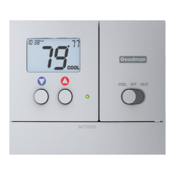
Heat Pump 5+2 Day Programmable
g
Di
ital Thermostat
Installation Instructions
Thank goodness for Goodman.
Model TSTATG2152-2
Control up to 2-Heat & 1-Cool
Battery or System Powered
Backlit Digital Display
Auxiliary Heat Indicator
Fahrenheit or Celsius
Service Filter Indicator
TM
Advertisement
Table of Contents
Troubleshooting

Related Manuals for Goodman TSTATG2152-2


Summary of Contents for Goodman TSTATG2152-2
- Page 1 Air Conditionin g & Heatin g Heat Pump 5+2 Day Programmable ital Thermostat Control up to 2-Heat & 1-Cool Battery or System Powered Backlit Digital Display Auxiliary Heat Indicator Fahrenheit or Celsius Service Filter Indicator Installation Instructions Thank goodness for Goodman.
-
Page 2: Remove Old Thermostat
INSTALLATION INSTRUCTIONS TSTATG2152-2 Contents Page # Safety Warnings Preparation Remove Old Thermostat Battery Replacement Wire Connections Test Operation Troubleshooting Warranty Page 2... -
Page 3: Safety Warnings
INSTALLATION INSTRUCTIONS TSTATG2152-2 Safety Warnings P/N TSTATG2152-2 Follow Installation Instructions carefully. CAUTION DISCONNECT POWER TO THE HEATER - AIR CONDITIONER BEFORE REMOVING THE OLD THERMOSTAT AND INSTALLING WARNING THE NEW THERMOSTAT. CAUTION The two Alkaline “AA” batteries must be replaced at least once every 12 months to ensure proper operation. - Page 4 INSTALLATION INSTRUCTIONS TSTATG2152-2 Preparation Proper installation of the thermostat will be accomplished by following these step by step instructions. If you are unsure about any of these steps, call a qualified technician for assistance. These tools will be required: Flat Blade...
-
Page 5: Remove & Replace Old Thermostat
INSTALLATION INSTRUCTIONS TSTATG2152-2 Remove & Replace Old Thermostat Remove the cover of the old thermostat. If it does not come off easily check for Loosen the screws holding the thermostat base or subbase to the wall, and lift away. Disconnect the wires from the old thermostat. -
Page 6: Battery Replacement
INSTALLATION INSTRUCTIONS TSTATG2152-2 Battery Replacement The batteries are easily accessible from the battery door located on the bottom front of the thermostat (fig. 1). To open the battery slot, pull out on the battery door (fig. 1) and swing down (fig. 2). -
Page 7: Wire Connections
Rev. Valve (Energize to Heat) Rev. Valve (Energize to Cool) Thermal Insulating Sheet A label is provided on the backplate that prevents drafts MODEL: TSTATG2152-2 97061606 4Z95 originating inside the wall from USE SIZE “AA” MADE IN CHINA ALKALINE BATTERIES entering the thermostat. -
Page 8: Sample Wiring Diagrams
OWNER'S MANUAL TSTATG2152-2 Sample Wiring Diagrams 4 Wire, 1 Stage Cooling, 1 Stage Heat-Heat Pump with O reversing valve. Residential Heat Pumps, split systems & package units, with no auxiliary heat. Common wire optional C R Y W G B O... - Page 9 OWNER'S MANUAL TSTATG2152-2 Sample Wiring Diagrams 5 Wire, 1 Stage Cooling, 2 Stage Heat-Heat Pump with O reversing valve. Residential Heat Pumps, split systems & package units, with auxiliary heat. Common wire optional C R Y W G B O...
- Page 10 OWNER'S MANUAL TSTATG2152-2 Sample Wiring Diagrams 4 Wire, 1 Stage Cooling, 1 Stage Heat-Heat Pump with B reversing valve. Residential Heat Pumps, split systems & package units, with no auxiliary heat. Common wire optional C R Y W G B O...
- Page 11 OWNER'S MANUAL TSTATG2152-2 Sample Wiring Diagrams 5 Wire, 1 Stage Cooling, 2 Stage Heat-Heat Pump with B reversing valve. Residential Heat Pumps, split systems & package units, with auxiliary heat. Common wire optional C R Y W G B O...
-
Page 12: Test Operation
INSTALLATION INSTRUCTIONS TSTATG2152-2 Test Operation Turn on the power to the Heat Pump. On the thermostat, slide the Mode Switch to HEAT. Press the COOLER or WARMER button until the set temperature is 10 degrees above room temperature. The HVAC unit should energize in the heating mode. - Page 13 INSTALLATION INSTRUCTIONS TSTATG2152-2 Test Operation On the thermostat, slide the Mode Switch to COOL. Press the COOLER or WARMER buttons until the set temperature is 10 degrees below room temperature. The HVAC unit should energize in the cooling mode (Page 6 of the Owner’s Manual)
-
Page 14: Troubleshooting
INSTALLATION INSTRUCTIONS TSTATG2152-2 Trouble Shooting SYMPTOM: The slide switches on the thermostat are very difficult to move. CAUSE: The backplate of the thermostat is screwed too tightly into a wall that is not perfectly flat. REMEDY: Loosen the screws holding the thermostat into the wall. - Page 15 FOR HOME OR OFFICE USE 4Z95 Air Conditionin g & Heatin g Goodman Manufacturing Company, L.P ., reserves the right to discontinue, or change at any time, specifications or designs without notice or without incurring obligations. Copyright © 2009 • Goodman Manufacturing Company, L.P .
-
Page 16: Limited Warranty
No warranty applies to, and no warranty is offered by Goodman on, Goodman is not responsible for: any thermostat ordered over the Internet.