
Related Manuals for Dell Force10 S4820T System


Summary of Contents for Dell Force10 S4820T System
-
Page 1: Getting Started Guide
Dell Force10 S4820T System Getting Started Guide Publication Date: December 2012 Regulatory Model: S4820T... - Page 2 Other trademarks and trade names may be used in this publication to refer to either the entities claiming the marks and names or their products. Dell Inc. disclaims any proprietary interest in trademarks and trade names other than its own.
-
Page 3: Table Of Contents
Rack Mounting Safety Considerations ....Installing the Dell ReadyRails System ....Installing the Switch . - Page 4 Contents IEEE Standards ......Performing the Initial Configuration ... Navigating CLI Modes .
- Page 5 Contents Contents...
- Page 6 Contents Contents...
-
Page 7: About This Guide
About this Guide This document is intended as a Getting Started Guide to get new systems up and running and ready for configuration. For complete installation and configuration information, refer to the documents listed in Table 1-1. Table 1-1. S4820T Documents Information Documentation Hardware installation and power-up... - Page 8 About this Guide...
-
Page 9: Introduction
For information about how to configure and monitor switch features, refer to the User’s Configuration Guide, which is available on the Dell Support website at support.dell.com/support. This document contains the following sections: Hardware Overview •... - Page 10 The S4820T solution is optimized to provide 10Gbps throughput for distances of up to: • 330 feet (100 meters) over Cat6, 6A, and 7 shielded copper cable and Cat6A UTP copper cable • 181.5 feet (55 meters) over Cat6 UTP copper cable Introduction...
-
Page 11: Hardware Overview
Hardware Overview This section contains information about device characteristics and modular hardware configurations for the S4820T switch. The S4820T has the following physical dimensions: 434 x 460 x 43.5 mm (W x D x H). • 17.09 x 18.11 x 1.71 inches (W x D x H). •... -
Page 12: Fans
Fans The S4820T has stock keeping units (SKUs) that support the following configurations. Installation of the fans is done as part of the factory install based on SKU type. The power supply units (PSUs) are to be installed at the customer site (refer to Power Supplies). -
Page 13: Front Panel
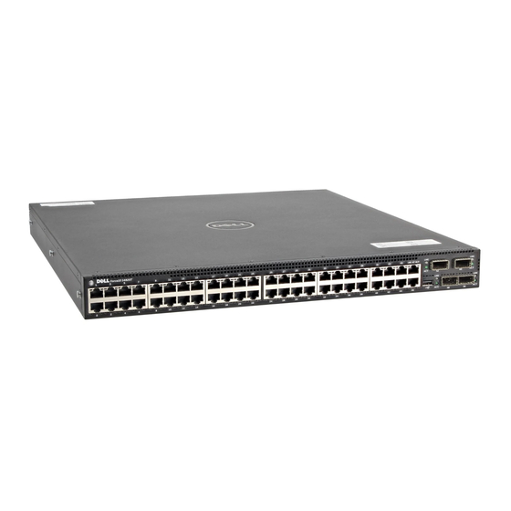
Front Panel Figure 1-2 shows the S4820T front panel. Figure 1-2. S4820T Front Panel 10GBase-T Ports USB 2.0 Port QSFP+ Ports The front panel includes: 48 fixed 10GBase-T and four fixed QSFP+ ports • One USB 2.0 port • The light emitting diodes (LEDs) display for System is on the front panel. NOTE: The fan and power status indicators are on the back panel. -
Page 14: System Status
System Status You can view S4820T status information in several ways, including LEDs and boot menu options. You can also view status information through the command line interface (CLI) show commands and with simple network management protocol (SNMP). For more information about these options, refer to the FTOS Command Line Reference Guide and FTOS Configuration Guide for the S4820T System. - Page 15 Table 1 lists the LED definitions for the S4820T system. Table 1. System LED Displays Feature Detailed Description Comment System LED • Solid blue –Normal I/O side Operation • Blinking blue –Booting • Solid red –Critical system error • Blinking red –Non- critical system error (fan fail, power supply fail) TEMP LED...
- Page 16 Table 1-1. 10GBT Ethernet Port LEDs Feature Detailed Description Link LED • Off – No Link • Solid green –Link on 10Gbps speed • Solid Amber –Link on 100M or 1Gbps speeds Activity LED • Off – No Link • Blinking green – Transmit/Receive is active Table 1-2.
-
Page 17: Installation
Installation Unpacking the Switch Package Contents When unpacking each switch, make sure that the following items are included: One S4820T switch • One RJ-45 to DB-9 female cable • Two sets of rail kits (no tools required) • One PSU •... -
Page 18: Power Supplies
PSU. NOTE: If you use a single PSU, you must install a blank plate in the other PSU slot. Dell Force10 recommends using power supply 1 (PSU1) as the blank plate slot. -
Page 19: Install An Ac Or Dc Power Supply
PSU and the status LED is at the top of the PSU NOTE: If you use a single PSU, you must install a blank plate in the other PSU slot. Dell Force10 recommends using power supply 1 (PSU1) as the blank plate slot. Step... -
Page 20: Rack Mounting The Switch
You may either place the switch on the rack shelf or mount the switch directly into a 19" wide, EIA-310-E- compliant rack (four-post, two-post, or threaded methods). The Dell ReadyRails™ system is provided for 1U front-rack, and two-post installations. The ReadyRails system includes two separately packaged rail assemblies and two rails that are shipped attached to the sides of the switch. -
Page 21: Installing The Dell Readyrails System
Installing the Dell ReadyRails System The ReadyRails rack mounting system is provided to easily configure your rack for installation of your switch. The ReadyRails system can be installed using the 1U tool-less method or one of three possible 1U tooled methods (two-post flush mount, two-post center mount, or four-post threaded). - Page 22 Two-post Flush-mount Configuration: 1 For this configuration, you must remove the castings from the front side of each ReadyRails assembly. Refer to Figure 1-6, item 1. Use a Torx driver to remove the two screws from each front flange ear (on the switch side of the rail) and remove each casting.
- Page 23 4 Repeat this procedure for the second rail. Two-post Center-mount Configuration: 1 Slide the plunger bracket rearward until it clicks into place and secure the bracket to the front post flange with two user-supplied screws. Refer to Figure 1-7, item 1. Figure 1-7.
- Page 24 Four-post Threaded Configuration: 1 For this configuration, you must remove the flange ear castings from each end of the ReadyRails assemblies. Use a Torx driver to remove the two screws from each flange ear and remove each casting. Refer to Figure 1-8, item 1.
-
Page 25: Installing The Switch
Installing the Switch You can mount the switch in the 1U front-rack or 1U two-post (flush and center) configurations. The following is an example of a 1U front-rack configuration. For the 1U two-post (flush and center) configurations, you can slide the switch into the rails in the same manner as the four-post configurations. - Page 26 2 After both switch rails are installed, line them up on the previously mounted Ready-Rails and slide the switch in until it is flush with front of rack. About three inches prior to full insertion, the rail locking feature engages to keep the switch from inadvertently sliding out of the rack and falling.
-
Page 27: Technical Specifications
Technical Specifications Operate the product at an ambient temperature not higher than 40°C. Lithium Battery Caution: There is a danger of explosion if the battery is incorrectly replaced. Replace only with same or equivalent type. Dispose of the batteries according to the manufacturer's instructions. -
Page 28: Power Requirements
Power Requirements Parameter Specifications Power supply 100–240 VAC 50/60 Hz Maximum current draw per system 4 A @ 398.02watts/100vac 2 A @ 398.02watts/200vac Maximum power consumption 398.02 Watts Reliability MTBF 355,178 hours NOTE: The table below represents the DC PSU’s capabilities and does not represent the S4820T operation. -
Page 29: Ieee Standards
IEEE Standards The S4820T switch complies with the following IEEE standards: •802.1AB LLDP •802.1ag Connectivity fault Management •802.1D Bridging, STP •802.1p L2 Prioritization •802.1Q VLAN Tagging, Double VLAN Tagging, GVRP •802.1s MSTP •802.1w RSTP •802.3ab Gigabit Ethernet (1000BASE-T) •802.3ac Frame Extensions for VLAN Tagging •802.3ad Link Aggregation with LACP •802.3ae 10 Gigabit Ethernet (10GBASE-X) •802.3ba 40 Gigabit Ethernet (40GBase-SR4, 40GBase-CR4) on optical ports... - Page 30 Technical Specifications...
-
Page 31: Performing The Initial Configuration
Performing the Initial Configuration Navigating CLI Modes The FTOS prompt changes to indicate the CLI mode. You must move linearly through the command modes, with the exception of the end command which takes you directly to EXEC Privilege mode and the exit command which moves you up one command mode level. - Page 32 To set up the RS-232/RJ-45 console port, follow these steps: Step Task Install an RJ-45 copper cable into the console port. Use a rollover cable to connect the S4820T console port to a terminal server. Connect the other end of the cable to the DTE terminal server. Set the default terminal settings as follows: •...
-
Page 33: Default Configuration
Default Configuration A version of FTOS is pre-loaded onto the S4820T system; however, the system is not configured when you power up for the first time (except for the default host name, which FTOS ). You must configure the system using the CLI. Configure Layer 2 (Data Link) Mode Use the switchport command in INTERFACE mode to enable Layer 2 data transmissions through an individual interface. -
Page 34: Access The System Remotely
Access the System Remotely You can configure the S4820T system to be accessed remotely by Telnet. The system has a dedicated management port and a management routing table that is separate from the IP routing table. To access the system remotely, follow these steps: Step Task Configure an IP address for the management port... -
Page 35: Configure The Management Route
There are two types of enable passwords: • enable password—stores the password in the running/startup configuration using a data encryption standard (DES)-encryption method. • enable secret—stores the running/startup configuration using a stronger, MD5-encryption method. Dell Force10 recommends using the enable secret password. Performing the Initial Configuration... -
Page 36: Create A Port-Based Vlan
To configure the enable secret password, follow this step: Task Command Syntax Command Mode Create a password to enable [password | secret] [level level] CONFIGURATION access EXEC [encryption-type] password Privilege mode. Create a Port-based VLAN The Default VLAN (VLAN 1) is part of the system startup configuration and does not require configuration. - Page 37 To view which interfaces are tagged or untagged and to view which VLAN the interfaces belong, use the show vlan command. To view just the interfaces that are in Layer 2 mode, use the show interfaces switchport command in EXEC Privilege mode or EXEC mode.
-
Page 38: Assign An Ip Address To A Vlan
Assign an IP Address to a VLAN VLANs are a Layer 2 feature. For two physical interfaces on different VLANs to communicate, you must assign an IP address to the VLANs to route traffic between the two interfaces. The shutdown command in INTERFACE mode does not affect Layer 2 traffic on the interface. - Page 39 Printed in the U.S.A. w w w. d e l l . c om | s u p p o r t . d e l l . c om...