Table of Contents
Advertisement
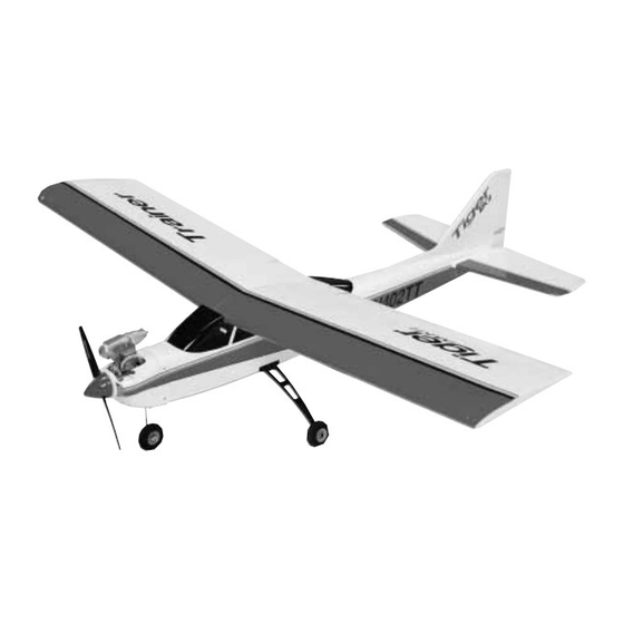
Tiger Trainer MK II
Specifications:
Wingspan:
61"
Length:
51"
Wing area:
675 in
2
Weight:
5-5.5lbs
.40-45
Radio:
4 Channel
Thunder Tiger Trainer MK II Super Combo/Combo Plus/TRTF (TTR4523)
Distributed in North America by Ace Hobby Distributors, Inc.
Phone: (660)-584-7121 • www.acehobby.com • email: service@acehobby.com
This kit is guaranteed to be free from defects in material and workmanship at the date of purchase.
It does not cover any damage caused by use or modification. The warranty does not extend beyond the
product itself and is limited only to the original cost of the kit. By the act of building this user-assembled
kit, the user accepts all resulting liability for damage caused by the final product. If the buyer is not
prepared to accept this liability, it can be returned new and unused to the place of purchase for a refund.
This is not a toy. Assembly and flying of this product requires adult supervision.
Read through this book completely and become familiar with the assembly and flight of this airplane.
Inspect all parts for completeness and damage. If you encounter any problems, call 660-584-6724 for help.
Assembly Manual
116 W. 19th ST, Higginsville, MO 64037
Warranty
Notice: Adult Supervision Required
1
99211/JE6131
Advertisement
Table of Contents

Related Manuals for THUNDER TIGER Tiger Trainer MK II


Summary of Contents for THUNDER TIGER Tiger Trainer MK II
- Page 1 5-5.5lbs Engine: .40-45 Radio: 4 Channel Thunder Tiger Trainer MK II Super Combo/Combo Plus/TRTF (TTR4523) Distributed in North America by Ace Hobby Distributors, Inc. 116 W. 19th ST, Higginsville, MO 64037 Phone: (660)-584-7121 • www.acehobby.com • email: service@acehobby.com Warranty This kit is guaranteed to be free from defects in material and workmanship at the date of purchase.
- Page 2 Notes...
- Page 3 The servos and GP-42 engine are included and installed. Super Combo: If you have the Super Combo version, it will only take you a few minutes to get your Tiger Trainer MK II ready for flight plus no tools or glue are required for completion. Complete radio system and GP-42 engine are included and installed.
- Page 4 PARTS DRAWINGS ORDER BY BAG NUMBER ONLY INDIVIDUAL PARTS NOT AVAILABLE AS6052 Wing Set Aileron Servo Tray (1) Wing Protector (2) Left Wing (1) Retaining Screw (1) Plywood Wing Joiner Right Wing (1) Torque Rod Horn (2) AS6053 Tail Feathers PE0005 Decal Set Retainning Screw (2) Stabilizer/Elevator (1)
- Page 5 PARTS DRAWINGS ORDER BY BAG NUMBER ONLY INDIVIDUAL PARTS NOT AVAILABLE PE0003 Cowl Set PE0002 Window Set Rear Window (1) Windshield (1) Left Cowl (1) Right Cowl (1) PE0004 Hardware Set 3150 Control Horn Set 2mm Hex Nut (2) 3mm Hex Nut (2) Allen Wrench (1) Control Horn (3) Nut Plate (3)
- Page 6 ASSEMBLY I. IF YOU HAVE A SUPER COMBO: Skip to Section IV: ASSEMBLY on page 9. II. IF YOU HAVE A COMBO PLUS: Before performing the final assembly steps, it is necessary to install your receiver and battery pack in the airplane, following your radio system’s instructions.
- Page 7 ASSEMBLY 5. Position the engine so the thrust washer is 4 1/4” from the fire- wall. Making sure the engine is square on the mount, mark the four hole positions on the beams with a pencil. Remove the engine and 8.
- Page 8 ASSEMBLY Z-bend elevator servo to elevator receiver to rudder rudder servo throttle servo EZ connector 2. Hooking your servos to the link- allen wrench age is done according to the above drawing. The pushrods are secured to 11. Complete the spinner installation. Loosen the prop nut and set screw the servo wheels or arms with “z”...
- Page 9 ASSEMBLY IV. ASSEMBLY A. Secure the main landing gear The main landing gear is secured by a “twist ‘n lock” system. Simply put the landing gear into position on the belly of the airplane then rotate the thumb tab 1/4 turn clockwise until it snaps into the groove.
- Page 10 RADIO CHECK 3-3/4" 1/2" 1/2" down elevator up elevator pick up model at arrows to above the fuel tank if you need to. If the plane’s nose drops dra- matically, add a little weight to the tail as a remedy. Stick-on weights 3/8"...
- Page 11 FLYING NOTE: If you get these fuel lines mixed up, look down into the GETTING ORIENTED engine compartment and observe the fuel tank. The fuel line going to the lowest part of the tank is the “fuel” line; it goes to the carb. The We recommend that you find a large smooth and clear surface to other line that goes to the upper part of the tank is the “vent”...
- Page 12 the required control movements to get the plane back on the correct IX. REPAIR flight path. If you run out of time or flying space and realize the plane is going to hit something (ground, tree, etc), pull the throttle back to In the event of a minor mishap, the MKII usually can be repaired.