
Related Manuals for Ariston SOLARcomfort


Summary of Contents for Ariston SOLARcomfort
- Page 1 SOLARcomfort Solar Hot Water Systems Installation Instructions 2 & 3 Collector Sets LEAVE THESE INSTRUCTIONS WITH THE END USER Country of Destination GB/IE...
-
Page 2: Table Of Contents
TABLE OF CONTENTS 5.15 T ..... 19 GENERAL INFORMATION ....2 HREE OLLECTOR CHEMATIC 5.16 F ........20 1.1 G ......... 2 IXING TRAPS UARANTEE 5.17 R ........21 1.2 S ....... 2 YPES YSTEM ONTENTS 5.18 C ......22 1.3 S .... -
Page 3: General Information
The SOLARcomfort Collectors are guaranteed for 5 years against UARANTEE manufacturing defect - see terms and conditions of guarantee on back page. 1.2 S The complete SOLARcomfort solar water heating system is supplied in YSTEM ONTENTS the following consignments:- 1. 800201... -
Page 4: Solar Comfort
UK. However, the savings made will depend on local climate, installation characteristics and the household’s domestic hot water requirements. It is important that the SOLARcomfort system is correctly sized for the local climate condition and the householders requirements. 1.5 L... - Page 5 Roof mounted collectors (two collector system shown) Air vent Energy Monitoring Sensor S4 (option) Temperature Sensor S1 Ariston ITSI 210/300 twin coil cylinder AST 100 Controller PR Valve Pump group Temperature Expansion Sensor S3 vessel Upper coil heated by boiler...
-
Page 6: Safety
TYFOCOR LS Heat Transfer Fluid. Although non-toxic it should not be swallowed. Refer to label on its container for storage and safety information. A detailed technical specification is available from Ariston on request. Caution SOLARcomfort should be installed and commissioned by approved contractors. -
Page 7: Technical Data
TECHNICAL DATA COLLECTORS Weight - each - empty 38kgs Total surface area - each 2m² Aperture area - each 1.83m² Absorber area - each 1.76m² (evaluated according to EN12975:2001) Capacity - each 1.5l Maximum operating pressure 6Bar Pressure loss 10mbar Output - each 100l/h *The stagnation temperature was calculated... -
Page 8: Ist For
3.2 C Listed below are all the components required to fit the collectors for the OMPONENT IST FOR SOLARcomfort 2 collector system. OLLECTOR YSTEM Roof Fixing Kit (cardboard tube) Collector brass fitting kit Flexible connecting kit i r c i t p... -
Page 9: Ist For
Listed below are all the components required to fit the collectors for the 3.3 C OMPONENT IST FOR SOLARcomfort 3 collector system. OLLECTOR YSTEM Roof Fixing Kit (cardboard tube) Collector brass fitting kit Flexible connecting kit i r c i t p... -
Page 10: Collector Dimensions
3.4 C OLLECTOR IMENSIONS . 3.4 OLLECTOR IMENSIONS... -
Page 11: Fixing Strapsd
3.5 F IXING TRAPS IMENSIONS LONG SHORT . 3.5 IXING TRAP IMENSIONS... -
Page 12: Regulations & Standards
REGULATIONS & SOLARcomfort hot water heating systems should be installed in compliance with the following standards and regulations. STANDARDS 4.1 W Water Supply (Water Fittings) Regulations 1999 / www.wras.co.uk ATER EGULATIONS These regulations (bye-laws in Scotland) ensure a good supply of wholesome water and that only approved materials, pipes and fittings are used to convey water. -
Page 13: British & European
Connection of thermal solar heating systems 4.4 B & E RITISH UROPEAN TANDARDS EN 12976: Thermal solar heating systems and their components (prefabricated systems). ENV 12977: Thermal solar heating system and their components (bespoke systems). BS5918: Latest version: Solar heating systems for domestic hot water. Installation and equipment of DHW cylinders BS5546: 2000 Specification for installation of hot water supplies for domestic purposes, using gas-fired appliances of rated input not exceeding 70 kW. -
Page 14: Eu Directives
Further details available from: www.europa.eu.int 4.7 EU D IRECTIVES Construction Directive: 89/106/EEC Electromagnetic: 89/336/EEC Low voltage: 73/23/EEC Machinery Directive: 98/37/EC Preventing hot water scalding in bathrooms: using TMVs (IP 14/03). 4.8 O THER PUBLICATIONS DTI testing of solar systems (SP300275 1-3). Review of issues related to active solar heating systems (SP300246). -
Page 15: Installation
INSTALLATION The following topics should be considered prior to installing the SOLARcomfort system. 5.1 T & C In general Solar Thermal Systems tend to be looked upon favourably by OUNTRY LANNING Local Authority Planning Departments, although there are implications for listed buildings and sensitive front elevations in some conservation areas. -
Page 16: Collector Inclination
Collectors mounted on a pitched roof should always be parallel to the tiles 5.7 C OLLECTOR NCLINATION i.e. at the same angle as the roof. There is no exception to this rule. Collectors can be mounted on a flat roof or the ground, for such applications a special inclined angle fixing set is available - see section 7. -
Page 17: Pipework
The installation of pipework must be made in accordance with good 5.11 P IPEWORK plumbing practice, the following points should be considered when installing pipework. Pipe runs should be chosen to give the shortest most direct route to the storage cylinder, with minimum bends. Tight bends should be avoided. -
Page 18: Onfigurations
Two to seven collectors can be connected in series. When more than 5.13 C OLLECTOR seven are installed we recommend the panels are installed in a parallel ONFIGURATIONS configuration. Connection in series is recommended when a limited output and high domestic hot water temperature is required. SERIES Flow Return... -
Page 19: Collector
5.14 T OLLECTOR CHEMATIC Cylinder Collector Air Separator with manual air vent System Pressure Guage Expansion Vessel Pump Module Solar AST 100 Controller Automatic Air Vent Upper Cylinder Temperature Sensor (S3) Flow Temperature Gauge Lower Cylinder Temperature Sensor (S2) Shut Off Valve Collector Temperature Sensor (S1) Circulating Pump System Fill Point (flow) -
Page 20: Chematic
5.15 T HREE OLLECTOR CHEMATIC Cylinder Collector Air Separator with manual air vent System Pressure Guage Expansion Vessel Pump Module Solar AST 100 Controller Automatic Air Vent Upper Cylinder Temperature Sensor (S3) Flow Temperature Gauge Lower Cylinder Temperature Sensor (S2) Shut Off Valve Collector Temperature Sensor (S1) Circulating Pump... -
Page 21: Three Collector S 5.16 Fixing Straps
5.16 F Two types of Fixing Strap are supplied, long and short - for dimensions IXING TRAPS see fig. 3.5A. The construction of the roof, batten spacing and type of tile will determine which of the fixing straps is most suitable for the installation. Where appropriate, an optional rafter bar is available (code: ). -
Page 22: Roof Types
5.17 R YPES INTERLOCKING PROFILED TILES For all profiled tiles, straps should be fixed to align with the troughs in the tiles as opposed to the peaks, as shown. FLAT TILE / SLATES Bend the fixing strap to ensure a secure fixing on the rafter. -
Page 23: Collector Fixings
The two aluminium collector support rails are bolted directly to the roof 5.18 C OLLECTOR IXINGS fixing straps. Collector bottom brackets hook over the rails on the front edge of the IMPORTANT collectors to prevent the collectors sliding down. After installation check all clamp nuts The extruded section of the support rails is designed to accept M8 hexagon are tight. -
Page 24: Rocedure
Fix lower fixing straps to rafters using the Ø6 x 50 screws provided, 5.19 C OLLECTOR ITTING three screws minimum per strap. Rafters must be sound and screws ROCEDURE must penetrate the rafters by at least 45mm. Two straps for 2 Collectors, three straps 3 Collectors. Slide bolts along one of the support rails to align with lower fixing straps. - Page 26 Approximate positions...
- Page 27 For three collector system repeat No.11 to No. 17. IMPORTANT Tighten all bolts...
- Page 28 Flow shown...
-
Page 29: Commissioning & Servicing
3. ½” to 3/8” Reducer 4. ½” Thermostat Pocket 5. Isolating Valve 6. Collector Temperature Sensor (S1) and Cable 7. Flexible Pipe . 5.20 OLLECTOR ONNECTION YPICAL COMMISSIONING Commissioning and servicing instructions are detailed in the associated SOLARcomfort Pump Group Instructions. AND SERVICING... -
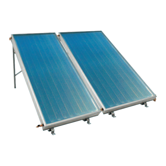
Page 30: Flat Roof/Ground Mounting
7. FLAT ROOF/GROUND Collectors can be mounted on a flat roof or on any prepared flat surface using the Flat Roof/Ground mounting kit. MOUNTING KIT Product Code 3820011 - 2 Collector Kit Product Code 3820012 - 3 Collector Kit 7.1 C OMPONENT i r c i t p... -
Page 31: Angle Of Inclination 7.3 Collector Orientation 7.4 Dimensions
In the unlikely event that peak winter operation (October – March) is required, the inclination should be equal to the latitude of the location, increased by up to 10°, this will encourage absorption when the sun is low over the horizon. In the UK this could result in an angle of 50° - 75°, however it is not practical to install the collector at an angle greater than 60°. -
Page 32: Flat Roof Condition 7.6 Ground Preparation 7.7 Assembly
When the collectors are to be mounted on the ground a suitable base 7.6 G ROUND REPARATION should be provided. A suggested construction is shown in Fig. 7.5a. The frame should be fixed to the base with M10 Bolts (not supplied). On very exposed sites further bracing is recommended. - Page 33 NOTES...
- Page 34 TERMS AND CONDITIONS OF GUARANTEE The SOLARcomfort Collectors are guaranteed for 5 years against manufacturing defect. Please read these terms and conditions which are in addition to any terms and conditions detailed in this book or any registration card supplied with your appliance.