JVC Studio Kit KA-F5602U Instructions Manual
Studio kit/studio sdi kit
Hide thumbs
Also See for Studio Kit KA-F5602U:
- Instructions manual (24 pages) ,
- Instruction manual (47 pages)
Table of Contents
Advertisement
Quick Links
STUDIO KIT
STUDIO SDI KIT
KA-F5602U
KA-F5603U
This instructions book is made from 100 %
recycled paper.
Thank you for purchasing this JVC product.
Before operating this unit, please read the
instructions carefully to ensure the best
possible performance.
BREAKER
PROMPTER
OUTPUT
RM
DC INPUT
INSTRUCTIONS
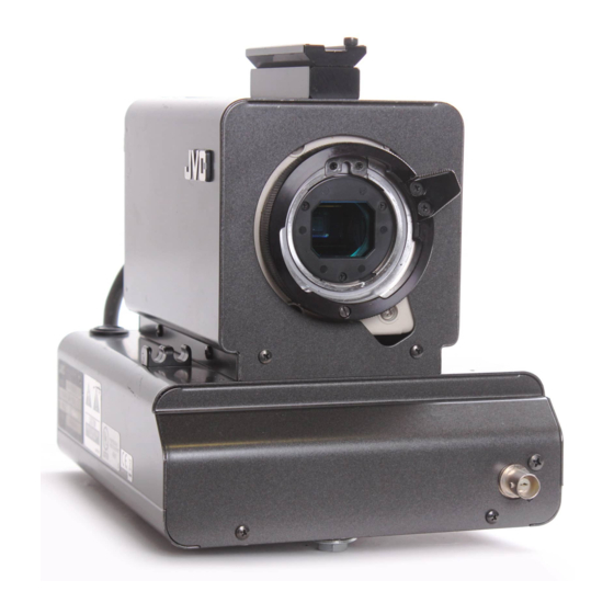
*Illustration with optional lens
and viewfinder attachments.
For Customer Use:
Enter below the Serial No. which is
located on the cabinet. Retain this
information for future reference.
Model No. KA-F5602U/KA-F5603U
Serial No.
LWT0176-001B
Advertisement
Chapters
Table of Contents

Related Manuals for JVC Studio Kit KA-F5602U


Summary of Contents for JVC Studio Kit KA-F5602U
- Page 1 STUDIO SDI KIT KA-F5602U KA-F5603U This instructions book is made from 100 % recycled paper. Thank you for purchasing this JVC product. Before operating this unit, please read the instructions carefully to ensure the best possible performance. BREAKER *Illustration with optional lens...
- Page 2 1. Read all of these instructions. 2. Save these instructions for later use. 3. All warnings on the product and in the operating instructions should be adhered to. 4. Unplug this appliance system from the wall outlet before cleaning. Do not use liquid cleaners or aerosol cleaners.
- Page 3 ● Consult the dealer or an experienced radio/TV technician for help. CAUTION CHANGES OR MODIFICATIONS NOT APPROVED BY JVC COULD VOID USER’S AUTHORITY TO OPERATE THE EQUIPMENT. THIS DEVICE COMPLIES WITH PART 15 OF THE FCC RULES. OPERATION IS SUBJECT TO THE...
- Page 4 SAFETY PRECAUTIONS (FOR EUROPE) WARNING: TO REDUCE THE RISK OF FIRE OR ELECTRIC SHOCK, DO NOT EXPOSE THIS APPLIANCE TO RAIN OR MOISTURE. This unit should be used with 12 V DC only. CAUTION: To prevent electric shocks and fire hazards, do NOT use any other power source.
- Page 5 This equipment is in conformity with the provisions and protection requirements of the corre- sponding European Directives. This equipment is designed for professional video appliances and can be used in the following environments: 5 Residential (including both of the location type class 1 and 2 found in IEC 1000-2-5) 5 Commercial and light industrial (including, for example, theatres) 5 Urban outdoors (based on the definition of location type class 6 in IEC 1000-2-5) In order to keep the best performance and furthermore for electromagnetic compatibility we...
-
Page 6: Main Features
Thank you for purchasing this KA-F5602U / KA-5603U Studio Kit. This product is a kit meant for converting JVC’s KY-F560 video camera into a studio camera. Model designation may differ depending on whether the Studio Kit is equipped with a SDI (Serial Digital Interface) terminal. -
Page 7: Table Of Contents
Contents Getting Started Accessories ... 8 Related Products used in Conjunction with this Unit ... 8 Precautions ... 9 Regarding Gain-lock Signal and adjustment of System Phase ... 9 Part Names and Functions ... 10 Installation System ... 13 Installation Procedures ... 14 Mounting KY-F560 Camera on this Unit ... -
Page 8: Getting Started Accessories
Getting Started Accessories Studio Kit main body BREAKER PROMPTER OUTPUT DC INPUT Relay board Related Products used in Conjunction with this Unit ● Color video camera ... KY-F560 ● 4-inch Viewfinder ... VF-P400 ● Remote Control Unit ... RM-P210 ● Intercom Headset ... KA-310U ●... -
Page 9: Precautions
Precautions In order to ensure that this unit could serve you longer, avoid storing or using it at the following places. Extremely hot or cold places Places with strong vibration Dusty places High humidity places In the vicinity of strong noise sources Do not subject this unit to strong vibration or impact when installing or moving it. -
Page 10: Part Names And Functions
“SYSTEM” menu screen on the KY- F560. (☞ page 21) [INTERCOM] Intercom Input Terminal (XLR 5 Pin) Input terminal for intercom headset. JVC Headset KA-310U can be connected here. [INCOM LEVEL] Intercom Receiver Volume Use for adjusting the intercom headset re- ceiver volume level. - Page 11 [DYNAMIC] : Choose this setting if dy- namic type microphone is to be used. If JVC Headset KA-310U is to be used, choose the [CARBON] setting. [CALL] Call Button Press this button to send call signal to the remote control unit operator if intercom headset is not in-use.
- Page 12 ON again to put this unit in the operating status. If this unit still does not function properly, consult your JVC-authorized dealer. & Screw Holes for Mounting Tripod...
-
Page 13: Installation System
Installation System Studio kit/Studio SDI kit KA-F5602U/KA-F5603U Lens PROMPTER OUTPUT [PROMPTER OUTPUT] connector Monitor Tripod TP-P300 Dolly TP-P205 ● Please refer to KY-F560 instruction manual for details on the lens and lens remote control. ● The 26 Pin camera cable used should be less than 100 m. ●... -
Page 14: Installation Procedures
Installation Installation Procedures 1. Mounting KY-F560 Camera on this Unit. 2. Mounting the Lens onto the Camera. 3. Mounting this Unit onto the Tripod. 4. Mounting VF-P400 4-inch Viewfinder on this Unit. Mounting KY-F560 Camera on this Unit Camera mounting bracket Camera mounting frame Preparations to be done on KY-F560 cam- era. - Page 15 Mounting KY-F560 Camera on this Unit (continued) Mounting bracket Screw Ç Camera mounting frame Slot Relay board Place the camera on top of the camera mounting frame and use the screw Ç pro- vided to secure the camera to the base of the frame.
-
Page 16: Mounting The Lens Onto The Camera
Please refer to KY-F560 instruction manual on mounting the lens. ● When using the under-mentioned types of lens, lens cable ECE-R22 which is sold sepa- rately must be used. (Please consult your local JVC authorized service agent for details of the cable to be used.) S17 x 6.6 BRM(FUJINON) -
Page 17: Mounting Vf-P400 4-Inch Viewfinder On This Unit
Mounting VF-P400 4-inch Viewfinder on this Unit Viewfinder Cable Viewfinder terminal Loosen the viewfinder lock lever by turning it anti-clockwise. Slide the viewfinder forward along the viewfinder holder guide on top of this unit. Turn the viewfinder lock lever clockwise to lock it. Plug the viewfinder cable connector into this unit’s viewfinder terminal. -
Page 18: Connecting Rm-P210 Connecting To Remote Control Unit Rm-P210
Connecting RM-P210 Connecting to Remote Control Unit RM-P210 Headset KA-310U TALLY CALL FULL AUTO MENU/SHUTTER GAIN SHUTTER STEP HIGH SHUTTER VARIABLE BARS MENU PUSH-ON PUSH-ON GAIN INTERCOM DOWN DOWN LEVEL Remote control unit RM-P210 Monitor [PROMPTER OUTPUT] terminal Connection Switch off RM-P210 power supply before attempting the connection. ●... - Page 19 Switch setting ● Set the [CARBON/DYNAMIC] switch according to the type of intercom headset microphone to be used. (If JVC Headset KA-310U is connected, choose the [CARBON] setting.)) ● Set the [INCOM MIC ON / OFF] switch depending on whether headset microphone will be used. If the switch is set to [ON], then the headset microphone could be used.
-
Page 20: Notes To Be Taken When Operating Rm-P210
Connecting RM-P210 Notes to be taken when operating RM-P210 When using RM-P210 menu to carry out the setting of KY-F560, some items of RM-P210 menu setting may not be consistent with the operations of KY-F560. RM-P210 Menu Item “PROCESS” screen “KNEE POINT”... -
Page 21: Menu Screen
Menu Screen When KY-F560 camera is mounted on this unit, new menu screens and menu items are added to the original KY-F560 menu screen. The additional new menu screens and menu items will be explained here. Please refer to KY-F560 instruction manual for details on menu screen setting. “SYSTEM”... -
Page 22: Display" Menu Screen
Menu Screen “DISPLAY” Menu Screen Additional new “DISPLAY” menu screens are added. The settings in bold are factory settings. Item “CHARACTER” “F NO.” “SAFETY ZONE” “CENTER MARK” “TALLY” Function/Variables To select whether characters will be displayed in the viewfinder. “OFF” : Characters will not be displayed. -
Page 23: Others
Others Specifications RM Multi-pin connector PROMPTER output SDI output Operating temperature range : –5 °C to 40 °C (Humidity below 80 %) Allowable storage temperature : –20 °C to 60 °C Power supply voltage Power consumption Dimensions Mass Accessories Dimensions (Unit: mm) INCOM MIC CARBON DYNAMIC... - Page 24 MEMO...
- Page 25 スタジオキット スタジオSDIキット 型 KA-F5602U 名 KA-F5603U お買い上げありがとうございます。 ●ご使用の前にこの「取扱説明書」と「安全上のご注意」 を良くお読みのうえ、正しくお使いください。 特に、「安全上のご注意」は必ずお読みいただき安全 にお使いください。お読みになったあとは、保証書と 一緒に大切に保管し、必要なときにお読みください。 ●製造番号は品質管理上、重要なものです。お買いあげ の際は本機に製造番号が正しく記載されているか、ま たその製造番号と保証書に記載されている製造番号が 一致しているかを、お確かめください。 イラストは、別売のレンズ・ BREAKER ビューファインダーを取り付 PROMPTER けた例です。 OUTPUT DC INPUT 私たちは環境・資源をたいせつにしています。 この取扱説明書はエコマーク認定の再生紙 (古紙100%)を使用しています。 取扱説明書...
- Page 26 スタジオキット KA-F5602U / KA-F5603U を お買い上げいただきありがとうございます。 この商品は、 当社カラービデオカメラKY-F560をスタジオカメラとして使用するためのキッ トです。 SDI(Serial Digital Interface)出力端子の有無により型名が異なります。 KA-F5602U KA-F5603U 主な特長 ● アナログ26Pカメラコネクター装備 別売のリモートコントロールユニットRM-P210に接続し、 最大100 mまでの範囲で本機 をコントロールできます。 この場合、 カメラへの電源はリモートコントロールユニットから 供給されますので、 カメラ用として別電源を用意する必要はありません。 ● 多系統な出力 26Pカメラコネクターからはコンポジット信号の他、 RGBコンポーネント、 Y/Cb/Crコン ポーネントまたはYCセパレート信号のいずれかを出力します。 ( メニュースイッチにて選 択します。 ) ● 4型ビューファインダーVF-P400装着可能 ● インカム端子装備 ヘッドセットを使用することにより、 リモートコント−ロールユニットのオペレーターと のコミニュケーションが可能となります。...
- Page 27 目次 はじめに 付属品をご確認ください ... 28 本機を使用するための関連商品 ... 28 正しくお使いいただくためのご注意 ... 29 ゲンロック信号およびシステム位相調整について ... 29 各部の名称と働き ... 30 取付 システム ... 33 取り付けの手順 ... 34 本機にKY-F560カメラを取り付ける ... 34 カメラにレンズを取り付ける ... 36 本機を三脚に取り付ける ... 36 本機に4型ビューファインダーVF-P400を取り付ける ... 37 RM-P210接続 リモートコントロールユニットRM-P210を接続する ... 38 RM-P210操作時のご注意...
-
Page 28: 付属品をご確認ください
はじめに 付属品をご確認ください スタジオキット本体 BREAKER PROMPTER OUTPUT DC INPUT 中継ボード 本機を使用するための関連商品 ● カラービデオカメラ ... KY-F560 ● 4型ビューファインダー ... VF-P400 ●リモートコントロールユニット ... RM-P210 ● インターカム用ヘッドセット ... KA-310U ● 26Pinカメラケーブル ... VC-P110 (5 m) ● リモートコントロールユニットRM-P210を使用しない場合、 AC電源は下記のものを使用 してください。 AC電源 ... AA-P250 ※詳細は33ページの 「システム」 をご覧ください。 スクリュー1本:KY-F560カメラをスタジオ... -
Page 29: 正しくお使いいただくためのご注意
正しくお使いいただくためのご注意 本機を長い間ご使用いただくために、 次の ような場所での使用および保管は避けてく ださい。 極端に暑い所や寒い所 激しい振動のある所 ほこりの多い所 湿気の多い所 強いノイズの発生源の近く 設置、 移動時に強い振動や衝撃を与えない でください。 本機に電源を入れた状態で、 カメラケーブル コネクターを抜き差ししないでください。 電源は指定された電源をお使いください。 RM-P210より供給またはAA-P250 節電のため、 使用しないときは電源を切っ てください。 トランシーバーや携帯電話を本機の近くで 使用すると、 インカムのスピーカーにノイ ズが入ったり画面にノイズが出ることがあ りますが、 これは故障ではありません。 ゲンロック信号およびシステム位相調整について RM-P210リモートコントロールユニットと のシステムで使用した場合、 ゲンロック信号 はKY-F560カメラおよびRM-P210のどち らからでも入力できます。 ただし、 KY-F560とRM-P210の両方にゲ ンロック信号を入力すると、 画面が乱れます。 システム位相調整は、 ゲンロック信号が入力 された機器側で行なってください。 また、... -
Page 30: 各部の名称と働き
はじめに 各部の名称と働き INTERCOM [RM]RMマルチピンコネクター (26ピン) 26ピンカメラケーブルを用いて、 リモー トコントロールユニットRM-P210と接 続します。 また、 このコネクターを介して、 リモート コントロールユニットから本機およびカ メラに電源が供給されます。 メモ カメラ映像信号はコンポジット信号の 他にRGBコンポーネント、 Y/Cb/Crコ ンポーネント、 YCセパレート信号のい ずれかをRM-P210の出力端子から出 力します。 出力信号は、 K Y - F 5 6 0 の "SYSTEM"メニュー画面の"OUTPUT" 項目で選択します。 ( ☞41ページ) [INTERCOM]インターカム入力端子 (XLR5ピン) インターカム用ヘッドセットの入力端子 です。 当社製ヘッドセットKA-310Uを接 続できます。... - Page 31 各部の名称と働き (つづき) [INCOM MIC]インターカム用マイク [CARBON/DYNAMIC]スイッチ インターカム用ヘッドセットのマイク型 式を選択します。 [CARBON] : カーボン型マイクの場 合、 この設定にします。 [DYNAMIC] : ダイナミック型マイクの 場合、 この設定にします。 ※当社製ヘッドセットKA-310U接続時 には、 [CARBON]に設定してください。 [CALL]コールボタン インターカム用ヘッドセットを用いない で、 リモートコントロールユニットのオペ レーターにコール信号を送るとき、 このボ タンを押します。 このボタンを押しているいる間、 リモート コントロールユニットにコール信号を送 り、 リモートコントロール ユニットの [TALLY]ボタンが点滅します。 ボタンか ら指を離すと、 コール信号の送信を止め、 リ モ ー ト コ ン ト ロ ー ル ユ ニ ッ ト の [TALLY]ボタンが消灯します。...
- Page 32 はじめに 各部の名称と働き (つづき) [PROMPTER OUTPUT]プロンプター 出力端子 (BNC) リモートコントロールユニットの[AUX] 入力端子に入力された信号 (プロンプター ビデオ信号) をRMマルチピンコネクター を介して、 この端子から出力します。 コンポジット信号で出力します。 ビデオモ ニタ−に接続します。 [DC INPUT]DC電源入力端子 (XLR4ピン) リモートコントロールユニットR M - P210を接続しない場合、 この端子にDC 電源を入力します。 電源は、 AA-P250を 使用してください。 PROMPTER OUTPUT & [BREAKER]ブレーカースイッチ 消費電力が容量オーバーしたとき、 ブレー カーが切れます。 ブレーカーが切れた場合 は、 何か異常があって定格電力を越えてい ないかを確認した後、 異常がなければブ レーカーを押し、...
-
Page 33: システム
取付 システム Studio kit / Studio SDI kit KA-F5602U/KA-F5603U Lens PROMPTER OUTPUT [PROMPTER OUTPUT] connector Monitor Tripod TP-P300 Dolly TP-P205 ● レンズおよびレンズリモコンはKY-F560取扱説明書をご覧ください。 ● 26Pin カメラケーブルは、 100 m以内でお使いください。 ● リモートコントロールユニットRM-P210を使用したとき、 電源は26Pinカメラケーブル を介してRM-P210から供給されます。 リモートコントロールユニットRM-P210を使用 しない場合、 電源はAA-P250 AC power adapterを使用してください。 Viewfinder VF-P400 Color video camera KY-F560 BREAKER DC INPUT... -
Page 34: 取り付けの手順
取付 取り付けの手順 1. 本機にKY-F560カメラを取り付けます。 2. カメラにレンズを取り付けます。 3. 本機を三脚に取り付けます。 4. 本機に4型ビューファインダー (VF-P400)を取り付けます。 本機にKY-F560カメラを取り付ける カメラ取付ブラケット カメラ取付用フレーム KY-F560カメラに対する取付の準備作 業を行います。 Å スクリュー ● KY-F560カメラにレンズが付いてい る場合は、 レンズを外しておきます。 ● カメラ取付ブラケットは、 カメラの底面 に取り付けた状態にします。 スロットカバー ● カメラ背面部のスクリュー し、 スロットカバーを外します。 本機のスクリュー 取付用フレームを引き出します。 ı スクリュー Å 2本を外 ı 2本をゆるめ、 カメラ... - Page 35 本機にKY-F560カメラを取り付ける (つづき) 取付ブラケット Ç スクリュー カメラ取付用フレーム スロット部 中継ボード カメラ取付用フレームにカメラを置き、 本 機に付属のスクリュー ム底面部にカメラを固定します。 カメラ底面部の取付ブラケットのネジ孔 を用いて固定します。 カメラを取り付けたフレームを本機に挿 入し、 上記手順 ı 2本を用いて本機に固定します。 メモ ● カメラのレンズマウントキャップは 事前に取りはずしてください。 ● カメラ取付フレームを本機に挿入す るとき、 カメラ前面部のレンズ固定用 ı スクリュー 本機の中継ボードをカメラ背面のスロッ Ç ト部に挿入し、 上記手順 スクリュー リュー す。 メモ 中継ボードは奥まで確実に挿入してくだ さい。 Ç を用いてフレー...
-
Page 36: カメラにレンズを取り付ける
取付 カメラにレンズを取り付ける レンズの取付方法は、 KY-F560取扱説明書をお読みください。 ● 下記のズームレンズを使用する場合は、 別売のレンズケーブルECE-R22が必要です。 ( ケー ブルの詳細は、 最寄りのビクターサービス窓口にご相談ください。 ) S17 x 6.6 BRM (FUJINON) YH16 x 7K12U (CANON) ● レンズケーブルは本機のケーブルクランプに固定してください。 ECE-R22レンズケーブル 本機を三脚に取り付ける 本機底面部のネジ孔を使って三脚に取り付けます。 複数のネジ孔を備えていますので、 本機の バランスがとれる位置のネジ孔を使って三脚に取り付けてください。 ケーブルクランプ レンズケーブル ネジ孔... -
Page 37: 本機に4型ビューファインダーVf-P400を取り付ける
本機に4型ビューファインダーVF-P400を取り付ける ビューファインダー ケーブル ビューファインダー端子 ビューファインダーのロックレバーを反時計方向に回してロックレバーをゆるめます。 ビューファインダーを本機上面部のビューファインダーホルダーのガイドに沿わせて、 前 方にスライドさせます。 ビューファインダーのロックレバーを時計方向に回して固定します。 ビューファインダーケーブルのコネクターを本機のビューファインダー端子に接続しま す。 メモ KY-F560の"SYSTEM"メニュー画面の"ASPECT RATIO"項目を"16 : 9"に設定したと き、 ビューファインダーVF-P400には縦長の映像が表示されます。 4 型ビューファインダー VF-P400 ロックレバー ビューファインダーホルダー... -
Page 38: Rm-P210接続
RM-P210接続 リモートコントロールユニットRM-P210を接続する ヘ ッ ド セ ッ ト KA-310U TALLY CALL FULL AUTO SHUTTER BARS GAIN INTERCOM LEVEL リモートコントロールユニット RM-P210 モニタ− 接 続 接続はRM-P210 の電源を切ってから行なってください。 ● 本機のRMマルチピンコネクターとRM-P210を26Pinカメラケーブルで接続します。 カ メラケーブル長は100 m以内でお使いください。 ● インターカム用ヘッドセットを使用する場合は、 [INTERCOM]端子にヘッドセットKA- 310Uを接続します。 ● RM-P210からのプロンプタービデオ(RM-P210の[AUX VIDEO INPUT]端子の入力信 号) を確認する場合は、 本機前面部の[PROMPTER OUTPUT]端子とモニタ−をBNCケー ブルで接続します。... - Page 39 リモートコントロールユニットRM-P210を接続する (つづき) GENLOCK IN VIDEO OUT DC IN POWER 本機背面 SEE INST INCOM MIC CARBON DYNAMIC INTERCOM INCOM LEVEL CALL [CARBON/DYNAMIC] スイッチ [INCOM MIC ON/OFF]スイッチ 操 作 ● カメラリモートコントロールユニットの[POWER]スイッチを[ON]にします。 [POWER] スイッチを[ON]にしてから、 約30秒程度経過後、 カメラリモートコントロールユニットの 操作が可能になります。 メモ カメラリモートコントロールユニットは[POWER]スイッチが[ON]になった後、 30秒 間、 本機との通信が正常に動作するよう準備します。 GENLOCK IN VIDEO OUT DC IN POWER...
-
Page 40: Rm-P210操作時のご注意
RM-P210接続 RM-P210操作時のご注意 RM-P210のメニュー操作でKY-F560カメラを設定するとき、 一部のメニュー項目におい て、 RM-P210のメニュー設定表示とKY-F560の動作が一致しない点があります。 RM-P210メニュー 項 目 "PROCESS"画面 "KNEE POINT" (オートニーOFF時の ニーポイント設定) "GAMMA LEVEL" (ガンマーカーブの補正) "OPERATION"画面 "V,GAIN STEP" (バリアブルゲインのス テップ設定) KY-F560の動作 可変値 ニーポイントは次のように変わります。 NORMAL: 100 % (最大レベル) NORMAL : 80 % (最小レベル) マイナス側の2ステップで5 %ずつレベ ルが変わります。 プラス側 (1∼10) に設定しても、 ニーポ イントは変化しません。... -
Page 41: System"メニュー画面
メニュー画面 KY-F560カメラを本機に装着すると、 KY-F560のメニュー画面に新規のメニュー項目やメ ニュー画面が追加されます。 ここでは、 新規追加のメニュー項目およびメニュー画面の内容を説明します。 メニュー画面の設定方法については、 KY-F560の取扱説明書をご覧ください。 "SYSTEM"メニュー画面 "SYSTEM"メニュー画面に下記の項目が追加されます。 太字は工場出荷設定 項 目 "OUTPUT" RMマルチピンコネクターからはコンポジットビデオ信号の他に、 もう一種類の映像信号を出力することができます。 その出力信号を 選択します。 "Y/Cb/Cr" "RGB" "Y/C" "SYNC ON G" RGBコンポーネント信号のG信号にSYNC信号を付けるかどうか を選択します。 この項目は、 "OUTPUT"項目の設定を"RGB"にしたときのみ設定 できます。 "ON" "OFF" 機能 ・ 可変値 :Y/Cb/Crコンポーネント信号を出力します。 :RGBコンポーネント信号を出力します。 "SYNC ON G"項目でG信号にSYNC信号を付け るかどうかを選択できます。 :YCセパレート信号を出力します。... -
Page 42: Display"メニュー画面
メニュー画面 "DISPLAY"メニュー画面 "DISPLAY" メニュー画面が新たに追加されます。 太字は工場出荷設定 項 目 "CHARACTER" "F NO." "SAFETY ZONE" "CENTER MARK" "TALLY" ビューファインダーにキャラクター表示するかどうかを選択しま す。 "OFF" :キャラクターを表示しません。 "ON" :キャラクターを表示します。 次の項目でキャラクター表示の有無を個別に設 定できます。 ※ この項目を"ON"に設定しても、 個別のキャラクター項目の設定 を"OFF"に設定すると、 そのキャラクターは表示されません。 レンズアイリスのF値をビューファインダーに表示するかどうか を選択します。 "OFF" :表示しません。 "ON" :表示します。 ビュ−ファインダ−へのセイフティゾ−ン表示の有無および表示 スタイルを選択します。 "OFF" :表示しません。 "NORMAL" :アスペクト比4 : 3のセイフティゾ−ンを表示し ます。... -
Page 43: 保証とアフターサービス
その他 保証とアフターサービス 保証書の記載内容ご確認と保存について この商品には保証書を別途添付してあります。 保証書はお買い上げ販売店でお渡ししますの で、 所定事項の記載および記載内容をご確認いただき、 大切に保存してください。 保証期間について 保証期間はお買い上げ日より1年間です。 以後は有償修理となります。 保証書の記載内容によりお買い上げ販売店が修理いたします。 なお、 修理保証以外の補償はいたしかねます。 故障その他による営業上の機会損失は致しません。 その他詳細は保証書をご覧ください。 保証期間経過後の修理について 保証期間経過後の修理については、 お買い上げ販売店にご相談ください。 修理によって機 能が維持できる場合は、 お客様のご要望により有料にて修理いたします。 アフターサービスについてのお問い合わせ先 アフターサービスについてご不明の点は、 お買い上げ販売店または別紙業務機器ビクター サービス窓口案内をご覧の上、 最寄りの業務機器ビクターサービス窓口にご相談ください。 商品廃棄について この商品を廃棄する場合は、 法令や地域の条例に従って適正に処理してください。 修理を依頼されるときは 調子が悪いときは、 この取扱説明書をもう一度ご覧になってお調べください。 簡単な調整 で直ることがあります。 それでも具合が悪いときは、 お買い上げ販売店またはビクター サービスにご相談ください。 • 機種名 : KA-F5602U/KA-F5603U •... - Page 44 その他 仕様 RMマルチピンコネクター:コンポジットビデオ信号出力 PROMPTER出力 SDI出力 使用温度範囲 許容保存温度範囲 入力電源電圧 消費電力 外形寸法 質量 付属品、 添付物 外形寸法図 (単位 : mm) INCOM MIC CARBON DYNAMIC INTERCOM INCOM LEVEL CALL 本機の仕様および外観は、 改善のため予告なく変更することがあります。 (Y/Cb/Cr、 RGB、 YCセパレートのいずれかの出力信号を選択可) :プロンプタ−ビデオ信号出力 (コンポジット信号) :シリアルデジタル映像信号 (SMPTE259M準拠) 0.8 V(p-p), 75 Ω不平衡 (KY-F5603Uのみ) :−5 ℃∼40 ℃ (湿度80%以下) :−20 ℃∼60 ℃...
- Page 45 メモ...
- Page 46 〒192-8620 東京都八王子市石川町2969-2 電話 (0426) 60-7245 © 2004 Victor Company of Japan, Limited お 客 様 ご 相 談 セ ン タ ー フリーダイヤル 0 1 2 0 – 2 8 2 8 – 1 7 携帯電話・PHS・FAXなどからのご利用は ( 0 3 ) 5 6 8 4 - 9 3 1 1 [...
- Page 47 ® is a registered trademark owned by Victor Company of Japan, Limited ® is a registered trademark in Japan, the U.S.A., the U.K. and many other countries. © 2004 Victor Company of Japan, Limited Printed in Japan LWT0176-001B...