Table of Contents
Advertisement
Quick Links
Download this manual
See also:
Instruction Manual
STUDIO KIT
STUDIO SDI KIT
KA-F5602U
KA-F5603U
This instructions book is made from 100 %
recycled paper.
Thank you for purchasing this JVC product.
Before operating this unit, please read the
instructions carefully to ensure the best
possible performance.
BREAKER
PROMPTER
RM
OUTPUT
DC INPUT
INSTRUCTIONS
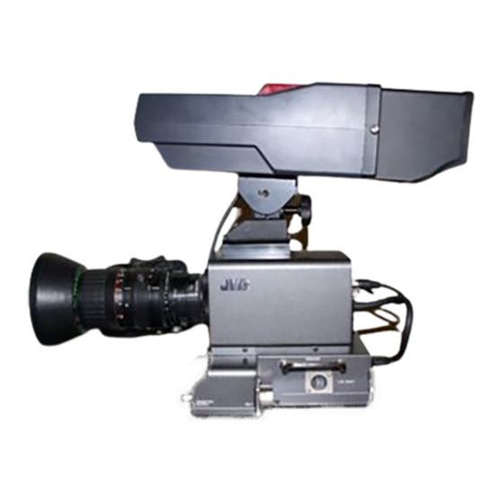
*Illustration with optional lens
and viewfinder attachments.
For Customer Use:
Enter below the Serial No. which is
located on the cabinet. Retain this
information for future reference.
Model No. KA-F5602U/KA-F5603U
Serial No.
LWT0176-001A
Advertisement
Table of Contents

Related Manuals for JVC KY-F560U - 3-ccd Color Camera


Summary of Contents for JVC KY-F560U - 3-ccd Color Camera
- Page 1 Enter below the Serial No. which is located on the cabinet. Retain this information for future reference. Thank you for purchasing this JVC product. Before operating this unit, please read the Model No. KA-F5602U/KA-F5603U instructions carefully to ensure the best possible performance.
- Page 2 1. Read all of these instructions. 2. Save these instructions for later use. 3. All warnings on the product and in the operating instructions should be adhered to. 4. Unplug this appliance system from the wall outlet before cleaning. Do not use liquid cleaners or aerosol cleaners.
- Page 3 CAUTION INFORMATION (F0R CANADA) CHANGES OR MODIFICATIONS NOT APPROVED RENSEIGNEMENT (POUR CANADA) BY JVC COULD VOID USER’S AUTHORITY TO OPERATE THE EQUIPMENT. This Class B digital apparatus complies with THIS DEVICE COMPLIES WITH PART 15 OF THE Canadian ICES-003.
- Page 4 SAFETY PRECAUTIONS (FOR EUROPE) WARNING: TO REDUCE THE RISK OF FIRE OR ELECTRIC SHOCK, DO NOT EXPOSE THIS APPLIANCE TO RAIN OR MOISTURE. This unit should be used with 12 V DC only. CAUTION: To prevent electric shocks and fire hazards, do NOT use any other power source.
- Page 5 This equipment is in conformity with the provisions and protection requirements of the corre- sponding European Directives. This equipment is designed for professional video appliances and can be used in the following environments: 5 Residential (including both of the location type class 1 and 2 found in IEC 1000-2-5) 5 Commercial and light industrial (including, for example, theatres) 5 Urban outdoors (based on the definition of location type class 6 in IEC 1000-2-5) This apparatus is designed for rack mounting or is used close to other apparatus.
- Page 6 Thank you for purchasing this KA-F5602U / KA-5603U Studio Kit. This product is a kit meant for converting JVC’s KY-F560 video camera into a studio camera. Model designation may differ depending on whether the Studio Kit is equipped with a SDI (Serial Digital Interface) terminal.
-
Page 7: Table Of Contents
Contents Getting Started Accessories ......................8 Related Products used in Conjunction with this Unit .......... 8 Precautions ......................9 Regarding Gain-lock Signal and adjustment of System Phase ......9 Part Names and Functions ................10 Installation System ......................13 Installation Procedures ..................14 Mounting KY-F560 Camera on this Unit ............ -
Page 8: Getting Started Accessories
Getting Started Accessories Studio Kit main body Screw - 1 piece: Use for securing KY-F560 camera on the Studio Kit. BREAKER Instructions (this booklet) PROMPTER OUTPUT DC INPUT Relay board Related Products used in Conjunction with this Unit ● Color video camera ......KY-F560 ●... -
Page 9: Precautions
Precautions In order to ensure that this unit could serve Earthing the INTERCOM G(GND) terminal you longer, avoid storing or using it at the is recommended as noises may be induced depending on the intercom headset used. following places. Use only the specified standard length Extremely hot or cold places camera cable. -
Page 10: Part Names And Functions
“SYSTEM” menu screen on the KY- F560. (☞ page 21) [INTERCOM] Intercom Input Terminal (XLR 5 Pin) Input terminal for intercom headset. JVC Headset KA-310U can be connected here. [INCOM LEVEL] Intercom Receiver Volume Use for adjusting the intercom headset re- ceiver volume level. - Page 11 Caution to be used. To avoid causing malfunction, please do If JVC Headset KA-310U is to be used, not touch this terminal except when con- choose the [CARBON] setting. necting cable to it. [CALL] Call Button...
- Page 12 ON again to put this unit in the operating (XLR 4 Pin) status. If this unit still does not function Apply DC power to this terminal if Remote properly, consult your JVC-authorized Control Unit RM-P210 is not going to be dealer. connected. For DC power supply, use AA- &...
-
Page 13: Installation
Installation System Viewfinder VF-P400 AC power adapter AA-P250 VC-710 (5 m) Studio kit/Studio SDI kit KA-F5602U/KA-F5603U Color video camera Lens KY-F560 Headset KA-310U COLOR VIDEO CAMERA KY-F560 BREAKER PROMPTER OUTPUT DC INPUT [PROMPTER OUTPUT] SDI output (only KA-F5603U) connector [INTERCOM] connector [DC INPUT] connector SDI input RM multi-pin connector... -
Page 14: Installation Procedures
Installation Installation Procedures 1. Mounting KY-F560 Camera on this Unit. 2. Mounting the Lens onto the Camera. 3. Mounting this Unit onto the Tripod. 4. Mounting VF-P400 4-inch Viewfinder on this Unit. Mounting KY-F560 Camera on this Unit Preparations to be done on KY-F560 cam- era. - Page 15 Mounting KY-F560 Camera on this Unit (continued) Place the camera on top of the camera mounting frame and use the screw Ç pro- vided to secure the camera to the base of the frame. Use the camera mounting bracket screw hole to secure the camera.
-
Page 16: Mounting The Lens Onto The Camera
Please refer to KY-F560 instruction manual on mounting the lens. ● When using the under-mentioned types of lens, lens cable ECE-R22 which is sold sepa- rately must be used. (Please consult your local JVC authorized service agent for details of the cable to be used.) S17 x 6.6 BRM(FUJINON) -
Page 17: Mounting Vf-P400 4-Inch Viewfinder On This Unit
Mounting VF-P400 4-inch Viewfinder on this Unit VF-P400 4-inch Viewfinder Lock lever Viewfinder holder Viewfinder Cable Viewfinder terminal Loosen the viewfinder lock lever by turning it anti-clockwise. Slide the viewfinder forward along the viewfinder holder guide on top of this unit. Turn the viewfinder lock lever clockwise to lock it. -
Page 18: Connecting Rm-P210 Connecting To Remote Control Unit Rm-P210
Connecting RM-P210 Connecting to Remote Control Unit RM-P210 26 Pin camera Headset cable KA-310U REMOTE CONTROL UNIT RM-P210 MENU/SHUTTER GAIN WHITE MASTER BLACK IRIS POWER TALLY CALL FULL AUTO PAINT AUTO AW BARS SHUTTER STEP W.BAL MENU HIGH SHUTTER VARIABLE Headset AUTO PUSH-ON... - Page 19 ● Set the [CARBON/DYNAMIC] switch according to SEE INST this unit the type of intercom headset microphone to be INCOM MIC CARBON used. (If JVC Headset KA-310U is connected, DYNAMIC INTERCOM INCOM LEVEL CALL choose the [CARBON] setting.)) ● Set the [INCOM MIC ON / OFF] switch depending [CARBON/DYNAMIC] on whether headset microphone will be used.
-
Page 20: Notes To Be Taken When Operating Rm-P210
Connecting RM-P210 Notes to be taken when operating RM-P210 When using RM-P210 menu to carry out the setting of KY-F560, some items of RM-P210 menu setting may not be consistent with the operations of KY-F560. RM-P210 Menu Operation of KY-F560 Item Variable Value KNEE point may vary as follows:... -
Page 21: Menu Screen
Menu Screen When KY-F560 camera is mounted on this unit, new menu screens and menu items are added to the original KY-F560 menu screen. The additional new menu screens and menu items will be explained here. Please refer to KY-F560 instruction manual for details on menu screen setting. “SYSTEM”... -
Page 22: Display" Menu Screen
Menu Screen “DISPLAY” Menu Screen Additional new “DISPLAY” menu screens are added. The settings in bold are factory settings. Item Function/Variables “CHARACTER” To select whether characters will be displayed in the viewfinder. “OFF” : Characters will not be displayed. “ON” : Characters will be displayed. -
Page 23: Others
Others Specifications RM Multi-pin connector : Composite video signal output (Either Y/Cb/Cr, RGB or YC separate output signal could be selected) PROMPTER output : PROMPTER video signal output (composite signal) SDI output : Serial digital video signal (SMPTE259M-compliant) 0.8 V(p-p), 75 ¸ Unbalanced (only for KY-F5603U) Operating temperature range : –5 °C to 40 °C (Humidity below 80 %) Allowable storage temperature : –20 °C to 60 °C Power supply voltage... - Page 24 MEMO ..........................................................................................................................................................................................................................................................................................................................................................................................................................................................
- Page 25 KA-F5602U KA-F5603U BREAKER PROMPTER OUTPUT DC INPUT...
- Page 26 ● ● ● ● ● ● ●...
- Page 28 BREAKER PROMPTER OUTPUT DC INPUT ● ● ● ● ● ●...
- Page 30 ☞ INCOM MIC CARBON DYNAMIC INTERCOM INCOM LEVEL CALL 3 6 7...
- Page 32 BREAKER PROMPTER OUTPUT DC INPUT & &...
- Page 33 Viewfinder VF-P400 AC power adapter AA-P250 VC-710 (5 m) Studio kit / Studio SDI kit KA-F5602U/KA-F5603U Color video camera Headset Lens KY-F560 KA-310U COLOR VIDEO CAMERA KY-F560 BREAKER PROMPTER OUTPUT DC INPUT [PROMPTER OUTPUT] SDI output (only KA-F5603U) connector [INTERCOM] connector [DC INPUT] connector SDI input RM multi-pin connector...
- Page 34 Å ● ● ● Å ı ı...
- Page 35 Ç Ç ı ● ● ı Ç Å...
- Page 36 ● ●...
- Page 38 REMOTE CONTROL UNIT RM-P210 TALLY CALL FULL AUTO MENU/SHUTTER GAIN PAINT WHITE AUTO MASTER BLACK IRIS POWER AW BARS SHUTTER STEP W.BAL MENU HIGH SHUTTER VARIABLE AUTO PUSH-ON PUSH-ON MANU REMOTE LENS BARS MENU PRESET GAIN INTERCOM DOWN DOWN CLOSE OPEN LEVEL GENLOCK IN...
- Page 39 GENLOCK IN VIDEO OUT DC IN POWER ● SEE INST INCOM MIC CARBON DYNAMIC INTERCOM INCOM LEVEL CALL ● ● ● GENLOCK IN VIDEO OUT DC IN POWER SEE INST INCOM MIC CARBON DYNAMIC INTERCOM INCOM LEVEL CALL ● ● ●...
- Page 43 • • • •...
- Page 44 16.5 146.6 INCOM MIC CARBON DYNAMIC INTERCOM INCOM LEVEL CALL 185.1 204.3...
- Page 45 ....................................................................................................................................................................................................................................................................................................................................................................................................................................................................................................................................
- Page 46 0 1 2 0 – 2 8 2 8 – 1 7 ( 0 3 ) 5 6 8 4 - 9 3 1 1 ( 0 3 ) 5 6 8 4 - 9 3 1 7 192-8620 (0426) 60-7245 ©...
- Page 47 VICTOR COMPANY OF JAPAN, LIMITED ® is a registered trademark owned by VICTOR COMPANY OF JAPAN, LTD. ® is a registered trademark in Japan, the U.S.A., the U.K. and many other countries. Printed in Japan © 2004 VICTOR COMPANY OF JAPAN, LIMITED LWT0176-001A...