Table of Contents
Advertisement
Installer's Guide
Upflow/ Horizontal and Downflow/ Horizontal,
Gas-Fired, Direct Vent, Variable Speed Inducer,
Modulating Condensing Communicating Furnaces
*UHMB060ACV3VA
*UHMB080ACV3VA
*UHMC100ACV4VA
*UHMD120ACV5VA
ALL phases of this installation must comply with NATIONAL, STATE AND LOCAL CODES
IMPORTANT — This Document is customer property and is to remain with this unit.
NOTE:
This furnace can be configured for Communicating or 24 VAC modes. Using fully Communicating or 24 VAC
modes, the furnace can support single or multi-stage heat pump, AC, or heating only applications. Com-
bined with a communicating Comfort Control only, the furnace will support a single stage 24 VAC cooling
outdoor unit only.
Safety signal words are used to designate a degree or level of seriousness associated with a particular hazard.
The signal words for safety markings are WARNING, and CAUTION.
a. WARNING indicates a potentially hazardous situation which, if not avoided, could result in death or serious injury.
b. CAUTION indicates a potentially hazardous situation which, if not avoided, may result in minor or moderate injury.
It is also used to alert against unsafe practices and hazards involving only property damage.
Please return to service information pack upon completion of work.
*UHM
UPFLOW
UPFLOW/HORIZONTAL
*DHMB060BCV3VA
*DHMB080ACV3VA
*DHMC100ACV4VA
*DHMD120BCV5VA
*DHM
DOWNFLOW/HORIZONTAL
1 8 - CD3 0 D1 - 9
* First letter may be "A" or "T"
DOWNFLOW
A341624P14
Advertisement
Table of Contents

Related Manuals for Trane UHMB060ACV3VA


Summary of Contents for Trane UHMB060ACV3VA
- Page 1 1 8 - CD3 0 D1 - 9 Installer’s Guide Upflow/ Horizontal and Downflow/ Horizontal, Gas-Fired, Direct Vent, Variable Speed Inducer, Modulating Condensing Communicating Furnaces *UHMB060ACV3VA *DHMB060BCV3VA * First letter may be “A” or “T" *UHMB080ACV3VA *DHMB080ACV3VA *UHMC100ACV4VA *DHMC100ACV4VA *UHMD120ACV5VA...
-
Page 2: Safety Section
California to installing or servicing. Personal injury may result. cause cancer, birth defects, or other reproductive harm. 18-CD30D1-9 © 2011 Trane All Rights Reserved... -
Page 3: Table Of Contents
Installer’s Guide Contents ▲ WARNING EXPLOSION HAZARD! Safety Section ................... 2 NEVER USE AN OPEN FLAME TO DETECT GAS Installation Instructions .......... 6 LEAKS. EXPLOSIVE CONDITIONS MAY OCCUR. Outline Drawing ................. 4 USE A LEAK TEST SOLUTION OR OTHER AP- Locations and Clearances .............. -
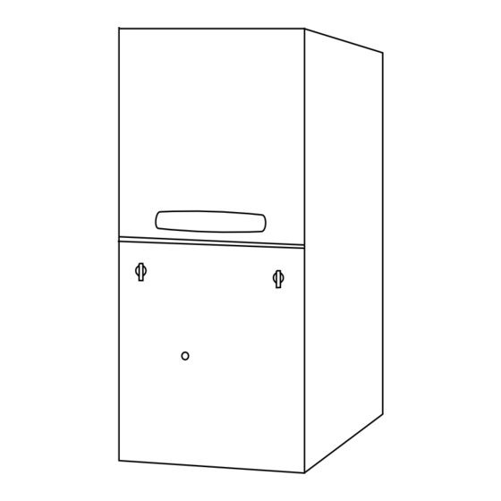
Page 4: Outline Drawing
Installer’s Guide 18-CD30D1-9... - Page 5 Installer’s Guide 18-CD30D1-9...
-
Page 6: Installation Instructions
Installer’s Guide 7. When a furnace is installed so that supply ducts 4. Are there at least 3 inches of clearance between carry air circulated by the furnace to areas outside the furnace combustion air openings in the front the space containing the furnace, the return air panel and any closed panel or door provided? shall also be handled by a duct(s) sealed to the fur- 5. -
Page 7: Upflow Installation
Installer’s Guide ▲ DOWNFLOW INSTALLATIONS WARNING REQUIRED FLOOR OPENING: (DOWNFLOW) SAFETY HAZARD SEE FIGURE 2 AND FIGURE 3, AND TABLE 1 DO NOT INSTALL THE FURNACE DIRECTLY ON CAR- PETING, TILE OR OTHER COMBUSTIBLE MATERIAL HORIZONTAL INSTALLATION OTHER THAN WOOD FLOORING. FOR VERTICAL IMPORTANT: DOWNFLOW APPLICATIONS, SUBBASE (BAYBASE205) The 2/4TXC cased coil must be placed downstream of the... -
Page 8: Air For Combustion And Ventilation
Installer’s Guide fireplaces must be considered to avoid unsatisfactory furnace operation. OUTSIDE AIR IS RECOMMENDED The use of indoor air for most applications is acceptable, unless there is the presence of corrosive chemicals or contamination. Certain types of installation will require the use of outside air for combustion. -
Page 9: Duct Connections
Installer’s Guide CONFINED SPACE Confined spaces are installations with less than 50 cu. ft. of space per 1000 BTU/hr input from all equipment installed. Air for combustion and ventilation require- ments can be supplied from inside the building as in Figure 8 or from the outdoors, as in Figure 9. - Page 10 Installer’s Guide With a parallel flow arrangement, the dampers or other PREPARATION FOR UPFLOW BOTTOM AND SIDE means used to control flow of air shall be adequate to RETURN AIR FILTER INSTALLATION prevent chilled air from entering the Furnace, and if All return air duct systems should provide for installa- manually operated, must be equipped with means to tion of return air filters.
-
Page 11: Return Air Filters
TABLE 4 MODELS CABINET FILTER NUMBERS WIDTH QTY & SIZE *UHMB060ACV3VA 17-1/2" 1 - 17" X 25" X 1" FILTER RACK ASSEMBLY *UHMB080ACV3VA *UHMC100ACV4VA 21" 1 - 20" X 25" X 1" *UHMD120ACV5VA 24-1/2"... - Page 12 Installer’s Guide ALTERNATE FILTER RACK INSTALLATION FOR BOT- BOTTOM ENGAGEMENT TOM RETURN - BAYRACK960 Filter Rack The following checklist should be used when installing a Retaining bottom return filter on an upflow furnace: Furnace Screw/Pin Filter Cabinet a. Remove the filter. Rack Side b.
- Page 13 LOCATIONS ALTERNATE BOTTOM Table 4A CONVERSION KITS FOR FILTER CLIPS LOCATIONS HORIZONTAL FILTERS CABINET CONVERSION MODEL NUMBERS WIDTH KIT NUMBER *UHMB060ACV3VA 17-1/2" BAYFLTR203 *UHMB080ACV3VA 21" BAYFLTR204 *UHMC100ACV4VA *UHMD120ACV5VA 24-1/2" BAYFLTR205 1. *First letter may be "A" or "T" 2. Kit includes Filters and Brackets necessary for Horizontal Filters.
- Page 14 Installer’s Guide INSTALLING THE FILTER Downflow furnace filters must be located outside the The filter may need to be cut to fit the unit depending furnace cabinet. Typical installations are shown in Fig- on the location of the return air filter. ure 22.
-
Page 15: General Venting Information
Installer’s Guide ▲ GENERAL VENTING INFORMATION WARNING THIS FURNACE MUST BE VENTED TO THE OUT- CARBON MONOXIDE POISONING HAZARD DOORS. THESE FURNACES ARE INDUCED DRAFT Failure to follow the steps outlined below for each VENTED AND MUST NOT BE CONNECTED TO ANY appliance connected to the venting system being VENT SERVING ANOTHER APPLIANCE. - Page 16 Installer’s Guide 2" TO 3" COUPLING For NONDIRECT VENT APPLICATION: The furnace shall be vented to the exterior of the house, #CPL00938 but combustion air may enter from the surrounding area as long as combustion air requirements are met. (See AIR FACTORY SUPPLIED ONLY FOR COMBUSTION AND VENTILATION) WITH THE FOLLOWING...
- Page 17 Installer’s Guide EX. 2 — NOTE: If only the flue gas pipe is to the outside of the struc- Example 2 shows the vent pipe exhausting through the ture, a straight section of pipe (long enough to exit the roof and the inlet air coming from the interior of the Furnace cabinet) must be attached to the inlet air side house (See Note).
-
Page 18: Venting Materials
Installer’s Guide TABLE 9 PVC VENT FITTING MATERIAL These fittings are available from your Gas Furnace Distributors for U.S. applications only. KIT02282 KIT02281 PLASTIC PIPE DESIGNATIONS ASTM STANDARD PIPE TYPE ALLOWABLE TEMPERATURE MARKING F891 CELLULAR CORE *158 ASTM F891 D2665 DWV PIPE **158 ASTM D2665... -
Page 19: Vent Length Table
Installer’s Guide TABLE 10 VENT LENGTH TABLE - MODULATING FURNACE MAXIMUM TOTAL EQUIVALENT LENGTH IN FEET FOR VENT AND INLET ALTITUDE AIR (SEE NOTES) 2 INCH PIPE 2.5 INCH PIPE 3 or 4 INCH PIPE 0-7000 Feet NATURAL GAS PROPANE NATURAL GAS PROPANE NATURAL GAS... -
Page 20: Venting Through The Roof
Installer’s Guide ▲ WARNING VENTING THROUGH THE ROOF CARBON MONOXIDE POISONING HAZARD DO NOT REPLACE ANY OF THE FACTORY SUPPLIED When penetrating roof with a 2" PVC Vent Pipe, a 2" VENTING COMPONENTS WITH FIELD FABRICATED electrical conduit flashing may be used for a weather PARTS. -
Page 21: Horizontal Venting Through The Wall
Installer’s Guide FLUE GAS DEGRADATION – The moisture content of HORIZONTAL VENTING THROUGH WALL the flue gas may have a detrimental effect on some IMPORTANT: building materials. This can be avoided by using the The building owner/maintenance provider must roof or chimney venting option. When wall venting is keep the area around the vent clear from snow. - Page 22 Installer’s Guide IMPORTANT: INSPECTION. The state or local gas inspector of the side wall horizontally vented gas fueled equipment shall not approve the installation unless, upon inspection, The Commonwealth of Massachusetts requires compliance the inspector observes carbon monoxide detectors and with regulation 248 CMR 4.00 and 5.00 for installation of signage installed in accordance with the provisions of 248 through –...
- Page 23 Installer’s Guide ANCHORS 12" MIN TO (4 req.) OVERHANG VENT PLATE VENT 1" + " 3.2" 12" MINIMUM TO OVERHANG COMBUSTION COMBUSTION SCREWS VENT (4 req.) VENT MAINTAIN 12 IN. MINIMUM CLEARANCE VENT ABOVE HIGHEST MAINTAIN 12" MINIMUM CLEARANCE ANTICIPATED SHOW ABOVE HIGHEST ANTICIPATED SNOW LEVEL LEVEL OR GRADE OR GRADE WHICHEVER IS GREATER...
- Page 24 Installer’s Guide Table 11 Non-Direct Vent Terminal Clearances Canadian Installations US Installations Clearance above grade, veranda, porch, deck, 12 inches (30 cm) 12 inches (30 cm) or balcony 6 inches (15 cm) for appliances =/< 10,000 Btuh (3 kw), 12 inches (30 cm) for appliances > 10,000 Btuh (3 kw) 4 feet (1.2m) below or to the side of opening;...
- Page 25 Installer’s Guide NOTE: VENT AND INLET MUST BE SUPPORTED AT A MAXIMUM OF 3' INTERVALS STRAPS OR OTHER SUITABLE SUPPORTS AT A MAXIMUM OF 3' 0" INTERVALS BAYAIR30AVENTA COMBUSTION STRAP (FIELD SUPPLIED) RAIN CAP VENT VENT 1" + 1/2" ELBOW COMBUSTION AIR (FIELD SUPPLIED)
- Page 26 Installer’s Guide SUPPORT HORIZONTAL PIPE EVERY 3' 0" WITH THE FIRST SUPPORT AS CLOSE TO THE FURNACE AS POSSIBLE. INDUCED DRAFT BLOWER, HOUSING, AND FURNACE MUST NOT SUPPORT THE WEIGHT OF THE FLUE PIPE. REMOVE RIBS FROM CAP VENT 12 INCHES MIN. CLEARANCE MUST BE MAINTAINED ABOVE HIGHEST ANTICIPATED SNOW LEVEL.
-
Page 27: Venting Routed Through A Masonry Chimney
Installer’s Guide PVC PLASTIC VENTING – ONLY TYPE 29-4C STAINLESS STEEL VENTING – THROUGH UNUSED CHIMNEY USED THROUGH CHIMNEY THAT VENTS ANOTHER GAS APPLIANCE STAINLESS STEEL VENT CAP STAINLESS STEEL VENT STAINLESS (OPTIONAL) CAP (OPTIONAL) STEEL STAINLESS STEEL VENT CAP VENT CAP SEE CAUTION 6 IN. -
Page 28: Electrical Connections
Installer’s Guide ELECTRICAL CONNECTIONS NOTE: The maximum total cable length for the entire Com- ▲ fort Control communicating system is 500 ft. 18 CAUTION AWG. The maximum distance of any single cable from a transformer is 250 ft. 18 AWG. Protect from Property Damage Do NOT connect the furnace line voltage to a GFCI pro- tected circuit. - Page 29 Installer’s Guide 41B - Communicating Indoor Unit with Communicating Comfort Control and 24VAC Single Stage Cooling 41C - 24 VAC Mode Indoor Unit with 24 VAC Comfort Control and 24VAC Single Stage Cooling 18-CD30D1-9 FIELD WIRING DIAGRAMS...
- Page 30 Installer’s Guide Field Wiring Diagrams continued 41D - 24 VAC Mode Indoor Unit with 24 VAC Comfort Control and 24VAC 2-Stage or 2-Step Cooling 41E - 24 VAC Mode Indoor Unit with 24 VAC Comfort Control and 24VAC Single Stage Heat Pump 18-CD30D1-9...
- Page 31 Installer’s Guide 41F - 24 VAC Mode Indoor Unit with 24 VAC Comfort Control and 24VAC 2-Stage or 2-Step Heat Pump 41G - Humidistat Hookup - 24 V Mode ONLY BK Jumper The factory installed jumper between "R" and "BK" on the circuit board must be cut if an optional humidistat is installed.
-
Page 32: Condensate Drain Instructions
Installer’s Guide CONDENSATE DRAIN INSTRUCTIONS VERTICAL APPLICATIONS ▲ CAUTION Upflow Vertical Furnace - The connection tubing for left and right side drainage is shipped in the blower It is recommended that an external overflow drain pan compartment. Install the connection tubing from the be installed under the furnace to prevent property dam- trap to the side of the unit and trim all excess tubing to age or personal injury from leaking condensate. - Page 33 Installer’s Guide Downflow Vertical Furnace - The furnace is shipped The furnace trap must be repositioned to the exterior of with the left side drainage setup. To change the right the cabinet. Remove the trap from its present location side drain, remove the drain lines from the trap, rotate and reposition the trap outside of the unit, through the the trap 180°...
-
Page 34: Gas Piping
Installer’s Guide GAS PIPING ▲ WARNING FIRE - EXPLOSION HAZARD DO NOT RUN FLEXIBLE GAS LINE THROUGH THE FURNACE CABINET WALL OR WITHIN THE FURNACE CABINET. FAILURE TO FOLLOW THIS WARNING COULD RESULT IN PROPERTY DAMAGE, SERIOUS PERSONAL INJURY, OR DEATH. ▲... - Page 35 Installer’s Guide AUTOMATIC GAS VALVE AUTOMATIC GAS VALVE IMPORTANT: WITH MANUAL SHUT-OFF WITH MANUAL SHUT-OFF sediment trap must be installed in the gas line before furnace valve. The sedi- ment trap must be located as close to DRIP DRIP the furnace cabinet as practical.
-
Page 36: Combustion And Input Check
Installer’s Guide COMBUSTION AND INPUT CHECK HIGH ALTITUDE DERATE (SEE ALSO HIGH ALTITUDE DERATE) ▲ CAUTION NOTE: Before checking or adjusting the gas pres- CAUTION sure, make sure the condensate trap has been Maintain manifold pressure as specified in Table 15 primed. - Page 37 Installer’s Guide If the desired input rate cannot be achieved with a TABLE 18 change in manifold pressure, then the orifices must be GAS FLOW IN CUBIC FEET PER HOUR changed. See Table 16 for replacement orifice part 2 CUBIC FOOT DIAL numbers.
- Page 38 Installer’s Guide To Pressure Switch PS-1 ! Important ! Brass orifices located in these two legs. H-Fitting must be installed in this orientation. VACUUM HOSE Burner Box ROUTING Pressure Switch PS-1 Orifice in H fitting must be pointing away from PS1 H-Fitting Pressure Switch PS-3...
-
Page 39: Start-Up And Adjustment
Installer’s Guide REINSTALLATION OF THE BURNER BOX COVER ing, check all gas connections for leaks with a soapy so- Figure 55 shows the correct way to reinstall the Burner lution — DO NOT CHECK WITH AN OPEN Box cover if adjustment or replacement of the Flame FLAME. -
Page 40: User Interface Menu
Installer’s Guide 1. Remove Blower Door panel by turning the two door USER INTERFACE MENU latches. 2. Lower door panel and remove from service access SERVICE PROCEDURE TO ACCESS area. USER INTERFACE FOR THE MODULATING FURNACE 3. Use one hand depress the door switch (there must This procedure should only be performed by trained be power to the control system for the display service personnel. - Page 41 Installer’s Guide TABLE 20 - USER INTERFACE MENU Power Up == WAIT == A/TCONT900 Variable Speed Standy Screen System Status Setup Options [ ] = Current Setting MODEL NUMBER CMFRT CNT MODE SERIAL NUMBER COMM [COMM] 24VAC * Unit specific COOLING CFM 2 COOLING CFM A/TUHMB060...
- Page 42 Installer’s Guide TABLE 20 - USER INTERFACE MENU - 24VOLT MENU (CONTINUED) 24V Variable Speed System Status Setup Options [ ] = Current Setting CMFRT CNT MODE COMM [24VAC] 24VAC * Unit specific A/TUHMB060 3T [3T] 1.5T 2T 2.5T COOLING CFM 2 COOLING CFM A/TUHMB080 3T [3T] 3.5T 2T 2.5T...
-
Page 43: Sequence Of Operation
Installer’s Guide SEQUENCE OF OPERATION 14. With a heat demand less than 65% from the communicating comfort control, the IFC signals SEQUENCE OF OPERATION – COMMUNICATING the variable speed inducer motor drive board to MODE ramp down to that corresponding demand speed. 1. - Page 44 Installer’s Guide SEQUENCE OF OPERATION – 24VAC Mode reduced in steps, decreasing the chance of burner 1. This furnace modulates between 40% and 100% of flame out. The W1 heating capacity is 40%. The capacity, in 3% increments, every 1 minute. The IFC will also decrease the indoor blower motor furnace always lights at approximately 65% and speed.
- Page 45 Installer’s Guide 17. PS1 and PS2 close. 18. The IFC receives a 24 VAC signal from PS1 and PS2 when they close. This verifies the vent motor is moving the correct amount of combustion air through the furnace and the vent system.
-
Page 46: Unit Test Mode
Installer’s Guide UNIT TEST MODE B) GAS VALVE SETUP (MANIFOLD PRESSURE AD- JUSTMENT) A) SIMPLE NOTE: To obtain an accurate manifold pressure Note: measurement ,the manifold pressure must be refer- Stage 1 = 40% (low) heat, Stage 2 = 100% (high) heat enced to the burner box, since the burner box pres- A qualified technician can cycle the Variable sure tap equalizes the gas valve pressure regulator. - Page 47 Installer’s Guide CORRECT METHOD OF CHECKING DIRECT VENT MANIFOLD PRESSURE WITH BURNER BOX REFERENCED ▲ WARNING EXPLOSION HAZARD REPLACE AND/OR TIGHTEN ALL PLUGS REMOVED OR LOOSENED WHEN ADJUSTING GAS PRESSURE. LEAK CHECK THE FITTINGS BEFORE PLACING INTO Slope REGULAR SERVICE. FAILURE Gauge TO FOLLOW THIS WARNING COULD RESULT IN SERIOUS...
- Page 48 Installer’s Guide 100% (HIGH) HEAT ADJUSTMENT: h. Allow 5 minutes to pass before attempting to adjust the 40% manifold pressure. This will insure that COUNTERCLOCKWISE TO DECREASE MANI- FOLD PRESSURE OR CLOCKWISE TO IN- the learning routine is complete and that the heat CREASE MANIFOLD PRESSURE.
- Page 49 Installer’s Guide TABLE 22 STAND ALONE OPERATION (CONTINGENCY MODE) The Contingency Mode allows the installer to set the FINAL NG MANIFOLD PRESSURE SETTINGS (inches w.c.) Furnace Input rate equipment to operate in an ON/ OFF Duty Cycle (KBTU/hr) 100% mode. This mode will be activated using the User 0.7 + 0.2 / - 0.0 Not Adjustable 3.5 ±...
- Page 50 Installer’s Guide • IFC INDUCER LEARNING ROUTINE SEQUENCE Start and NO [NO] will now be displayed. With a NO/NO question being asked, use the 3or4 • The furnace IFC will go through an inducer learning arrows to select the YES and then press the routine for three pressure switches.
- Page 51 Installer’s Guide PS-3 INDUCER LEARNING ROUTINE NOTE: The furnace lights at approximately 65% of capacity. • When the furnace IFC receives a digital signal for • When the burner flame is detected by the furnace 100% (high) heat from the comfort control it will IFC, a forty-five second time delay for indoor blower begin the PS-3 inducer learning routine.
-
Page 52: Control And Safety Switch Adjustments
Installer’s Guide ▲ CONTROL AND SAFETY SWITCH WARNING ADJUSTMENTS ELECTRICAL SHOCK HAZARD LIMIT SWITCH CHECK OUT DISCONNECT POWER TO THE UNIT BEFORE REMOV- The Limit Switch is a safety device designed to close ING THE BLOWER DOOR. ALLOW A MINIMUM OF 10 the Gas Valve should the Furnace become overheated. -
Page 53: Conditions Effecting Furnace Operation
IFC ERROR FLASH CODES Installer’s Guide CONDITIONS AFFECTING FURNACE 3. POWER FAILURE If there is a power failure during a Heating Cycle, the OPERATION system will restart the Ignition Sequence automatically when power is restored, if the Comfort Control still NOTE: calls for heat. -
Page 54: Alert Code Recovery
Installer’s Guide Table 23 ALERT CODE RECOVERY On power up, last 4 Alerts, if any, will be flashed on the DESCRIPTION FUNCTION Red Alert LED. The newest Alert detected will flash GREEN STATUS LED FAST FLASH - CALL FOR HEAT first and the oldest last. -
Page 55: Furnace Alert Codes
Installer’s Guide TABLE 24- FURNACE 9 08 00 009 6 ALERT CODES Alert Notification Alert Alert Group Alert Description Code Fault LED COM LED User Interface Display Control Display Flame is off when flame should be RECYCLE detected. Furnace tries to relight Flame lost or Ignition itself. - Page 56 Literature Order Number 18-CD30D1-9 File Number 18-CD30D1-9 Trane 6200 Troup Highway Supersedes 18-CD30D1-8 Tyler, TX 75707 Date 06/11 Since the manufacturer has a policy of continuous product and product data improvement, it reserves the For more information contact right to change design and specifications without notice.