Table of Contents
Advertisement
Quick Links
Advertisement
Table of Contents

Related Manuals for Omega HHM17


Summary of Contents for Omega HHM17
- Page 1 OMEGA...
- Page 2 European New Approach Directives. OMEGA will add the CE mark to every appropriate device upon certification. The information contained in this document is believed to be correct but OMEGA Engineering, Inc. accepts no liability for any errors it contains, and reserves the right to alter specifications without notice.
-
Page 3: Safety Information
SAFETY INFORMATION The following safety information must be observed to insure maximum personal safety during the operation at this meter: 1. Do not use the meter if the meter or test leads look damaged, or if you suspect that the meter is not operating properly. 2. -
Page 4: Specifications
SPECIFICATIONS Display: 3¾ digit (4000 counts), 9999counts (Frequency mode), 40 segments analog bar graph and function units sign annunciators. Polarity: Automatic, positive implied, negative polarity indication. Overrange: "4000"or"-4000" Most Significant Digit blinks. Low battery indication: the " " is displayed when the battery voltage drops below the operating level. - Page 5 DC VOLTS Ranges: 400mV,4V,40V,400V,600V Resolution: 100µV Accuracy: ±(0.25%rdg + 1dgt) on 400mV to 400V ranges ±(0.25%rdg + 3dgts) on 600V range Input impedance: >10MW Overload protection: 600VDC or AC rms AC VOLTS Ranges: 400mV,4V,40V,400V,600V (400mV only Manual @50Hz-100Hz) Resolution: 100µV Accuracy: Range 100Hz...
- Page 6 DC CURRENT Ranges: 4mA,40mA,400mA,10A Accuracy: ±(0.5%rdg + 1dgt) on mA ranges ±(2.0%rdg + 1dgt) on 10A range Input protection: 0.5A / 250V fast blow ceramic fuse 10A / 600V fast blow ceramic fuse AC CURRENT (50Hz - 500Hz) Ranges: 4mA,40mA,400mA,10A Accuracy: ±(1.0%rdg + 4dgts) on mA ranges ±(3.0%rdg + 4dgts) on 10A range Input protection: 0.5A / 250V fast blow ceramic fuse...
- Page 7 DIODE TEST Test current: 1.0mA±0.6mA Accuracy: ±(3.0%rdg + 3dgts) Open circuit volts: 3.0Vdc typical Overload protection: 500VDC or AC rms CAPACITANCE Ranges: 4nF,40nF,400nF,4µF,40µF Accuracy: ±(2.0%rdg+20dgts) on 4n Frange(use 0ADJ) ±(2.0%rdg + 4dgts) on 40nF to 40µF ranges ±(5.0%rdg + 4dgts) above 40µF Overload protection: 500VDC or AC rms FREQUENCY (Autoranging) Ranges: 100Hz,1KHz,10KHz,100KHz,700KHz...
-
Page 8: Operation
OPERATION Before taking any measurements, read the Safety Information Section. Always examine the instrument for damage, contamination (excessive dirt, grease, etc.) and defects. Examine the test leads for cracked or frayed insulation. If any abnormal conditions exist do not attempt to make any measurements. - Page 9 RELD D D D D Button Press (REL) button to enter the Relative mode, the "RELD" annunciator turn on, zero the display, and store the displayed reading as a reference value. Press and hold down the (REL) button for 2 seconds to exit the relative mode. MIN / MAX button Press (MIN / MAX) button to enter the MIN MAX Recording mode.
- Page 10 HOLD Button Press (HOLD) button to toggle in and out of the Data Hold mode, except if you are already in the MIN MAX Recording mode. In the Data Hold mode, the "HOLD" annunciator is displayed and the last reading is held on the display, the beeper emits a tone, and the automatic power-off feature is disable.
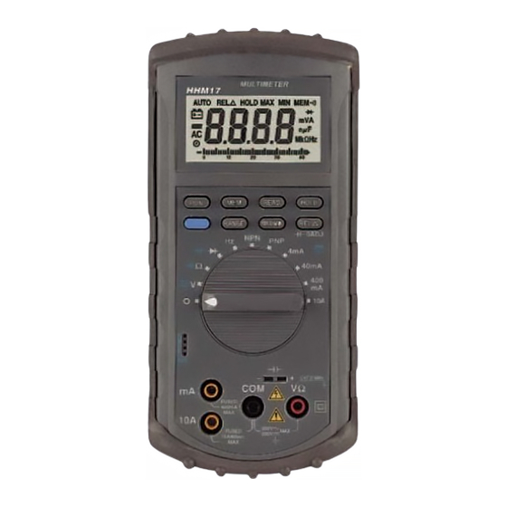
- Page 11 Alternate Function Button The Alternate Function button is Blue in color. Press it to toggle to the alternate function (AC, Audible continuity and Capacitance) shown in Blue on the meter face. Voltage Measurements 1. Connect the red test lead to the "VW " jack and the black test lead to the "COM"...
- Page 12 Resistance and Continuity Measurements 1. Set the Function/Range switch to the desired resistance range or continuity position. 2. Remove power from the equipment under test. 3. Connect the red test lead to the "VW " jack and the black test lead to the "COM"...
- Page 13 7. If the junction is measured in a circuit and a low reading is obtained with both lead connections, the junction may be shunted by a resistance of less than 1kW . In this case the diode must be disconnected from the circuit for accurate testing.
-
Page 14: Maintenance
MAINTENANCE WARNING Remove test leads before changing battery or fuse or performing any servicing. Battery Replacement Power is supplied by a 9 volt "transistor" battery. (NEDA 1604, IEC 6F22). The " " appears on the LCD display when replacement is needed. To replace the battery, remove the two screws from the back of the meter and lift off the battery case. - Page 15 CONDITIONS: Equipment sold by OMEGA is not intended to be used, nor shall it be used: (1) as a "Basic Component" under 10 CFR 21 (NRC), used in or with any nuclear installation or activity; or (2) in medical applications or used on humans. Should any...
-
Page 16: Data Acquisition
Where Do I Find Everything I Need for Process Measurement and Control? OMEGA...Of Course! TEMPERATURE DATA ACQUISITION PRESSURE/STRAIN AND FORCE HEATERS FLOW/LEVEL ENVIRONMENTAL MONITORING AND CONTROL pH/CONDUCTIVITY M-2855/0799...