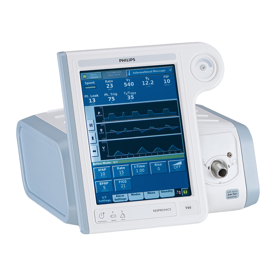
Philips Respironics V60 Service Manual
Respironics v60 ventilator
Hide thumbs
Also See for Respironics V60:
- User manual (212 pages) ,
- User manual (194 pages) ,
- Developer's manual (284 pages)
Table of Contents
Advertisement
Advertisement
Table of Contents
Troubleshooting

Related Manuals for Philips Respironics V60


Summary of Contents for Philips Respironics V60
- Page 1 Respironics V60 Ventilator Service Manual...
- Page 2 For Technical Support and Customer Service, contact: USA and Canada: 1-800-345-6443 (toll free) or 724-387-4000 Respironics Europe, Africa, Middle East: +33-1-47-52-30-00 Respironics Asia Pacific: +852-3194-2280 Facsimile: 724-387-5012 United States of America Respironics California, Inc. 2271 Cosmos Court Carlsbad, CA 92011 Email and Web Addresses service@respironics.com clinical@respironics.com...
-
Page 3: Table Of Contents
3.2.7 Flow Sensors ......... . 3-10 1049766 Rev A V60 Ventilator Service Manual... - Page 4 6.5.1 Programming the Ventilator Serial Number ..... 6-21 6.5.2 Programming Ventilator Power-On Hours..... . . 6-23 V60 Ventilator Service Manual 1049766 Rev A...
- Page 5 7.38 Labels ..........7-42 1049766 Rev A V60 Ventilator Service Manual...
- Page 6 8.9 Performance Verification Data Form ......8-45 V60 Ventilator Service Manual 1049766 Rev A...
- Page 7 Index..........Index-1 1049766 Rev A V60 Ventilator Service Manual...
- Page 8 Table of Contents (This page is intentionally blank.) viii V60 Ventilator Service Manual 1049766 Rev A...
-
Page 9: Introduction And Intended Use
V60. Review the operating instructions for the V60 ventilator before running tests, checking operational readiness, or initiating patient use. These instructions include important information about ventilator safety and operation. -
Page 10: Intended Use
Chapter 1 Introduction and Intended Use 1.1 Intended Use The Respironics V60 ventilator is an assist ventilator that is intended to augment patient breathing. It is intended for spontaneously breathing individuals who require mechanical ventilation: patients with respiratory failure, chronic respiratory insufficiency, or obstructive sleep apnea in a hospital or other institutional settings under the direction of a physician. -
Page 11: Recommended Test Equipment, Tools, And Supplies
Introduction and Intended Use 1.2 Recommended Table 1-1 lists the recommended tools, test equipment, and materials required Test Equipment, to service and maintain the V60 ventilator. Tools, and Supplies Table 1-1: Recommended Test Equipment, Tools, and Materials Description Manufacturer and Model... - Page 12 1 to 25 in.-lbf Torque driver capable of 226 to 1130 N cm/ Local supplier 20 to 100 in.-lbf Vacuum, ESD-safe 3M Model 497-AJM or equivalent Workstation, antistatic 3M Model 725 or equivalent V60 Ventilator Service Manual 1049766 Rev A...
-
Page 13: Where To Go For Help
Introduction and Intended Use 1.3 Where to Go for For Technical Support and Customer Service, contact: Help USA and Canada: 800-345-6443 or 724-387-4000 Respironics Europe, Africa, Middle East: +33-1-47-52-30-00 Respironics Asia Pacific: +852-3194-2280 Facsimile: +1-724-387-5012 1049766 Rev A V60 Ventilator Service Manual... - Page 14 Chapter 1 Introduction and Intended Use (This page is intentionally blank.) V60 Ventilator Service Manual 1049766 Rev A...
-
Page 15: Warnings And Cautions
It is not intended to provide the total ventilatory requirements of the patient. WARNING: We do not recommend you use the Respironics V60 ventilator on patients who require ventilation at predetermined tidal volumes. The ventilator provides continuous positive airway pressure (CPAP) and positive pressure ventilation (S/T, PCV, and AVAPS) and is indicated for assisted ventilation only. - Page 16 Follow all instructions for proper use of the battery. • Do not short-circuit the battery or allow metallic or conductive objects to contact the battery connector housing. • Use the battery with the Respironics V60 ventilator only. V60 Ventilator Service Manual 1049766 Rev A...
- Page 17 NOTE: The Respironics V60 ventilator parts that have patient contact are free of latex. NOTE: If an alarm persists for no apparent reason, discontinue ventilator use and contact Respironics.
-
Page 18: Preparing For Ventilation
Do not use antistatic or electrically conductive tubing. WARNING: To prevent patient or ventilator contamination, recommend you use a Respironics-approved main flow bacteria filter on the patient gas outlet port. Filters not approved by Respironics may degrade system performance. V60 Ventilator Service Manual 1049766 Rev A... - Page 19 CAUTION: For 120 V equipment, grounding reliability can only be achieved when it is connected to an equivalent receptacle marked “hospital only” or “hospital grade.” 1049766 Rev A V60 Ventilator Service Manual...
-
Page 20: Operation
CAUTION: To prevent possible damage to the ventilator, always ship it with the original packing material. If the original material is not available, contact Respironics to order replacements. V60 Ventilator Service Manual 1049766 Rev A... -
Page 21: First-Time Installation
> 1 mA. 2.8 Diagnostic Mode WARNING: To prevent possible patient injury, do not enter the diagnostic mode while a patient is connected to the ventilator. Verify that the patient is disconnected before proceeding. 1049766 Rev A V60 Ventilator Service Manual... - Page 22 Chapter 2 Warnings and Cautions (This page is intentionally blank.) V60 Ventilator Service Manual 1049766 Rev A...
-
Page 23: Theory Of Operation
Chapter 3. Theory of Operation The V60 ventilator is a microprocessor-controlled gas flow control and monitoring system that can deliver air and oxygen to augment or replace the work normally performed by the patient’s respiratory system. The ventilator uses electromechanical control circuits, flow and pressure monitors, and software programs to deliver pressure controlled breaths. -
Page 24: Air Inlet
The internal exhalation port continually clears gas from the ventilator airway to ensure delivery of an accurate oxygen mixture. Figure 3-1 shows a pneumatic schematic of the V60 ventilator. Proximal pressure sensor... -
Page 25: Air Flow Sensor
Machine pressure transducer transducer DA PCBA a range of 0 to 87 psig. An alarm results if oxygen supply pressure is below 40 psig (276 kPa) or above 92 psig (634 kPa). 1049766 Rev A V60 Ventilator Service Manual... -
Page 26: Manifold, Oxygen Inlet Filter, Filter Element
(RPM) in 120 msec from a nominal 5- to 25-cmH Blower pressure rise. Maximum motor speed is approximately 40,000 RPM. The blower motor has internal Hall Effect sensors that are monitored by the MC PCBA and measure impeller speed. V60 Ventilator Service Manual 1049766 Rev A... -
Page 27: Solenoid Valves
SOL3, SOL4: Proximal pressure autozero solenoids. SOL4: Also connects machine pressure to the proximal pressure transducer during autozero. SOL2, SOL4: Machine pressure autozero solenoids. SOL1: Purge solenoid, uses the machine pressure line to purge the proximal pressure line. 1049766 Rev A V60 Ventilator Service Manual... -
Page 28: Electronics
Flow sensors • User interface • Liquid crystal display (LCD) • Backlight inverter PCBA • Touch screen assembly • Nav-ring assembly • Power switch overlay • Switch PCB • User interface (UI) PCBA V60 Ventilator Service Manual 1049766 Rev A... -
Page 29: Power Management (Pm) Pcba
Provides operating power when AC power is not available. • Provides charge and temperature status to the PM PCBA. Internal battery • Internal circuitry monitors battery status, provides self-contained fault control features, and communicates this information to the PM PCBA. 1049766 Rev A V60 Ventilator Service Manual... -
Page 30: Cpu Pcba
Electrical interfaces to the power management (PM) and motor controller (MC) PCBAs. • Two USB ports and an ethernet connection are designed for future enhancements. Table 3-1 summarizes hospital information system (HIS) RS-232 port pinout. V60 Ventilator Service Manual 1049766 Rev A... - Page 31 Chapter 3: Theory of Operation Table 3-1: V60 HIS Serial Communications Port Pinout Signal Description HIS_RS232_SHLD Power HIS RS232 cable shield HIS_RS232_TxD Output HIS RS232 transmit data output HIS_RS232_RxD Input HIS RS232 receive data input HIS_RS232_RTS Output HIS RS232 ready to send...
-
Page 32: Motor Controller (Mc) Pcba
Air flow sensor measures flows from -240 to 240 SLPM. Oxygen flow sensor measures flows from 0 to 240 SLPM. • Includes EEPROM for calibration data, board identification information, and power-on hours for each flow sensor. Air flow sensor 3-10 V60 Ventilator Service Manual 1049766 Rev A... -
Page 33: User Interface
3.2.10 Backlight Inverter PCBA • Backlight inverter PCBA provides adjustable backlight drive voltage. • Backlight dimming capability using a 0 to 3.5-V control voltage from the CPU PCBA through the PM PCBA Backlight inverter PCBA 3-11 1049766 Rev A V60 Ventilator Service Manual... -
Page 34: Touch Screen Assembly
Power switch overlay 3.2.14 Switch PCBA • Interconnection between rotary adjustment and UI PCBA and CPU PCBA. • Provides a center push button and interface to nav-ring. • Connects to UI PCBA. Switch PCBA 3-12 V60 Ventilator Service Manual 1049766 Rev A... -
Page 35: Ui Pcba
Provides a connection for backlight PCBA, touch panel, switches, and switch PCBA to PM PCBA. • Mounts behind LCD, provides connectors to backlight inverter PCBA, power switch overlay, switch PCBA, and touch screen. • Connects to PM PCBA. UI PCBA 3-13 1049766 Rev A V60 Ventilator Service Manual... -
Page 36: Electronic Signal Paths
Chapter 3: Theory of Operation 3.3 Electronic Signal The following table summarizes the electronic signal paths for V60 ventilator components. Paths Table 3-2: V60 Signal Paths Component Signal Path Sequence Air flow sensor DA PCBA, MC PCBA, CPU PCBA Alarm indicator... - Page 37 Chapter 3 Theory of Operation Figure 3-2 shows a wiring diagram for the main assembly. Figure 3-2: V60 Main Assembly Wiring Diagram. 3-15 1049766 Rev A V60 Ventilator Service Manual...
- Page 38 Chapter 3 Theory of Operation (This page is intentionally blank.) 3-16 V60 Ventilator Service Manual 1049766 Rev A...
- Page 39 Chapter 3 Theory of Operation Figure 3-3 shows a wiring diagram for the UI subsystem. Figure 3-3: V60 UI Assembly Wiring Diagram 3-17 1049766 Rev A V60 Ventilator Service Manual...
- Page 40 Chapter 3 Theory of Operation (This page is intentionally blank.) 3-18 V60 Ventilator Service Manual 1049766 Rev A...
- Page 41 Chapter 3 Theory of Operation Figure 3-4 shows a block diagram of the power supply. Figure 3-4: Power Supply Block Diagram 3-19 1049766 Rev A V60 Ventilator Service Manual...
- Page 42 Chapter 3 Theory of Operation (This page is intentionally blank.) 3-20 V60 Ventilator Service Manual 1049766 Rev A...
- Page 43 Chapter 3 Theory of Operation Figure 3-5 shows a block diagram of the PM PCBA. Figure 3-5: Power Management (PM) PCBA Block Diagram 3-21 1049766 Rev A V60 Ventilator Service Manual...
- Page 44 Chapter 3 Theory of Operation (This page is intentionally blank.) 3-22 V60 Ventilator Service Manual 1049766 Rev A...
- Page 45 Chapter 3 Theory of Operation Figure 3-6 shows a block diagram of the MC PCBA. Figure 3-6: Motor Controller (MC) PCBA Block Diagram 3-23 1049766 Rev A V60 Ventilator Service Manual...
- Page 46 Chapter 3 Theory of Operation (This page is intentionally blank.) 3-24 V60 Ventilator Service Manual 1049766 Rev A...
-
Page 47: Periodic Maintenance
(Table 4-1) to ensure consistent ventilator operation. Hospital personnel can perform all maintenance tasks except the annual preventive maintenance procedures (the preventive maintenance procedures must be performed by a qualified service technician). The V60 Ventilator User Manual summarizes periodic care and maintenance procedures. Table 4-1: Periodic Maintenance Procedures... -
Page 48: Annual Preventive Maintenance Instructions
Use a clean patient circuit and filters when performing any testing or operational checkout. 1. Clean the exterior of the V60 ventilator using universal precautions (including mask, gloves, eye protection). 2. Enter Diagnostic mode by pressing and holding the nav-ring Enter button and turn on the ventilator by pressing the On/Shutdown button on the user interface. - Page 49 Chapter 4 Periodic Maintenance 3. Touch Service to display the V60 Ventilator Information screen (Figure 4-2). Figure 4-2: Ventilator Information Screen 4. Record the following information on the Performance Verification Data Form (Chapter 8): • Software options • Ventilator serial number •...
- Page 50 Cooling fan filter Figure 4-3: Cooling Fan Filter Retainer 13. Reassemble the V60 ventilator and complete the Performance Verification (Chapter 8). 14. If the ventilator is not already in diagnostic mode, press and hold the nav-ring Enter button and turn on the ventilator by pressing the On/ Shutdown button on the user interface.
- Page 51 (all caps) in the dialog box, and press Enter to reset hours since last PM to zero (Figure 4-4). Figure 4-4: Reset Hours since Last PM Command (HyperTerminal) 18. When the hours since last PM have been successfully reset, the dialog box displays: ?RESETPMOK 1049766 Rev A V60 Ventilator Service Manual...
- Page 52 21. Touch System Settings, and then touch Restore Default Settings. 22. Touch Date/Time and correct the date and time if necessary. 23. Turn the V60 ventilator off by pressing the ON/Shutdown button. 24. Upon successful completion of the performance verification, hours reset, and restoring the default settings, enter the required information on the PM and electrical safety labels.
- Page 53 Chapter 4 Periodic Maintenance Affix the labels to the V60 ventilator (Figure 4-6). PM label Electrical safety label Figure 4-6: Electrical Safety and PM Label Placement 25. Apply the clear chemical-resistant label over the PM label. 26. The annual PM is complete.
- Page 54 Chapter 4 Periodic Maintenance (This page is intentionally blank.) V60 Ventilator Service Manual 1049766 Rev A...
-
Page 55: Diagnostic Mode And Troubleshooting
2. Within five seconds, press the nav-ring Enter button again to enter the Diagnostics Menu (Figure 5-1). Diagnostics Menu Figure 5-1: 3. To exit diagnostic mode at any time, press the ON/Shutdown button. 1049766 Rev A V60 Ventilator Service Manual... -
Page 56: System Settings
The System Settings button allows access to these functions (Figure 5-2): • Language (language button is a different color) • Date/Time • Pressure Units • Restore Default Settings • Software Options • Baud Rate Figure 5-2: Diagnostic Mode: System Settings V60 Ventilator Service Manual 1049766 Rev A... -
Page 57: Selecting A Language
2. Touch the language button on the Set Language screen (Figure 5-3). Figure 5-3: Set Language Screen 3. The screen shows the selected language (Figure 5-4). 4. To apply the new language, touch Ventilator Shutdown. To exit without changing the language, touch Cancel. 1049766 Rev A V60 Ventilator Service Manual... - Page 58 Chapter 5 Diagnostic Mode and Troubleshooting Figure 5-4: Set Language - Apply or Cancel V60 Ventilator Service Manual 1049766 Rev A...
-
Page 59: Setting Date And Time
1. From the System Settings screen, touch Date/Time. 2. Enter the date and time, then touch Accept (Figure 5-5). To exit without changing the date and time, touch Cancel. Figure 5-5: Set Date and Time Screen 1049766 Rev A V60 Ventilator Service Manual... -
Page 60: Restoring Default Settings
Figure 5-6: Restore Default Settings Screen 3. When all ventilator and alarm settings have been restored to factory default values, the screen displays this message: Ventilation and Alarm Settings have been restored to factory defaults. V60 Ventilator Service Manual 1049766 Rev A... -
Page 61: Selecting Pressure Units
3. The screen displays the selected pressure unit and this message: Pressure units will apply after a ventilator shutdown and restart. 4. To apply the new unit of pressure, touch Ventilator Shutdown. To exit without changing the unit of pressure, touch Cancel. 1049766 Rev A V60 Ventilator Service Manual... -
Page 62: Enabling Software Options
4. When the software option has been successfully enabled, the screen displays Enabled: followed by the option name. 5. Repeat as needed to enable additional options. 6. To exit the Enable Software Options screen at any time, touch Back to System Settings. V60 Ventilator Service Manual 1049766 Rev A... -
Page 63: Baud Rate
2. Touch the button to select the Baud rate (Figure 5-9). Figure 5-9: Set Baud Rate Screen 3. The screen then displays this message: Baud rate is now set to: followed by the selected Baud rate. 1049766 Rev A V60 Ventilator Service Manual... -
Page 64: Service
Output controls • Miscellaneous (significant event log, download mode, and touch screen diagnostics, high pressure leak test, and system leak test). NOTE: Service button functions are intended for use by qualified service technicians. 5-10 V60 Ventilator Service Manual 1049766 Rev A... -
Page 65: Viewing Ventilator Information
2. The Ventilator Information screen displays software options, serial numbers, software versions, power-on hours, hours since last PM, and information on the internal battery and PCBAs (Figure 5-10). Figure 5-10: Ventilator Information Screen 5-11 1049766 Rev A V60 Ventilator Service Manual... -
Page 66: Pneumatic Controls
1. From the Service screen, touch the Pneumatics tab. 2. The screen displays real-time diagnostic information and pneumatic controls (Figure 5-11). Figure 5-11: Pneumatic Controls Screen 5-12 V60 Ventilator Service Manual 1049766 Rev A... -
Page 67: Output Controls
+ 23 counts of the set value. 1. From the Service screen, touch the Outputs tab. 2. The screen shows diagnostic information and output controls (Figure 5-12). Figure 5-12: Output Controls Screen 5-13 1049766 Rev A V60 Ventilator Service Manual... -
Page 68: Miscellaneous
2. The screen includes the Significant Event Log, Download Mode, Touch Screen Diagnostics, High Pressure Leak Test, and System Leak Test buttons (Figure 5-13). Figure 5-13: Miscellaneous Screen 3. To exit the Miscellaneous screen at any time, touch Back to Diagnostics Menu. 5-14 V60 Ventilator Service Manual 1049766 Rev A... - Page 69 3. To display the beginning or end of the significant event log, touch the To Newest or To Oldest button. Refer to Chapter 6, Reports and Software Downloads for information on interpreting the significant event log and saving it to a computer. 5-15 1049766 Rev A V60 Ventilator Service Manual...
- Page 70 Refer to Chapter 6, Reports and Software Downloads for more information on downloading software. 2. When the software download is complete, the download complete screen appears (Figure 5-15). Figure 5-15: Download Complete Screen 5-16 V60 Ventilator Service Manual 1049766 Rev A...
- Page 71 1. From the Miscellaneous screen, touch Touch Screen Diagnostics. 2. At the touch screen diagnostics screen (Figure 5-15), touch the screen in multiple places to verify correct touch screen function. Figure 5-16: Touch Screen Diagnostics Screen 5-17 1049766 Rev A V60 Ventilator Service Manual...
-
Page 72: Touch Screen Calibration
If the Touch Screen Calibration button does not respond, press the nav- ring Enter button to begin. 2. Follow the onscreen instructions to perform the calibration. Touch the middle of each target with a blunt, narrow object. Figure 5-17: Calibrate Touch Screen 5-18 V60 Ventilator Service Manual 1049766 Rev A... -
Page 73: Diagnostic Codes, Alarms, And Troubleshooting
2.Replace MC PCBA. 1006 DA PCBA ADC failed. 1.Replace DA PCBA. (CBIT) 1007 Machine and proximal pressure sensors failed. 1.Replace DA PCBA to MC PCBA (POST) cable. 2.Replace DA PCBA. 1008 (CBIT) 5-19 1049766 Rev A V60 Ventilator Service Manual... - Page 74 2.Replace UI to PM PCBA cable. 3.Replace PM PCBA (PM PCBA only if LED is functioning). 1106 Machine pressure sensor calibration data error. 1.Replace DA PCBA. (POST) Proximal pressure is not measured. Pressure-related alarms are compromised. 5-20 V60 Ventilator Service Manual 1049766 Rev A...
- Page 75 1.Replace flow sensor cable. (POST) 2.Replace flow sensor assembly. Ventilation continues with air only. 3.Replace DA PCBA. 1.Replace DA PCBA. 1110 Oxygen pressure sensor calibration data error. (POST) Ventilation continues with air only. 5-21 1049766 Rev A V60 Ventilator Service Manual...
- Page 76 5 V supply failed. (POST) 1119 12 V supply failed. 1.Replace PM PCBA. (CBIT) 1.Replace power supply. 111A 24 V supply failed. (POST) 111B 35 V supply failed. 1.Replace PM PCBA. (POST) 2.Replace MC PCBA. 5-22 V60 Ventilator Service Manual 1049766 Rev A...
- Page 77 1.Verify that cooling fan RPM is (CBIT) 4000 + 1000 RPM. Ventilator overheating possible. 2.Replace fan. 3.Replace PM PCBA. 1.Repeat software download. 1126 Flash file system error. 2.Replace CPU PCBA. 1127 OVP circuit failed. 1.Replace MC PCBA. 5-23 1049766 Rev A V60 Ventilator Service Manual...
- Page 78 Pressures exceed ventilator-defined thresholds. Ventilation appropriate. If problem persists, continues. Autoresets when alarm condition removed. provide alternative ventilation. Transitions to the ventilator inoperative state if pressure Service ventilator. continues to rise. 5-24 V60 Ventilator Service Manual 1049766 Rev A...
- Page 79 • The Lo Rate setting is < 4 BPM and there are no breaths for > 60/Lo Rate setting. • The Lo Rate setting is > 4 BPM and there are no breaths for > 15 sec. 5-25 1049766 Rev A V60 Ventilator Service Manual...
- Page 80 Check patient. Confirm that Too High pressure settings are compatible with target. Evaluate pressure and AVAPS target pressure is less than Min P setting. The volume settings. ventilator limits applied pressure to Min P. 5-26 V60 Ventilator Service Manual 1049766 Rev A...
- Page 81 If not, replace the oxygen solenoid valve. 4.Verify that the oxygen pressure transducer is reading correctly. If not, replace the DA PCBA. 5-27 1049766 Rev A V60 Ventilator Service Manual...
- Page 82 If not, replace the oxygen solenoid valve. 4.Verify that the oxygen pressure transducer is reading correctly. If not, replace the DA PCBA. 5005 Passed system leak test. No action required. 5-28 V60 Ventilator Service Manual 1049766 Rev A...
- Page 83 5.Check for leaks at the flow sensor assembly, solenoid valves, and pressure transducers. 6.Verify that the machine and proximal pressure transducers are reading correctly. If not, replace the DA PCBA. 5-29 1049766 Rev A V60 Ventilator Service Manual...
- Page 84 1.Verify that the system leak test 5009 Failed system leak test. syringe tubing is properly clamped. Pressure rise detected. 2.Verify that the machine and proximal pressure transducers are reading correctly. If not, replace the DA PCBA. 5-30 V60 Ventilator Service Manual 1049766 Rev A...
-
Page 85: Miscellaneous Troubleshooting Tips
Chapter 5 Diagnostic Mode and Troubleshooting 5.5 Miscellaneous Table 5-2 summarizes troubleshooting tips for the V60 ventilator. Follow the repair procedures in order until the problem is resolved. Troubleshooting Tips Table 5-2: Miscellaneous Troubleshooting Tips Symptom Recommended repair 1.Press ON/Shutdown and then release and Cannot turn ventilator off because LCD is blank press the nav-ring Enter button. - Page 86 Chapter 5 Diagnostic Mode and Troubleshooting (This page is intentionally blank.) 5-32 V60 Ventilator Service Manual 1049766 Rev A...
-
Page 87: Reports And Software Downloads
Once communication is enabled, you can generate diagnostic Service PC reports, download software to the ventilator, or program the ventilator serial number. Use either of these programs to enable PC-to-ventilator communication: • HyperTerminal (Section 6.1.1) • Tera Term (Section 6.1.2) 1049766 Rev A V60 Ventilator Service Manual... -
Page 88: Setting Up The Serial Interface Using Hyperterminal
2. If the Default Telnet Program? screen appears, click No (Figure 6-1). Figure 6-1: Default Telnet Program Screen 3. Enter V60 as the name, choose an icon, then click OK (Figure 6-2). Figure 6-2: Selecting the Connection Description V60 Ventilator Service Manual... - Page 89 4. Select the appropriate COM port, then click OK (Figure 6-3). Figure 6-3: Selecting the COM Port 5. Select the COM port properties, then click OK (Figure 6-4). Figure 6-4: Selecting the COM Port Properties 1049766 Rev A V60 Ventilator Service Manual...
- Page 90 Reports and Software Downloads 6. At the HyperTerminal window, click File, then Properties (Figure 6-5). Figure 6-5: Selecting HyperTerminal Properties 7. Select these HyperTerminal settings, then click ASCII Setup (Figure 6- Figure 6-6: Entering HyperTerminal Settings V60 Ventilator Service Manual 1049766 Rev A...
- Page 91 8. Select these ASCII settings, then click OK (Figure 6-7). Figure 6-7: Entering ASCII Settings 9. Select File, then Save As and save the V60 icon to the Windows desktop (Figure 6-8). Figure 6-8: Saving the V60 Icon to the Desktop...
-
Page 92: Setting Up The Serial Interface Using Tera Term
3. Click Run on the File Download screen (Figure 6-9). Figure 6-9: File Download Screen 4. A progress screen is displayed during the file download (Figure 6-10). Figure 6-10: File Download V60 Ventilator Service Manual 1049766 Rev A... - Page 93 5. When the file download is complete, click Run (Figure 6-11). Figure 6-11: File Download Complete 6. If the security warning screen appears, click Run (Figure 6-12). Figure 6-12: Internet Explorer Security Warning 1049766 Rev A V60 Ventilator Service Manual...
- Page 94 7. When the Tera Term setup screen appears, click Next (Figure 6-13). Figure 6-13: Tera Term Setup Screen 8. Click the I accept the agreement radio button, then click Next (Figure 6-14). Figure 6-14: Tera Term License Agreement Screen V60 Ventilator Service Manual 1049766 Rev A...
- Page 95 9. Select a destination, then click Next (Figure 6-15). Figure 6-15: Destination Location Screen 10. Select Standard installation on the Select Components screen, then click Next (Figure 6-16). Figure 6-16: Select Components Screen 1049766 Rev A V60 Ventilator Service Manual...
- Page 96 Reports and Software Downloads 11. Select a language, then click Next (Figure 6-17). Figure 6-17: Select Language Screen 12. At the Select Start Menu screen, click Next (Figure 6-18). Figure 6-18: Select Start Menu Screen 6-10 V60 Ventilator Service Manual 1049766 Rev A...
- Page 97 13. At the Select Additional Tasks screen select Create Tera Term shortcut to Desktop, then click Next (Figure 6-19). Figure 6-19: Select Additional Tasks Screen 14. At the Ready to Install screen, then click Install (Figure 6-20). Figure 6-20: Ready to Install Screen 6-11 1049766 Rev A V60 Ventilator Service Manual...
- Page 98 Figure 6-21: Tera Term Installing Screen 16. At the Completing the Tera Term Setup screen, click Launch Tera Term, then click Finish (Figure 6-22). Figure 6-22: Completing the Tera Term Setup Screen 6-12 V60 Ventilator Service Manual 1049766 Rev A...
- Page 99 17. Once the Tera Term Setup is installed, the New Connection screen appears (Figure 6-23). Figure 6-23: Tera Term New Connection Screen 18. Select the Serial radio button, then click OK (Figure 6-24). Figure 6-24: Selecting a Serial Connection 6-13 1049766 Rev A V60 Ventilator Service Manual...
- Page 100 19. Select Setup, then click Serial port (Figure 6-25). Figure 6-25: Selecting the Serial Port Setup 20. Select these serial port properties, then click OK (Figure 6-26). Figure 6-26: Serial Port Setup Screen 6-14 V60 Ventilator Service Manual 1049766 Rev A...
- Page 101 Reports and Software Downloads 21. Select Setup, then click Terminal (Figure 6-27). Figure 6-27: Selecting the Terminal Setup 22. Select these terminal properties, then click OK (Figure 6-28). Figure 6-28: Terminal Setup Screen 6-15 1049766 Rev A V60 Ventilator Service Manual...
- Page 102 23. Select Setup, then click Save setup (Figure 6-29). Figure 6-29: Saving the Tera Term Setup 24. At the Save setup screen, click Save (Figure 6-30). Figure 6-30: Tera Term Save Setup Screen 6-16 V60 Ventilator Service Manual 1049766 Rev A...
-
Page 103: Generating A Diagnostic Report (Drpta)
COM port and the service PC. 3. Click on the HyperTerminal or Tera Term icon to launch the program that communicates with the V60 ventilator. 4. Type DRPTA (all caps) in the dialog box (Figure 6-31), and press Enter. - Page 104 Chapter 6 Reports and Software Downloads 5. If the command is successful, a DRPTA appears (Figure 6-32). HyperTerminal DRPTA Tera Term DRPTA Figure 6-32: Example Diagnostic Report (DRPTA) 6-18 V60 Ventilator Service Manual 1049766 Rev A...
- Page 105 Diagnostic code Time of event Date of event Description Diagnostic code Time of event Date of event Setting description Previous New (to) (from) setting setting Figure 6-33: Interpreting the DRPTA Report 6-19 1049766 Rev A V60 Ventilator Service Manual...
-
Page 106: Clearing The Significant Event Log
COM port and the service PC. 3. Click on the HyperTerminal or Tera Term icon to launch the program that communicates with the V60 ventilator. 4. Type: #CLRLOG (all caps) in the dialog box, and press Enter to clear the diagnostic log (Figure 6-34). -
Page 107: Downloading Ventilator Software
Chapter 6 Reports and Software Downloads 6.4 Downloading Use the Respi-Link Remote Diagnostic System to download V60 ventilator software. If your institution is not Respi-Link capable, contact Respironics to Ventilator Software request Respi-Link information from your local Field Service Specialist or Regional Service Provider. - Page 108 #PCNFGxxxxxxxxx (all caps) in the dialog box (xxxxxxxxx is the ventilator serial number), and press Enter (Figure 6-35). (HyperTerminal dialog box) (Tera Terminal dialog box) Figure 6-35: Ventilator Serial Number Programming Command 6-22 V60 Ventilator Service Manual 1049766 Rev A...
-
Page 109: Programming Ventilator Power-On Hours
Chapter 6 Reports and Software Downloads 5. The V60 ventilator stores the serial number and the dialog box displays this response: ?CFGOK 6. Touch Misc then Vent Info, and verify that the serial number displayed on the Vent Info screen matches the ventilator serial number. - Page 110 #SETOPTIME0,001234 #SETOPTIME0,001234 Total power-on hours = 1234 (6 digits, zero padded) Set power-on hours command, total power-on hours Figure 6-36: Power-On Hours Command Format 6. Programming the power-on hours is complete. 6-24 V60 Ventilator Service Manual 1049766 Rev A...
-
Page 111: Component Removal/Installation
Chapter 7. Component Removal/Installation This chapter describes how to remove and install the replaceable components in the V60 ventilator. WARNING: To avoid personal injury, disconnect all power from the ventilator before servicing or cleaning. CAUTION: Component removal and installation is to be performed only by a qualified service technician. -
Page 112: Disconnecting Power
Power 1. Shut down and then unplug the ventilator. 2. Disconnect the internal battery from the power harness connector (Figure 7-1). Bracket Internal battery Power harness connector Figure 7-1: Disconnecting the Internal Battery V60 Ventilator Service Manual 1049766 Rev A... -
Page 113: Air Inlet Filter
2. Disconnect the internal battery from the power harness connector. 3. Remove the side panel by turning the captive Phillips head fastener a 1/4 turn and releasing. 4. Using a 3-mm hex wrench, remove the battery bracket by removing two screws. 1049766 Rev A V60 Ventilator Service Manual... - Page 114 Chapter 7 Component Removal/Installation 5. Holding the battery so that the vent hole faces up and the Philips logo faces out, thread the battery cable through the battery bracket. Position and place the battery inside the battery compartment. Pinching the end of the battery connector, plug it in so that it locks in place.
-
Page 115: Top Cover
3. Remove the screws that attach the top cover, the remove the top cover. M4 x 8 screw (x4) (113 + 11.3 N cm 10 + 1 in.-lbf) Top cover Figure 7-4: Removing the Top Cover 1049766 Rev A V60 Ventilator Service Manual... -
Page 116: Ac Inlet
(113 + 11.3 N cm/ ground terminal M4 kep nut (x3) 10 + 1 in.-lbf) AC inlet wires to (113 + 11.3 N cm/ power supply 10 + 1 in.-lbf) Figure 7-5: Removing AC Inlet V60 Ventilator Service Manual 1049766 Rev A... -
Page 117: Fan
(to MC PCBA) Fan isolation mount (x4) Fan filter Fan filter housing Fan mount push pin (x4) Install fan as shown: Back panel ^ AIR FLOW (into ventilator) < ROTATION Figure 7-6: Removing the Fan 1049766 Rev A V60 Ventilator Service Manual... -
Page 118: Oxygen Inlet
3. Pull to remove the oxygen inlet. M3 screw (x2) Oxygen (113 + 11.3 N cm/ inlet Retaining 10 + 1 in.-lbf) bracket Washer (x2) Figure 7-7: Removing the Oxygen Inlet V60 Ventilator Service Manual 1049766 Rev A... -
Page 119: Motor Controller (Mc) Pcba
MC PCBA #6 washer (x2) Speaker #1 Capacitor M4 x 8screw (x4) (under bracket, cable bracket cable (113 + 11.3 N cm/ not shown) 10 + 1 in.-lbf) Figure 7-8: Removing the MC PCBA 1049766 Rev A V60 Ventilator Service Manual... -
Page 120: Separating The Ui From The Base
UI retainer M4 x 8 screw (x1) (113 + 11.3 N cm/ 10 + 1 in.-lbf) Ground wires (from LCD cable and LCD tray) Figure 7-9: Separating the UI from the Base 7-10 V60 Ventilator Service Manual 1049766 Rev A... -
Page 121: Front Panel
M4 x 8 screw (x7) (113 + 11.3 N cm/ 10 + 1 in.-lbf) Machine pressure fitting Gas outlet ground wire (9-in. tube from manifold “M”) Figure 7-10: Removing the Front Panel 7-11 1049766 Rev A V60 Ventilator Service Manual... -
Page 122: Gas Outlet Port
2. Remove screws that attach Gas outlet bracket to inside front panel. Gas outlet M4 x 8 screw (x2) (113 + 11.3 N cm/ 10 + 1 in.-lbf) Bracket Inside front panel Figure 7-11: Removing the Gas Outlet 7-12 V60 Ventilator Service Manual 1049766 Rev A... -
Page 123: Ui Retainer
2. Remove screws and washers that attach UI retainer to inside front panel. UI retainer Inside front panel M3 x 6 screw (x4) (62 + 5.7 N cm/ 5.5 + 0.5 in.-lbf) Washer (x4) Figure 7-12: Removing the UI Retainer 7-13 1049766 Rev A V60 Ventilator Service Manual... -
Page 124: Proximal Pressure Port
Proximal pressure port Nut (x1) (62 + 5.7 N cm/ 5.5 + 0.5 in.-lbf) Lock washer (x1) Ground wire (Inside front panel) Figure 7-13: Removing the Proximal Pressure Port 7-14 V60 Ventilator Service Manual 1049766 Rev A... -
Page 125: Speakers
M3 x 6 screw (x2) (62 + 5.7 N cm/ 5.5 + 0.5 in.-lbf) M3 washer (x2) Speaker #1 Speaker #2 (to MC PCBA) (to PM PCBA) Figure 7-14: Removing the Alarm Speakers 7-15 1049766 Rev A V60 Ventilator Service Manual... -
Page 126: Power Management (Pm) Pcba
M3 x 6 screw (x2) (62 + 5.7 N cm/ cable Power harness cable 5.5 + 0.5 in.-lbf) assembly Left side Speaker wall PM PCBA cable Figure 7-15: Removing the PM PCBA 7-16 V60 Ventilator Service Manual 1049766 Rev A... -
Page 127: Power Supply
M3 x 6 screw (x4) (62 + 5.7 N cm/ Holes in EMI shroud fit over screw 5.5 + 0.5 in.-lbf) heads on the side of the power supply Figure 7-16: Removing the Power Supply 7-17 1049766 Rev A V60 Ventilator Service Manual... -
Page 128: Cpu Pcba
To reinstall options on a newly-installed CPU PCBA, please contact Customer Service at 800-345-6443 or 724-387-4000 for the appropriate option codes. • You must provide this information to customer service: the V60 ventilator serial number and the CPU PCBA serial number. • Option-only (no labeling or literature) part numbers:... -
Page 129: Real-Time Clock Battery
M3 x 6 screw (x12) CPU cover Real-time clock battery (install (62 + 5.7 N cm/ with positive side facing up) 5.5 + 0.5 in.-lbf) PCBA Figure 7-18: Removing the Real-Time Clock Battery 7-19 1049766 Rev A V60 Ventilator Service Manual... -
Page 130: Left Side Wall
Power harness assembly M4 x 8 screw (x4) (113 + 11.3 N cm/ 10 + 1 in.-lbf) Left side wall Figure 7-19: Removing the Left Side Wall 7-20 V60 Ventilator Service Manual 1049766 Rev A... -
Page 131: Gas Delivery Subsystem (Gds)
5. Remove the tubing from the barbed fittings inside the front panel. 6. Loosen the hose clamp that attaches the boot to the manifold cap. NOTE: When reinstalling, verify that the boot is attached to the blower before reinstalling the GDS. 7-21 1049766 Rev A V60 Ventilator Service Manual... - Page 132 Shorter (8-in.) tube connects between manifold “P” (proximal) barb and barbed proximal pressure port. DA PCBA: remove DA-MC cable (not shown) Manifold cap GDS manifold: remove ground cable (not shown) Figure 7-21: Removing the GDS 7-22 V60 Ventilator Service Manual 1049766 Rev A...
-
Page 133: Right Side Wall
3. Remove screws that attach the right side wall to the base. Right side wall M4 x 8 screw (x4) (113 + 11.3 N cm/ 10 + 1 in.-lbf) Figure 7-22: Removing the Right Side Wall 7-23 1049766 Rev A V60 Ventilator Service Manual... -
Page 134: Oxygen Inlet Filter
2. Use a wrench to loosen the oxygen inlet filter and remove from GDS. Oxygen inlet filter (362 + 34 N cm/ 32 + 3 in.-lbf) Gas delivery subsystem (GDS) Figure 7-23: Removing the Oxygen Inlet Filter 7-24 V60 Ventilator Service Manual 1049766 Rev A... -
Page 135: Data Acquisition (Da) Pcba
To avoid damage to the DA PCBA or solenoid pins, use care to avoid flexing the PCBA or bending the pins. When installing the DA PCBA, ensure that transducer grommets and o-rings are installed to the manifold as shown. 7-25 1049766 Rev A V60 Ventilator Service Manual... - Page 136 This grommet is NOT Transducer grommet (x2) correctly installed This grommet is correctly installed Underside of DA PCBA: ensure that transducer grommets and o-rings are installed at reassembly Figure 7-24: Removing the DA PCBA 7-26 V60 Ventilator Service Manual 1049766 Rev A...
-
Page 137: Air And Oxygen Flow Sensor Assembly
M3 washer (x2) connector M3 x 14 screw (x4) (62 + 5.7 N cm/ 5.5 + 0.5 in.-lbf) Flow sensor assembly Flow sensor ribbon cable Figure 7-25: Removing the Flow Sensor Assembly 7-27 1049766 Rev A V60 Ventilator Service Manual... -
Page 138: Oxygen Solenoid Valve
Solenoid Solenoid orientation mount clip Oxygen solenoid valve M2.5 x 6 screw (x2) Oxygen solenoid valve (34 + 3.4 N cm/ 3.0 + 0.3 in.-lbf) Figure 7-26: Removing the Oxygen Solenoid Valve 7-28 V60 Ventilator Service Manual 1049766 Rev A... -
Page 139: Solenoid Valves
M3 x 8 screw (x2) SOL1: SOL4: (62 + 5.7 N cm/ Purge solenoid Retention Crossover solenoid 5.5 + 0.5 in.-lbf) plate SOL2: Machine pressure solenoid SOL3: Proximal pressure solenoid Figure 7-27: Removing the Solenoid Valves 7-29 1049766 Rev A V60 Ventilator Service Manual... -
Page 140: Blower
MC PCBA To GDS Blower Manifold to blower boot Shoulder screw (x4) Manifold to (113 + 11.3 N cm/ blower boot 10 + 1 in.-lbf) Figure 7-28: Removing the Blower 7-30 V60 Ventilator Service Manual 1049766 Rev A... -
Page 141: Opening The User Interface (Ui)/ Rear Bezel
Ensure that bezel cord M3 x 14 screw (x13) Rear bezel gasket is properly installed Rear bezel (interior) ((62 + 5.7 N cm/ 5.5 + 0.5 in.-lbf) Rear bezel gasket Figure 7-29: Opening the UI 7-31 1049766 Rev A V60 Ventilator Service Manual... -
Page 142: Power Switch Overlay
LCD tray Power switch overlay position on front bezel Power switch overlay cable Figure 7-30: Removing the Power Switch Overlay 7-32 V60 Ventilator Service Manual 1049766 Rev A... -
Page 143: Switch Pcba
Front bezel Switch PCBA to UI PCBA cable M3 x 6 screw (x4) (62 + 5.7 N cm/ 5.5 + 0.5 in.-lbf) Nav-ring cable Switch PCBA Figure 7-31: Removing the Switch PCBA 7-33 1049766 Rev A V60 Ventilator Service Manual... -
Page 144: Nav-Ring Assembly
NOTE: After installing the nav-ring assembly, install the button so that its check mark is upright as shown. Install switch button with check mark in upright position Figure 7-32: Nav-Ring Assembly Button 7-34 V60 Ventilator Service Manual 1049766 Rev A... -
Page 145: Front Bezel, Touch Screen
M3 x 6 screw (x8) (62 + 5.7 N cm/ (34 + 3.4 N cm/ 5.5 + 0.5 in.-lbf) 3.0 + 0.3 in.-lbf) Touch screen Power switch cable overlay cable Figure 7-33: Removing the Touch Screen 7-35 1049766 Rev A V60 Ventilator Service Manual... -
Page 146: Lcd
4. With the LCD face up, carefully lift the LCD slightly to disconnect the backlight inverter and LCD cable. 5. Remove the LCD. NOTE: When installing the LCD cable to the LCD, use a new piece of Kapton tape. 7-36 V60 Ventilator Service Manual 1049766 Rev A... - Page 147 M1.6 x 4screw (x4) (8.5 + 11.3 N cm/ 0.75 + 1 in.-lbf) LCD tray LCD cable Underside of LCD Kapton tape Underside of LCD Backlight inverter cable UI PCBA Figure 7-34: Removing the LCD 7-37 1049766 Rev A V60 Ventilator Service Manual...
-
Page 148: User Interface (Ui) Pcba
• Backlight inverter cable • UI ribbon cable LCD tray M3 x 6 screw (x5) (62 + 5.7 N cm/ 5.5 + 0.5 in.-lbf) UI PCBA Figure 7-35: Removing the UI PCBA 7-38 V60 Ventilator Service Manual 1049766 Rev A... -
Page 149: Backlight Inverter Pcba
3. Disconnect the backlight inverter cable from the backlight inverter PCBA. LCD tray Backlight inverter PCBA M2.5 x 8 screw (x2) (34 + 3.4 N cm/ 3.0 + 0.3 in.-lbf) Figure 7-36: Removing the Backlight Inverter PCBA 7-39 1049766 Rev A V60 Ventilator Service Manual... -
Page 150: Lcd Tray
Follow these steps to remove the LCD tray (Figure 7-37). Reverse to install. 1. Remove the UI PCBA (section 7.34). 2. Remove the backlight inverter PCBA (section 7.35). LCD tray Backlight inverter PCBA UI PCBA Figure 7-37: Removing the LCD Tray 7-40 V60 Ventilator Service Manual 1049766 Rev A... -
Page 151: Bottom Feet
M4 x 14 screw (x4) M4 hex kep nut (x1) (113 + 11.3 N cm/ 10 + 1 in.-lbf) (113 + 11.3 N cm/ 10 + 1 in.-lbf) Figure 7-38: Removing the Bottom Feet 7-41 1049766 Rev A V60 Ventilator Service Manual... -
Page 152: Labels
2. Peel backing from new part and press to adhere. Logo label Auto-Trak option label Product label Figure 7-39: Labels: Front of UI Option labels Electrical safety label PM label Figure 7-40: Labels: Back of UI 7-42 V60 Ventilator Service Manual 1049766 Rev A... - Page 153 Rating label label Patent label Serial Oxygen label CSA label number label Figure 7-41: Labels: Back Panel of Base Protective earth ground label Figure 7-42: Protective Earth Ground Label (inside base assembly) 7-43 1049766 Rev A V60 Ventilator Service Manual...
- Page 154 Chapter 7 Component Removal/Installation (This page is intentionally blank.) 7-44 V60 Ventilator Service Manual 1049766 Rev A...
-
Page 155: Performance Verification
Leak tests Ventilator controls Pressure accuracy Air delivery/flow accuracy* Oxygen flow accuracy* Oxygen accuracy S/T performance Alarms Power fail Internal battery * Flow testing above 1951 m (6400 ft.) cannot attain 130 SLPM. 1049766 Rev A V60 Ventilator Service Manual... - Page 156 Oxygen flow accuracy Oxygen accuracy Breath rate Data acquisition (DA) PCBA to flow sensors Electrical safety cable: removal/replacement Data acquisition (DA) PCBA to motor controller Electrical safety (MC) PCBA cable: removal/replacement Fan: removal/replacement Electrical safety V60 Ventilator Service Manual 1049766 Rev A...
- Page 157 System leak test Pressure accuracy Oxygen flow accuracy Oxygen accuracy Breath rate Power harness cable: removal/replacement Electrical safety Internal battery Power management (PM) PCBA: removal/ Electrical safety replacement Internal battery Power supply: removal/replacement Electrical safety 1049766 Rev A V60 Ventilator Service Manual...
- Page 158 Touch screen calibration Ventilator controls User interface (UI) PCBA: removal/replacement Electrical safety Ventilator controls User interface: removal/replacement Electrical safety Ventilator controls UI PCBA to power management (PM) PCBA Electrical safety cable: removal/replacement Ventilator controls V60 Ventilator Service Manual 1049766 Rev A...
-
Page 159: Required Test Equipment
Local supplier frequency counter Test lung IngMar QuickLung or equivalent Temperature/humidity monitor Fisher Scientific 11-661-14 or equivalent NOTE: An oxygen source capable of delivering 140 LPM (40-87 PSI) is required for oxygen system tests. 1049766 Rev A V60 Ventilator Service Manual... - Page 160 Chapter 8 Performance Verification Table 8-4: Required Service Accessories for Performance Verification Description Part Number V60 Service Kit, which includes: 1054291 Adapter, 22-mm OD, both ends 1002505 Adapter, 25-pin to 9-pin 1058403 Adapter, torque, cap/collar 1056005 BiPAP test adapter, 0.25-in.
-
Page 161: Preliminary Cleaning, Inspection And Setup
Visually inspect the exterior of the ventilator for damage. Replace damaged parts as needed. • Remove and inspect the cooling fan filter and air inlet filter. Clean or replace filter as described in the User Manual. 1049766 Rev A V60 Ventilator Service Manual... -
Page 162: View And Record Ventilator Information
3. Touch Pneumatics and record the displayed barometric pressure. 4. Measure and record the ambient temperature and relative humidity. 5. Complete a diagnostic report (DRPTA) download (Chapter 6). 6. Turn the ventilator OFF. V60 Ventilator Service Manual 1049766 Rev A... -
Page 163: Pneumatic Calibration Analyzer Setup
To remove a parameter, touch the parameter name in the right window then touch the left arrow. Use the up and down arrows to determine the order of the selected parameters. Recommended parameters: • High Pressure (psig) 1049766 Rev A V60 Ventilator Service Manual... -
Page 164: Averaging Setup Menu
1. Touch the Breath Average button to display the Averaging Setup Menu (Figure 8-3). Number of Breaths Breath Average button Averaged = 5 Second Average for Real-Time Values = 2.0 Figure 8-3: Averaging Setup Menu (Certifier FA Plus) 8-10 V60 Ventilator Service Manual 1049766 Rev A... -
Page 165: Trigger Options
1. Touch the Trigger options button to display the Trigger Options menu (Figure 8-4). Trigger options button Figure 8-4: Trigger Options Menu (Certifier FA Plus) 2. Select TTL. 3. Use the arrow buttons to select Start Trigger. 4. Touch OK when complete. 8-11 1049766 Rev A V60 Ventilator Service Manual... -
Page 166: Configurations Menu
Use the Configurations menu to save test configurations and switch between saved configurations. 1. Touch the Configuration button to display the Configurations menu (Figure 8-5). Configuration button Figure 8-5: Configurations Menu (Certifier FA Plus) 8-12 V60 Ventilator Service Manual 1049766 Rev A... - Page 167 Figure 8-6: Save As Configuration - New Folder Button (Certifier FA Plus) 3. Use the touch screen keyboard to enter RESPIRONICS, then touch OK (Figure 8-7). Figure 8-7: Entering a New Folder Name (Certifier FA Plus) 8-13 1049766 Rev A V60 Ventilator Service Manual...
- Page 168 Figure 8-8: Saving a New Configuration to the RESPIRONICS Folder (Certifier FA Plus) 5. Use the touch screen keyboard to enter the new configuration name (V60), then touch OK (Figure 8-9). Figure 8-9: Entering a New Configuration Name (Certifier FA Plus)
-
Page 169: Performance Verification Procedures
4. Check that the forward and reverse leakage current is: • < 300 microamperes (µA) for ventilators connected to 100-120 VAC/60 Hz. • < 500 µA for ventilators connected to 220-240 VAC/50 Hz. 5. The electrical safety test is complete. 8-15 1049766 Rev A V60 Ventilator Service Manual... - Page 170 Electrical safety analyzer set to measure ground resistance Oxygen fitting retention plate screw NOTE: Oxygen fitting is not grounded Electrical safety analyzer set to measure leakage current Figure 8-10: Electrical Safety Testing 8-16 V60 Ventilator Service Manual 1049766 Rev A...
-
Page 171: Leak Tests (Test 2)
GDS, or connections between the rubber boots, blower patient outlet, and internal tubing. Figure 8-11 shows the test configuration for the leak tests. High pressure leak test setup System leak test setup Figure 8-11: Leak Tests Configuration 8-17 1049766 Rev A V60 Ventilator Service Manual... - Page 172 3. Touch Misc, then touch High Pressure Leak Test and follow the onscreen prompts (Figure 8-12). 4. Touch Close and then remove the oxygen regulator/shut-off valve. 5. The high pressure leak test is complete. Figure 8-12: High Pressure Leak Test Screen 8-18 V60 Ventilator Service Manual 1049766 Rev A...
- Page 173 5. Touch Close, then remove the plugs and system leak test syringe. 6. Reinstall the inlet filter housing, inlet filter retainer, and the right side cover (Chapter 7). 7. The system leak test is complete. Figure 8-13: System Leak Test Screen 8-19 1049766 Rev A V60 Ventilator Service Manual...
-
Page 174: Controls (Test 3)
10. Press the nav-ring Enter button to unlock the screen. 11. Press the On/Shutdown button, then touch Ventilator Shutdown. 12. Verify that the ON/Shutdown LED is amber. 13. The controls test is complete. 8-20 V60 Ventilator Service Manual 1049766 Rev A... -
Page 175: Pressure Accuracy (Test 4)
(underside of ventilator) Figure 8-14: Plug Internal Exhalation Port Orifice 4. Verify that the barometric pressure reading displayed on the ventilator is within + 3.5% of the analyzer reading. 8-21 1049766 Rev A V60 Ventilator Service Manual... - Page 176 • Pressure: 0 cmH2O • Flow: 0 SLPM • O2: 21% • Solenoid 1: None • Solenoid 2: Machine Pressure Line • Solenoid 3: Machine Pressure Line • Solenoid 4: Prox Pressure 8-22 V60 Ventilator Service Manual 1049766 Rev A...
- Page 177 54 to 66 cmH 8. To reset the pressure setting to 0, touch Flow then Accept. 9. The pressure accuracy test is complete. Remove low-pressure plug if additional testing is not required. 8-23 1049766 Rev A V60 Ventilator Service Manual...
-
Page 178: Air Delivery/Flow Accuracy (Test 5)
Air and select STP mode (Figure 8-17). Figure 8-17: Air Delivery Test Configuration 6. Set the analyzer's flow range to measure at least 100 cmH O and 230 SLPM. 8-24 V60 Ventilator Service Manual 1049766 Rev A... - Page 179 Enter button again to enter the Diagnostics menu. 13. Connect the pneumatic calibration analyzer to the ventilator, set analyzer gas source to Air, and select STP mode (Figure 8-18). Figure 8-18: Air Flow Accuracy Test Configuration 8-25 1049766 Rev A V60 Ventilator Service Manual...
- Page 180 15. Remove the low-pressure plug and verify that the flow reading on the analyzer drops by more than 15 SLPM. 16. Touch Pressure then Accept to zero the flow setting. 17. The air delivery/flow accuracy test is complete. 8-26 V60 Ventilator Service Manual 1049766 Rev A...
-
Page 181: Oxygen Flow Accuracy (Test 6)
5. Connect the pneumatic calibration analyzer to the ventilator, set analyzer gas source to O2 and select STP mode (Figure 8-19). Figure 8-19: Oxygen Flow Accuracy Test Configuration 6. Set the analyzer flow range to measure at least 130 LPM. 8-27 1049766 Rev A V60 Ventilator Service Manual... - Page 182 126 to 154 SLPM 9. Touch Pressure then Accept to zero the flow setting. 10. Touch O2 and set to 21%. 11. The oxygen flow accuracy test is complete. Remove low-pressure plug. 8-28 V60 Ventilator Service Manual 1049766 Rev A...
-
Page 183: Oxygen Accuracy (Test 7)
Set up the test lung with an Rp20 and a compliance of 20. Figure 8-20: Oxygen Accuracy Test Configuration 2. If the ventilator is not already in normal ventilation mode, cycle power to the ventilator to enter normal ventilation mode. 8-29 1049766 Rev A V60 Ventilator Service Manual... - Page 184 27 to 33% (after 12 breaths) 57 to 63% (after 12 breaths) 100% 97 to 103% (after 12 breaths) 9. Touch O2 and set to 21%. 10. The oxygen accuracy test is complete. 8-30 V60 Ventilator Service Manual 1049766 Rev A...
-
Page 185: S/T Performance (Test 8)
3. If the ventilator is not already in normal ventilation mode, cycle power to the ventilator to enter normal ventilation mode. 4. Set the analyzer to display peak inspiratory pressure (PIP) and positive end expiratory pressure (PEEP). 8-31 1049766 Rev A V60 Ventilator Service Manual... - Page 186 LIP T: 20 sec 6. Allow the ventilator to operate for at least one minute. 7. Watch the waveforms on the V60 display to verify that the unit cycles between IPAP and EPAP. 8. Verify that the set IPAP and EPAP values correspond to these...
-
Page 187: Alarms (Test 9)
2. Set up the test lung with an Rp20 and a compliance of 20. 3. If the ventilator is not already in normal ventilation mode, cycle power to the ventilator to enter normal ventilation mode. 8-33 1049766 Rev A V60 Ventilator Service Manual... - Page 188 16. Reconnect the proximal line to the ventilator and verify that the audible alarm is automatically silenced. 17. Remove the adapter from the DMM and the remote alarm test cable from the remote alarm phono jack. 18. The alarms test is complete. 8-34 V60 Ventilator Service Manual 1049766 Rev A...
-
Page 189: Power Fail (Test 10)
4. Press and hold the On/Shutdown button for about 5 seconds to turn ventilator power off, then verify that the audible alarm is silenced. 5. The power fail alarm test is complete. 8-35 1049766 Rev A V60 Ventilator Service Manual... -
Page 190: Internal Battery (Test 11)
8. Reconnect the AC power cord. Verify that ventilator operation is uninterrupted, the AC icon is displayed, and the Battery icon turns off. 9. Verify that the Battery Charging LED begins flashing within 30 seconds. 10. The internal battery test is complete. 8-36 V60 Ventilator Service Manual 1049766 Rev A... -
Page 191: Returning Ventilator To Operation
Perform the repair procedures in the order listed until the problem is resolved. (See Chapter 5 for diagnostic mode procedures, and Chapter 7 for component replacement procedures.) CAUTION: Troubleshooting and repair should be performed only by a qualified service technician. 8-37 1049766 Rev A V60 Ventilator Service Manual... -
Page 192: Test 1: Electrical Safety
If not, replace the oxygen solenoid valve. 4.Verify that the oxygen pressure transducer is reading correctly. If not, replace the DA PCBA. 8-38 V60 Ventilator Service Manual 1049766 Rev A... -
Page 193: Test 3: Controls
3.Replace the nav-ring assembly. On/Shutdown 1.Verify connections between power switch overlay and switch not UI PCBA. responding 2.Slave in a different power switch overlay and replace properly original overlay if this resolves the problem. 8-39 1049766 Rev A V60 Ventilator Service Manual... -
Page 194: Test 4: Pressure Accuracy
4.If air flow sensor reading is not within limits as compared to the calibration analyzer, replace the flow sensor assembly. 5.Slave in a different air flow sensor to data acquisition cable. 6.Replace the DA PCBA. 8-40 V60 Ventilator Service Manual 1049766 Rev A... -
Page 195: Test 6: Oxygen Flow Accuracy
Symptom Recommended Repair IPAP and EPAP 1.Verify correct test setup. outside acceptable 2.Check for leaks at circuit connections, test lung, value analyzer, etc. 3.Replace DA PCBA. 4.Replace MC PCBA. 5.Replace CPU PCBA. 8-41 1049766 Rev A V60 Ventilator Service Manual... -
Page 196: Test 9: Alarms
Backup audible 1.Replace MC PCBA. alarm fails to 2.Replace CPU PCBA. sound for at least two minutes Power switch 1.Replace power switch overlay. turned off but 2.Replace MC PCBA. backup alarm remains on 8-42 V60 Ventilator Service Manual 1049766 Rev A... -
Page 197: Test 11: Internal Battery
1.Verify that battery is fully charged before test power cycle, (recharge for up to 8 to12 hours if fully depleted). diagnostic code or 2.Replace an internal battery. continuous backup 3.Replace PM PCBA. alarm condition occurs 8-43 1049766 Rev A V60 Ventilator Service Manual... -
Page 198: Electrical Safety Data Form
Gas outlet port GND resistance (<0.2 ohm) Oxygen fitting GND resistance (<0.2 ohm) Forward leakage current 100-120 VAC: <300 uA, 220-240 VAC: <500 uA Reverse leakage current 100-120 VAC: <300 uA, 220-240 VAC: <500 uA Technician’s signature Date 8-44 V60 Ventilator Service Manual 1049766 Rev A... -
Page 199: Performance Verification Data Form
Gas outlet port GND resistance (<0.2 ohm) Oxygen fitting GND resistance (<0.2 ohm) Forward leakage current 100-120 VAC: <300 uA, 220-240 VAC: <500 uA Reverse leakage current 100-120 VAC: <300 uA, 220-240 VAC: <500 uA 8-45 1049766 Rev A V60 Ventilator Service Manual... - Page 200 Avg Machine display (0.5 - 1.5 cmH Avg Proximal display (0.5 - 1.5 cmH Pressure at 35 cmH Analyzer pressure display (32.5 38.5 cmH Avg Machine display (32.5 38.5 cmH Avg Proximal display (32.5 38.5 cmH 8-46 V60 Ventilator Service Manual 1049766 Rev A...
- Page 201 Avg O2 display (9 - 11 SLPM) SLPM SLPM SLPM Oxygen flow at 140 SLPM Analyzer flow display (126 - 154 SLPM) SLPM SLPM SLPM Avg O2 display (126 - 154 SLPM) SLPM SLPM SLPM 8-47 1049766 Rev A V60 Ventilator Service Manual...
- Page 202 Test 10: Power Fail Circle one Audible alarm sounds PASS FAIL Audible alarm continues to sound after two minutes PASS FAIL Audible alarm silenced PASS FAIL Battery icon changes to AC icon PASS FAIL 8-48 V60 Ventilator Service Manual 1049766 Rev A...
- Page 203 * LIMITED USE indicates that the internal battery operational check failed: recommend that the operator connect the ventilator to AC power for at least 5 hours, then verify battery performance. Technician’s signature Date 8-49 1049766 Rev A V60 Ventilator Service Manual...
- Page 204 Chapter 8 Performance Verification (This page is intentionally blank.) 8-50 V60 Ventilator Service Manual 1049766 Rev A...
-
Page 205: Replacement Parts List
CAUTION: Use only Respironics V60 ventilator repair parts. Only Respironics parts are designed for use in the V60 ventilator. Using non-Respironics parts can alter ventilator reliability or result in damage, and affects the product warranty. Contact Respironics Customer Service at 1-800-345-6443 or 1-724-387-4000. - Page 206 Chapter 9 Replacement Parts List Table 9-1: V60 Ventilator Replacement Parts (Sheet 2 of 6) Description Part number Cable, LCD 1054222 Cable, power harness 1054221 Cable, proximal port to ground 1054106 Cable, switch PCBA 1054223 Cable, UI GND 1054224 Cable, UI-PM PCBA...
- Page 207 Chapter 9 Replacement Parts List Table 9-1: V60 Ventilator Replacement Parts (Sheet 3 of 6) Description Part number Gasket, air inlet collar. package of 5 1054308 Gasket, housing, filter inlet (right side wall) 1054311 Gasket, left side panel 1054313 Gasket, right side panel...
- Page 208 Chapter 9 Replacement Parts List Table 9-1: V60 Ventilator Replacement Parts (Sheet 4 of 6) Description Part number O-ring, 2-123, Viton 70 DU, package of 5 1054343 (air inlet) O-ring, 2-135, Viton 70 DU, package of 5 1054344 (flow sensor assembly)
- Page 209 Chapter 9 Replacement Parts List Table 9-1: V60 Ventilator Replacement Parts (Sheet 5 of 6) Description Part number Retainer, air inlet filter 1054105 Retainer, power cord (base) 1054294 Retainer, UI (front panel) 1054208 Ring, dampening, vibration (blower to outlet port boot) 1056191 Screw, 2-32 x 3/8-in.
- Page 210 Chapter 9 Replacement Parts List Table 9-1: V60 Ventilator Replacement Parts (Sheet 6 of 6) Description Part number Solenoid valve 1054254 (purge, autozero, crossover) Solenoid valve, oxygen 1054253 Speaker assembly 1054255 Standoffs, M3 x 10, M-F, package of 5 (GDS manifold)
-
Page 211: Recommended Inventory Parts List
Replacement Parts List 9.2 Recommended Table 9-2 lists the recommended replacement parts inventory for authorized Respironics V60 ventilator dealers and distributors. Inventory Parts List Table 9-2: V60 Ventilator Recommended Inventory Parts (Sheet 1 of 3) Description Part number Battery, internal 1056921... - Page 212 Chapter 9 Replacement Parts List Table 9-2: V60 Ventilator Recommended Inventory Parts (Sheet 2 of 3) Description Part number O-ring, 2-121, Viton 50 DU, package of 5 1056662 (flow sensor assembly, oxygen filter) O-ring, 2-103, Viton 70 DU, package of 5...
- Page 213 Chapter 9 Replacement Parts List Table 9-2: V60 Ventilator Recommended Inventory Parts (Sheet 3 of 3) Description Part number Screw, M2.5 x 6, socket head, package of 10 1054214 (oxygen solenoid valve clip) Screw, M2.5 x 8, pan head, package of 10...
-
Page 214: Ventilator Chassis
9.3 Ventilator Chassis Logo/product label kit P/N 1054321 Front bezel, English P/N 1053892 Power switch overlay, English P/N 1054350 UI retainer P/N 1054208 Rear bezel P/N 1053896 Front panel assembly P/N 1054306 9-10 V60 Ventilator Service Manual 1049766 Rev A... - Page 215 Chapter 9 Replacement Parts List Right side panel Left side panel P/N 1054250 P/N 1054249 Air inlet filter retainer Air inlet filter housing P/N 1054105 P/N 1054317 9-11 1049766 Rev A V60 Ventilator Service Manual...
-
Page 216: Pneumatics
Chapter 9 Replacement Parts List 9.4 Pneumatics Gas delivery subsystem (GDS) P/N 1054307 Flow sensor assembly P/N 1058898 Blower assembly Gas outlet port P/N 1052847 P/N 1054104 9-12 V60 Ventilator Service Manual 1049766 Rev A... -
Page 217: Electronics
Chapter 9 Replacement Parts List 9.5 Electronics Backlight inverter PCBA P/N 1054354 CPU PCBA CPU tray P/N 1054355 P/N 1054269 Data acquisition (DA) PCBA P/N 1054356 9-13 1049766 Rev A V60 Ventilator Service Manual... - Page 218 Chapter 9 Replacement Parts List Motor controller (MC) PCBA P/N 1054357 Power management (PM) PCBA P/N 1054358 Switch PCBA P/N 1054360 User interface (UI) PCBA P/N 1054361 9-14 V60 Ventilator Service Manual 1049766 Rev A...
- Page 219 Chapter 9 Replacement Parts List AC inlet P/N 1054318 LCD tray P/N 1054270 Power supply EMI shroud P/N 1054359 P/N 1054248 Speaker assembly P/N 1054255 9-15 1049766 Rev A V60 Ventilator Service Manual...
- Page 220 Chapter 9 Replacement Parts List (This page is intentionally blank.) 9-16 V60 Ventilator Service Manual 1049766 Rev A...
-
Page 221: Specifications
4 to 60 BPM 1 BPM ± 1 BPM 4 BPM Rise (Rise Time) 1 to 5 (AVAPS Target Tidal 200 to 2000 mL BTPS 5 mL ± 15% 500 mL Volume) 10-1 1049766 Rev A V60 Ventilator Service Manual... - Page 222 Chapter 10 Specifications Table 10-2: Controls active in Respironics V60 ventilation modes CPAP AVAPS Timing Rate I-Time Baseline pressure CPAP EPAP Inspiratory pres- IPAP sure MinP MaxP Rise Time Rise Volume Ramp feature Ramp Time Mode-specific C-Flex 10-2 V60 Ventilator Service Manual...
-
Page 223: Patient Data
P waveform 0 to 50 cmH Time axis: 1 second waveform -240 to 240 L/ Time axis: 1 second min BTPS V waveform 0 to 3000 mL Time axis: 1 second BTPS 10-3 1049766 Rev A V60 Ventilator Service Manual... -
Page 224: Alarms
Exhalation Port Selection DEP (Respironics Disposable Exhalation Port), Whisper Swivel (Respironics Whisper Swivel), PEV (Respironics Plateau Exhalation Valve, Other (Other Exhalation Port), None (No inline circuit exhalation port) Screen Lock Off, On 10-4 V60 Ventilator Service Manual 1049766 Rev A... -
Page 225: Operator-Accessible Diagnostic Mode Functions
Table 10-7: Physical characteristics Parameter Specification Weight 10.9 kg (24 lb) with optional battery 10 kg (22 lb) without battery Dimensions (33.7 cm) 13.3 in. (42.9 cm) 16.5 in. (39.4 cm) 15.5 in. 10-5 1049766 Rev A V60 Ventilator Service Manual... -
Page 226: Environmental Specifications
Pressure: 2.76 to 6.00 bar / 276 to 600 kPa / 40 to 87 psig Flow: 175 SLPM Connector: DISS male, DISS female, NIST, SIS Air supply Integrated blower Inspiratory outlet (To patient Connector: ISO 15 mm female/22 mm male conical port) 10-6 V60 Ventilator Service Manual 1049766 Rev A... -
Page 227: Electrical Specifications
Ventilator powered by AC power, internal battery is in- stalled Powered by AC without Battery icon: Ventilator powered by AC power, internal battery is not installed Battery Capacity Indicator icon: Ventilator powered by internal battery. 10-7 1049766 Rev A V60 Ventilator Service Manual... -
Page 228: Other Specifications
Ready to ventilate 9 seconds after power on Triggering, cycling, and leak tol- As per the Digital Auto-Trak Sensitivity algorithms (see erance V60 Ventilator Operator’s Manual) Inspiratory and expiratory pres- < 40 cmH O (at 60 LPM) sure drop: measured at patient <... -
Page 229: Appendix A Respi-Link
Installing a V60 ventilator option • Remote troubleshooting A.1 Downloading Follow these steps to download V60 ventilator software using Respi-Link. Ventilator Software NOTE: Do not connect the null modem cable until instructed to do so. 1. Turn on the PC and verify that the Gateway interface is running by double-clicking on Start Auto Respi-Link Gateway in the Respi-Link folder on your desktop. - Page 230 7. When the confirmation screen appears, click Yes to continue the software installation or No to exit (Figure A-2). Figure A-2: Confirmation Screen 8. When the V60 installation program screen appears, place the V60 ventilator in software download mode by touching Service, Misc, then Download mode.
- Page 231 Appendix A 9. When the V60 ventilator is in download mode, click Next to continue or Cancel to exit (Figure A-3). Figure A-3: V60 Installation Program 10. Select the serial port that the V60 is connected to (Figure A-4). Figure A-4: Serial Port Connection 11.
- Page 232 12. The updater image download starts and a progress bar is displayed (Figure A-5). Figure A-5: Updater Image Download 13. When the updater image download is complete the ventilator image download starts automatically (Figure A-6). Figure A-6: Ventilator Image Download V60 Ventilator Service Manual 1049766 Rev A...
- Page 233 14. When the download is complete, click Finish (Figure A-7). Figure A-7: Download Completed 15. When the V60 installation program screen closes, click Finish on the GatewayInterface screen to send confirmation to Respi-Link that the software installation was successful (Figure A-8).
-
Page 234: Installing Ventilator Options
Appendix A 16. Remove the null modem cable and adapter from the V60 ventilator. 17. Turn the V60 ventilator off by pressing and holding the On/Shutdown button on the user interface. 18. Enter Diagnostic mode by pressing and holding the nav-ring Enter button and turn on the ventilator by pressing the On/Shutdown button on the user interface. - Page 235 Figure A-9: Option Package Screen 5. Verify that the serial number on the GatewayInterface screen matches the serial number on the V60 ventilator. 6. Click Install to continue, Finish to discard the package, or Exit to install the package at a later date.
-
Page 236: Reinitiate A Software Package
Appendix A 9. Touch Service and verify the Options on the V60 ventilator are the same as the options listed on the GatewayInterface screen. 10. Click Exit on the GatewayInterface screen. 11. Turn the V60 ventilator off by pressing the On/Shutdown button. - Page 237 8. At the confirmation screen, click Yes to continue the software installation or No to exit (Figure A-13). Figure A-13: Confirmation Screen 9. When the V60 installation program screen appears place the V60 ventilator in software download mode by touching Service, Misc, then Download mode.
- Page 238 Appendix A 10. When the V60 ventilator is in download mode, click Next to continue or Cancel to exit (Figure A-14). Figure A-14: V60 Installation Program 11. Select the serial port that the V60 is connected to (Figure A-15). Figure A-15: Serial Port Connection 12.
- Page 239 13. The updater image download starts and a progress bar is displayed (Figure A-16). Figure A-16: Updater Image Download 14. When the updater image download is complete the ventilator image download starts automatically (Figure A-17). Figure A-17: Ventilator Image Download A-11 1049766 Rev A V60 Ventilator Service Manual...
- Page 240 15. When download is complete, click Finish (Figure A-18). Figure A-18: Download Completed 16. When the V60 installation program screen closes, click Finish on the GatewayInterface screen to send confirmation to Respi-Link that the software installation was successful (Figure A-19).
-
Page 241: Remote Troubleshooting
Within 5 seconds, release and press the nav-ring Enter button again to enter Diagnostic mode. 20. Touch Service and verify the Options on the V60 ventilator are the same as the options listed on the GatewayInterface screen. - Page 242 Appendix A (This page is intentionally blank.) A-14 V60 Ventilator Service Manual 1049766 Rev A...
-
Page 243: Appendix B Field Communications
Appendix B Field Communications Save field communications in this section. 1049766 Rev A V60 Ventilator Service Manual... - Page 244 Appendix B (This page is intentionally blank.) V60 Ventilator Service Manual 1049766 Rev A...
- Page 245 10-3 Electronics Pneumatic specifications 10-6 Signal path sequence 3-14 Power managment (PM) PCBA EMI shroud part number 9-14 part number 9-15 Power supply Environmental specifications 10-6 part number 9-15 Index-1 1049766 Rev A V60 Ventilator Service Manual...
-
Page 246: Index
10-6 ventilator start-up time 10-8 weight 10-5 Start-up time specifications 10-8 Switch PCBA part number 9-14 Test equipment Recommended for servicing 1-3 Tools Recommended for servicing 1-3 Top cover removal/installation 7-5 Index-2 V60 Ventilator Service Manual 1049766 Rev A...