
Related Manuals for Dimplex LAB 07M


Summary of Contents for Dimplex LAB 07M
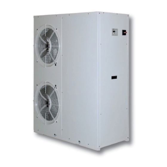
- Page 1 LAB 07M LAB 09M LAB 11M Installation and Operating Instructions Air-to-Water Heat Pump for Outdoor Installation FD 8910...
-
Page 3: Table Of Contents
9.1 External hydraulic circuit recommended.................... EN-11 9.2 LAB recommended hydraulic circuit (°) ..................... EN-11 10 Hydraulic and electrical fittings position ................EN-12 10.1 LAB 07M ............................EN-12 10.2 LAB 09M ............................EN-12 10.3 LAB 11M ............................EN-13 11 Electric connections ........................ EN-14 12 Initial Start-up ........................... - Page 4 14 Pressure drops .........................EN-17 14.1 Pressure drops in heating functioning mode..................EN-17 14.2 Pressure drops (filter) ........................EN-17 15 Sound data ..........................EN-18 15.1 Functioning in cooling mode ......................EN-18 16 Calibration of safety and control parameters ................EN-18 16.1 Control parameters ..........................EN-18 16.2 Protection device calibration ......................
-
Page 5: Warnings Regarding The Documentation
NOTE switching off the master switch at the distribution board and Dimplex will not assume any responsibility for damage caused due to also the main power switch on the product casing. failure to comply with these instructions. -
Page 6: Safety Precautions And Regulations
It is strictly prohibited to stand below the NOTE unit, during lifting. Dimplex will not assume any responsibility for damage due to failure to follow these instructions. Before beginning any work, READ THESE 3.2 Position INSTRUCTIONS CAREFULLY AND CARRY OUT THE SAFETY CHECKS. -
Page 7: Minimum Maintenance Area
Electric resistances of the compressors are supplied as standard with all models. The LAB heat pumps can be used in: under floor heating Radiators Mod. MINIMUM TECHNICAL SPACES Fan Convectors Domestic Hot water productions A mixture of all of the above www.dimplex.de EN-5... -
Page 8: Desription Of Components
Desription of Filter drier Mechanical dehydrator filter that removes impurities and any components traces of humidity present in the refrigerant circuit. Liquid indicator Main components Used to check the refrigerant gas load and any presence of hu- midity in the refrigerant circuit. Solenoid valve The valve closes when the compressor switches off, blocking the flow of refrigerant gas to the evaporator. -
Page 9: Safety And Control Components
Alarm on the Δt Control board ON/OFF external contact Controls all aspects of the heat pump operation. Season switching from external contact. For further informa- tion on this function please contact Dimplex technical de- 5.6 Electronic control partment. Modu-Control The controller allows:... -
Page 10: Selection Criteria
Selection criteria 6.1 Selection criteria The units, are not suitable for installation in salty environments with out an aditional treatment to the heat exchanger. The maxi- mum and minimum limits for water flow rate to the heat ex- changer are indicated by the pressure drop diagram curves. For functioning limits, please refer to the below diagrams, valid for Δt = 5 °C. -
Page 11: Technical Data
Technical data Technical data version with pump 1~230 V - 50 Hz Floor heating (1) LAB 07M LAB 09M LAB 11M Heating capacity 6.86 9.45 11.06 Total input power 2.08 2.86 3.25 Water flow rate 1180 1630 1900 Useful heads kW/kW 3.30... -
Page 12: Anti-Vibration Mounts Position
Anti-vibration mounts Heating (1) Floor system position Inlet water temperature: 30°C Output water temperature: 35°C The anti-vibration mounts are available as an optional extra. External ait temperature: 7°C (B.S.) / 6°C (B.U.) Each kit includes four anti-vibration mounts along with the fasten- Δt: 5°C ers necessary for assembly. -
Page 13: Hydraulic Circuit
Failure Safety valve to comply with this will invalidate the warranty. Expansion vessel (if 2 l are not sufficient) 3-way valve Hot water thermostat Flange heater DHW with external control www.dimplex.de EN-11... -
Page 14: Hydraulic And Electrical Fittings Position
10 Hydraulic and electrical fittings position 10.1 LAB 07M Bx (mm) By (mm) 10.2 LAB 09M Bx (mm) By (mm) EN-12... -
Page 15: Lab 11M
10.3 10.3 LAB 11M Bx (mm) By (mm) www.dimplex.de EN-13... -
Page 16: Electric Connections
Power Sect A Sect B Earth supply Model (mm^2) (mm^2) (mm^2) voltage LAB 07M 230 V LAB 09M 230 V LAB 11M 230 V Key: Sect A = Power supply Sect B = Remote panel IL = Line switch NOTE Check the tightening of all power wire clamps on commissioning and after 30 days from start-up. -
Page 17: Hydraulic Cicuit Controls
Operation with glycol/water fluid, with a percentage of glycol chosen based on the minimum outdoor temperature ex- pected. In this case you must take into account the different outputs and absorption of the chiller, the sizing of the pumps, and the output of the terminals. www.dimplex.de EN-15... - Page 18 13.1 Initial rates for “EXTERNAL AIR TEMPERATURE” and “TEMPERATURE OF PRODUCED WATER”, are not directly related, therefore it is not possible to refer to the curve of one of these rates to obtain corresponding point on the curve of the other rate. Key: FcGPf Corrective factors for cooling capacity...
-
Page 19: Pressure Drops
14.2 14 Pressure drops 14.1 Pressure drops in heating functioning mode 14.2 Pressure drops (filter) Model LAB 07M LAB 09M LAB 11M Ø Filter 1" 1" 1" www.dimplex.de EN-17... -
Page 20: Sound Data
15 Sound data Sound power Dimplex determines sound power values in agreement with 9614 standard, in compliance with that requested by Eurovent certifi- cation. Sound Pressure The Sound pressure is measured in free field conditions at 10m from unit, in compliance with ISO 3744 regulations. -
Page 21: Control Logic For The Compensation Set-Point
Clean the water filter. Bleed the air from the circuit. Verify that the water flow rate to the evaporator is constant. Verify the thermal insulation of the hydraulic piping. Check the percentage of glycol where necessary. www.dimplex.de EN-19... -
Page 22: Disposal
19 Disposal 20 Improper use The appliance is designed and constructed to guarantee the 19.1 Disconnecting the unit maximum safety in its immediate vicinity (IP24), as well as to re- sist atmospheric agents. The fans are protected from involuntary The operations for disconnecting the unit must be carried out by intrusion by means of protective grids.Accidental opening of the a qualified technician.Before disconnecting the unit, the following electric control board with the machine in operation is prevented... -
Page 23: Declaration Of Conformity
21 Declaration of Conformity www.dimplex.de EN-21... - Page 24 Glen Dimplex Deutschland GmbH Subject to alterations and errors. Geschäftsbereich Dimplex Am Goldenen Feld 18 +49 (0) 9221 709 565 D-95326 Kulmbach www.dimplex.de...