
Related Manuals for MSI MS-6368


Summary of Contents for MSI MS-6368
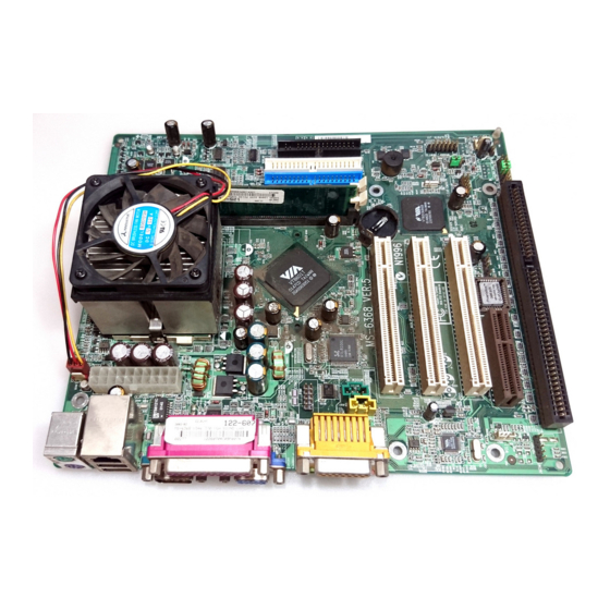
- Page 1 MICRO-STAR INTERNATIONAL MS-6368 Micro-ATX Mainboard Version 5.0 G52-MA00463...
- Page 2 Shielded interface cables and A.C. power cord, if any, must be used in order to comply with the emission limits. VOIR LA NOTICE D’INSTALLATION AVANT DE RACCORDER AU RESEAU. Micro-Star International MS-6368 Tested to comply with FCC Standard For Home or Office Use...
- Page 3 Edition October 2001 Copyright Notice The material in this document is the intellectual property of MICRO- STAR INTERNATIONAL. We take every care in the preparation of this document, but no guarantee is given as to the correctness of its contents. Our products are under continual improvement and we re- serve the right to make changes without notice.
-
Page 4: Safety Instructions
Safety Instructions Always read the safety instructions carefully. Keep this User’s Manual for future reference. Keep this equipment away from humidity. Lay this equipment on a reliable flat surface before setting it up. The openings on the enclosure are for air convection hence protects the equipment from overheating. -
Page 5: Table Of Contents
CONTENTS Chapter 1. Introduction ................1-1 Mainboard Specification ..............1-2 Mainboard Layout ................1-4 Quick Components Guide ..............1-5 Key Features ..................1-6 Chapter 2. Hardware Setup ..............2-1 Central Processing Unit: CPU .............. 2-2 CPU Installation Procedures ............2-2 CPU Core Speed Derivation Procedure ......... - Page 6 Case Connector: JFP1 ..............2-14 Wake On Ring Connector: JMDM1 ..........2-16 Wake On LAN Connector: WOL1 ..........2-16 Fan Power Connectors: CPUFAN/SYSFAN ........ 2-17 CD-In/Aux Line-In/Modem-In Connector: CD_IN/AUX_IN/ MODEM_IN ................2-18 IrDA Infrared Module Connector: JIR1 ........2-19 Front Panel Audio Connector: FRONT AUDIO ......2-20 Jumpers ....................
- Page 7 Set Supervisor/User Password ............3-34 Save & Exit Setup ................3-36 Exit Without Saving ................3-37 Chapter 4. Installing Drivers ..............4-1 VIA Driver Installation for Windows® 98SE/2000/ME/NT4.0 ....4-2 Realtek® 8100L Fast Ethernet Controller ..........4-4 Glossary ....................G-1...
-
Page 8: Chapter 1. Introduction
Introduction C h a p t e r 1 . Introduction Thank you for purchasing the MS-6368 (v5.X) Micro-ATX ® motherboard. The mainboard, based on VIA Apollo PLE133T (VT8601T & VT82C686B) chipsets, is a high-performance computer mainboard ® ® designed for Intel Celeron/Pentium III (including Tualatin)/VIA C3™... -
Page 9: Mainboard Specification
Chapter 1 Mainboard Specification ® Socket 370 for Intel Celeron™ / Tualatin / Pentium III (FC-PGA) proces- sor and VIA C3™ processor Supports 500MHZ, 533MHz., 550MHz, 667MHz, 700Mhz, 750MHz, 800MHz, 850MHz, 933MHz, 950MHz, 1GHz, 1.13GHz, 1.2GHz and above Chipset ® PLE133T VT8601T chipset (552 BGA) - FSB @133MHz - Integrated Trident Blade 2D/3D video accelerator... - Page 10 Introduction On-Board IDE ® An IDE controller on the VIA VT82C686B chipset provides IDE HDD/ CD-ROM with PIO, Bus Master and Ultra DMA 33/66/100 operation modes. Can connect up to four IDE devices Audio Audio controller integrated in 686B chipset SW Audio Codec VIA 1611A - Front Audio Pin Header onboard Network...
-
Page 11: Mainboard Layout
COM 2 VT8601T Top : Game Port Bottom: Line-Out Line-In PCI Slot 1 BATT PCI Slot 2 VT82C 686B JFP1 Codec PCI Slot 3 JBIOS WOL1 BIOS USB2 SYSFAN JIR1 JMDM1 Front Audio ISA (Optional) JBIOS1 MS-6368 (v5.X) Micro-ATX Mainboard... -
Page 12: Quick Components Guide
Introduction Quick Components Guide Component Function Reference DIMM 1~2 Installing memory modules See p. 2-4~2-5 Socket 370 Installing CPU See p. 2-2~2-3 CPUFAN Connecting to CPUFAN See p. 2-17 SYSFAN Connecting to SYSFAN See p. 2-17 ATX Power Supply Installing power supply See p. -
Page 13: Key Features
Chapter 1 Key Features Micro-ATX Form Factor ® ® CPU: Socket 370 for Intel Celeron /Pentium III (including Tualatin)/ VIA C3™ Processor Memory: 2 SDRAM DIMMs Slot: 1 CNR slot, 3 PCI slots, 1 ISA slot (optional) I/O: 2 serial ports (COM2 is the onboard pin header), 1 parallel port, 4 USB ports, 1 floppy port, 1 IrDA connector, 1 Audio/Game port, 1 VGA port, 1 LAN jack (optional) LAN Wake up Function... -
Page 14: Chapter 2. Hardware Setup
Hardware Setup Chapter 2. Hardware Setup Hardware Setup This chapter provides you with the information about hardware setup procedures. While doing the installation, be careful in holding the compo- nents and follow the installation procedures. For some components, if you install in the wrong orientation, the components will not work properly. -
Page 15: Central Processing Unit: Cpu
Chapter 2 Central Processing Unit: CPU ® ® The mainboard supports Intel Celeron™, Pentium III (including Tualatin) and VIA C3™ processor. The mainboard uses a CPU socket called Socket 370 for easy CPU installation. Make sure the CPU has a Heat Sink and a cooling fan attached on top to prevent overheating. -
Page 16: Cpu Core Speed Derivation Procedure
Hardware Setup CPU Core Speed Derivation Procedure The mainboard can automatically set the CPU Host Bus Frequency Clock. CPU Clock 100MHz Core/Bus ratio then CPU core speed Host Clock x Core/Bus ratio 100MHz x 7 700MHz Overclocking This motherboard is designed to support overclocking. However, please make sure your components are able to WARNING! tolerate such abnormal setting, while doing overclocking. -
Page 17: Memory
Chapter 2 Memory The mainboard supports a maximum memory size of 1GB. It provides two 168-pin unbuffered SDRAM DIMM (Double In-Line Memory Module) sockets and supports 64MB to 512MB technology. Introduction to SDRAM Synchronous DRAM (SDRAM) is a type of dynamic RAM memory chip that has been widely used starting in the latter part of the 1990s. -
Page 18: Dimm Modules Combination
Hardware Setup DIMM Modules Combination At least one DIMM module should be installed on the motherboard. Memory modules can be installed on the slots in any order. The single-/ double-sided module each DIMM slot supports is listed below: Socket Memory Module Total Memory DIMM 1 64MB ~ 512MB... -
Page 19: Power Supply
Chapter 2 Power Supply The mainboard supports ATX power supply for the power system. Before connecting to the power supply, always make sure that all components are installed properly and no damage will be caused. ATX 20-Pin Power Supply This connector allows you to connect to an ATX power supply. To connect to the ATX power supply, make sure the power supply connector is installed in the right orientation and the pins are aligned. -
Page 20: Back Panel
Hardware Setup Back Panel The Back Panel provides the following connectors: Mouse Parallel Midi/Joystick Keyboard USB COM 1 L-out L-in Mouse Connector ® The mainboard provides a standard PS/2 mouse mini DIN connector ® ® for attaching a PS/2 mouse. You can plug a PS/2 mouse directly into this connector. -
Page 21: Keyboard Connector
Chapter 2 Keyboard Connector ® The mainboard provides a standard PS/2 keyboard mini DIN connec- ® ® tor for attaching a PS/2 keyboard. You can plug a PS/2 keyboard directly into this connector. Pin Definition SIGNAL DESCRIPTION Keyboard DATA Keyboard DATA No connection Ground Keyboard Clock... -
Page 22: Parallel Port Connector
Hardware Setup Parallel Port Connector The mainboard provides a 25-pin female centronic connector for LPT. A parallel port is a standard printer port that supports Enhanced Parallel Port (EPP) and Extended Capabilities Parallel Port (ECP) mode. Pin Definition SIGNAL DESCRIPTION STROBE Strobe DATA0... -
Page 23: Serial Port Connector: Com 1 & Com 2
Chapter 2 Serial Port Connector: COM 1 & COM 2 The mainboard has one 9-pin male DIN connector COM 1 and one 9-pin COM 2 pin header, which allows you to attach a serial port bracket. You can attach a serial mouse or other serial devices to serial ports. 1 2 3 4 5 Pin Definition SIGNAL... -
Page 24: Joystick/Midi Connectors
Hardware Setup Joystick/Midi Connectors You can connect a joystick or game pad to this connector. Audio Port Connectors Line Out is to connect speakers or headphones. Line In is a connector for external CD player, Tape player or other audio devices. Mic is used to connect to a microphone. -
Page 25: Floppy Disk Drive Connector: Fdd
Chapter 2 Connectors The mainboard provides connectors to connect to FDD, IDE HDD, case, modem, LAN, USB Ports, IR module and CPU/System FAN. Floppy Disk Drive Connector: FDD The mainboard provides a standard floppy disk drive connector that supports 360K, 720K, 1.2M, 1.44M and 2.88M floppy disk types. USB Front Panel Connector: USB2 The mainboard provides one Front USB (Universal Serial Bus) pin header that allows you to connect optional USB ports for Front Panel. -
Page 26: Hard Disk Connectors: Ide1 & Ide2
Hardware Setup Hard Disk Connectors: IDE1 & IDE2 ® The mainboard uses an IDE controller on the VIA VT82C686B chipset that provides PIO mode 0-4, Bus Master, and Ultra DMA 33/66/100 modes. It has two HDD connectors IDE1 (Primary) and IDE2 (Secondary). You can connect up to four hard disk drives, CD-ROM or 120MB Floppy to IDE1 and IDE2. -
Page 27: Power Switch
Chapter 2 Case Connector: JFP1 The case connector block JFP1 allows you to connect to the Power Switch, Reset Switch, Speaker, Power LED and HDD LED on the case. Reset Switch Power Switch Speaker Power JFP1 JFP1 Pin Definition Description Description HDD+ HDD-... - Page 28 Hardware Setup Reset Switch Reset switch is used to reboot the system rather than turning the power ON/ OFF. Avoid rebooting while the HDD is working. You can connect the Reset switch from the system case to this pin. Power LED The Power LED is lit while the system power is on.
-
Page 29: Wake On Ring Connector: Jmdm1
Chapter 2 Wake On Ring Connector: JMDM1 This connector allows you to connect to a modem card with Wake On Ring function. The connector will power up the system when a signal is received through the modem card. MDM_WAKEUP 5VSB JMDM1 Wake On LAN Connector: WOL1 This connector allows you to connect to a LAN card with Wake On... -
Page 30: Fan Power Connectors: Cpufan/Sysfan
Hardware Setup Fan Power Connectors: CPUFAN/SYSFAN The CPUFAN (processor fan) and SYSFAN (system fan) support system cooling fan with +12V. It supports three-pin head connector. When connecting the wire to the connectors, always take note that the red wire is the positive and should be connected to the +12V, the black wire is Ground and should be connected to GND. -
Page 31: Modem_In
Chapter 2 CD-In/Aux Line-In/Modem-In Connector: CD_IN/AUX_IN/ MODEM_IN CD_IN connector is for CD-ROM audio connector. AUX_IN connector is for DVD add-on card with Line-in connector. MODEM_IN connector is for modem with internal audio connector. Mono_Out Phone_In MODEM_IN AUX_IN CD_IN Note: Mono_Out is connected to the Modem speaker-out connector. Phone_In is connected to the Modem Microphone-In connector. -
Page 32: Irda Infrared Module Connector: Jir1
Hardware Setup IrDA Infrared Module Connector: JIR1 This connector allows you to connect an IrDA Infrared module. You must configure the setting through the BIOS setup to use the IR function. JIR1 Pin Definition Signal IRRX IRTX 2-19... -
Page 33: Front Panel Audio Connector: Front Audio
Chapter 2 Front Panel Audio Connector: FRONT AUDIO You can connect an optional audio connector to the Front Panel Audio Header. FRONT AUDIO Description Description Active Line Out (R) Active Line Out (L) GND (ALO) GND (ALO) GND (+12) GND (+12) +12V (1A) GND (MIC) Front Line Out (R) - Page 34 Hardware Setup Note: To have the Line-out connector on the back panel work properly, you need to place the jumper on the pin# 11~14 of the FRONT AUDIO connector. Otherwise, this Line-out connector will not function and nothing can be heard through speakers or headphones attached to the connector.
-
Page 35: Jumpers
Chapter 2 Jumpers The motherboard provides the following jumpers for you to set the computer’s function. This section describes how to change your motherboard’s function through the use of jumpers. Clear CMOS Jumper: JBIOS There is a CMOS RAM on board that has a power supply from external battery to keep the data of system configuration. -
Page 36: Bios Flash Jumper: Jbios1
Hardware Setup BIOS Flash Jumper: JBIOS1 This jumper is used to lock or unlock the boot block area on BIOS. When unlocked, the BIOS boot block area can be updated. When locked, the BIOS boot block area can not be updated. JBIOS1 BIOS Flash Unlocked BIOS Flash Locked... -
Page 37: Slots
Chapter 2 Slots The motherboard provides three 32-bit Master PCI Bus Slots, one CNR and one optional ISA slot. PCI Slots CNR Slot ISA Slot (Optional) PCI Slots Three PCI slots allow you to install expansion cards to meet your needs. When adding or removing expansion cards, make sure that you unplug the power supply first. -
Page 38: Pci Interrupt Request Routing
Hardware Setup PCI Interrupt Request Routing The IRQ, abbreviation of interrupt request line and pronounced I-R-Q, are hardware lines over which devices can send interrupt signals to the microprocessor. The PCI/USB/AC97 IRQ pins are typically connected to the PCI bus INTA#-INTD# pins as follows: Order 1 Order 2 Order 3 Order 4 PCI Slot 1 INT A# INT B# INT C# INT D# PCI Slot 2 INT B# INT C# INT D# INT A#... - Page 39 ® AWARD BIOS Setup C h a p t e r ® AWARD B I O S Setup ® AWARD BIOS Setup ® The mainboard uses AWARD BIOS ROM that provides a Setup util- ity for users to modify the basic system configuration. The information is stored in a battery-backed CMOS RAM so it retains the Setup information when the power is turned off.
-
Page 40: Entering Setup
Chapter 3 Entering Setup Power on the computer and the system will start POST (Power On Self Test) process. When the message below appears on the screen, press <DEL> key to enter Setup. Hit DEL if you want to run SETUP If the message disappears before you respond and you still wish to enter Setup, restart the system by turning it OFF and On or pressing the RESET button. -
Page 41: Getting Help
® AWARD BIOS Setup Getting Help After entering the Setup utility, the first screen you see is the Main Menu. Main Menu The main menu displays the setup categories the BIOS supplies. You can use the arrow keys ( ↑↓ ) to select the item. The on-line description for the selected setup category is displayed on the bottom of the screen. -
Page 42: The Main Menu
Chapter 3 The Main Menu ® Once you enter AWARD BIOS CMOS Setup Utility, the Main Menu will appear on the screen. The Main Menu displays eleven configurable functions and two exit choices. Use arrow keys to move among the items and press <Enter>... - Page 43 ® AWARD BIOS Setup PnP/PCI Configurations This entry appears if your system supports PnP/PCI. PC Health Status This entry displays the current status of your PC. Frequency/Voltage Control Use this menu to specify your settings for frequency/voltage control. Load Fail-Safe Defaults Use this menu to load the BIOS default values for the minimal/stable per- formance of your PC.
-
Page 44: Standard Cmos Features
Chapter 3 Standard CMOS Features The items inside Standard CMOS Features menu are divided into 13 categories. Each category includes none, one or more setup items. Use the arrow keys to highlight the item you want to modify and use the <PgUp> or <PgDn>... - Page 45 ® AWARD BIOS Setup IDE Primary Master/Primary Slave/Secondary Master/Secondary Slave Press PgUp/<+> or PgDn/<-> to select the hard disk drive type. The specification of hard disk drive will show up on the right hand according to your selection. Access Mode The settings are Auto, CHS, LBA and Large.
- Page 46 Chapter 3 boot. Available options are: All Errors The system stops when any error is detected. No Errors The system doesn’t stop for any detected error. All, But Keyboard The system doesn’t stop for a keyboard error. All, But Diskette The system doesn’t stop for a disk error.
-
Page 47: Advanced Bios Features
® AWARD BIOS Setup Advanced BIOS Features Anti-Virus Protection The item is to set the Virus Warning feature for IDE Hard Disk boot sector protection. If the function is enabled and any attempt to write data into this area is made, BIOS will display a warning message on screen and beep. Settings: Disabled and Enabled. - Page 48 Chapter 3 for error detection and correction when data passes through L2 cache memory. Settings: Enabled and Disabled. Processor Number Feature ® This feature is for Pentium !!! only. When set to Enabled, the system will check CPU Serial Number. Set to Disabled if you don’t want the system to know the CPU Serial Number.
- Page 49 ® AWARD BIOS Setup process: the drive activity light will come on and the head will move back and forth once. Settings: Enabled and Disabled. Boot Up NumLock Status This item is to set the Num Lock status when the system is powered on. Setting to On will turn on the Num Lock key when the system is powered on.
- Page 50 Chapter 3 Option Description Setup The password prompt appears only when end users try to run Setup. System A password prompt appears every time when the com- puter is powered on or when end users try to run Setup. APIC Mode This field is used to enable or disable the APIC (Advanced Programmable Interrupt Controller).
-
Page 51: Advanced Chipset Features
® AWARD BIOS Setup Advanced Chipset Features Note: Change these settings only if you are familiar with the chipset. DRAM Timing By SPD Selects whether DRAM timing is configured by reading the contents of the SPD (Serial Presence Detect) device on the DRAM module. Setting to Enabled makes both SDRAM Cycle Length and DRAM Clock automatically determined by BIOS according to the configurations on the SPD. - Page 52 Chapter 3 HCLK-33M The DRAM clock will be equal to the Host Clock minus 33MHz. For example, if the Host Clock is 133MHz, the DRAM clock will be 100MHz. HCLK+33M The DRAM clock will be equal to the Host Clock plus 33MHz.
- Page 53 ® AWARD BIOS Setup Frame Buffer Size Frame Buffer is the video memory that stores data for video display (frame). This field is used to determine the memory size for Frame Buffer. Larger frame buffer size increases video performance. Settings: 2M, 4M and 8M. AGP Aperture Size Selects the size of the Accelerated Graphics Port (AGP) aperture.
- Page 54 Chapter 3 PCI Dynamic Bursting When Enabled, every write transaction goes to the write buffer. Then burstable transactions burst on the PCI bus and nonburstable transactions do not. PCI Master 0 WS Write When Enabled, writes to the PCI bus are executed with zero wait state. PCI Delay Transaction The chipset has an embedded 32-bit posted write buffer to support delay transactions cycles so that transactions to and from ISA bus are buffered...
-
Page 55: Integrated Peripherals
® AWARD BIOS Setup Integrated Peripherals OnChip IDE Channel0/1 The integrated peripheral controller contains an IDE interface with support for two IDE channels. Choose Enabled to activate each channel separately. IDE Prefetch Mode The onboard IDE drive interfaces supports prefetching, for faster drive accesses. - Page 56 Chapter 3 cally determines the best mode for each IDE device. Primary/Secondary Master/Slave UDMA Ultra DMA implementation is possible only if your IDE device supports it and your operating environment contains a DMA driver. If both your hard drive and software support Ultra DMA, select Auto to enable BIOS support. Init Display First This item specifies which VGA card is your primary graphics adapter.
- Page 57 ® AWARD BIOS Setup Default is Auto. If you have ISA add-on card, the suggested configuration is as the following: If the ISA add-on card has Onboard Serial port to be set at COM4 COM3 COM2 COM1 PORT1 PORT2 (I/O:2E8H) ASSIGNED (I/O:3E8H) ASSIGNED...
- Page 58 Chapter 3 TX, RX inverting enable This item allows you to enable the TX, RX inverting which depends on different H/W requirement. This field is not recommended to change its default setting for avoiding any error in your system. Settings are “No, Yes”, “Yes, No”, “Yes, Yes”...
- Page 59 ® AWARD BIOS Setup Parallel Port EPP Type The item selects the EPP version used by the parallel port if the port is set to EPP or ECP/EPP mode. Settings: EPP1.7 and EPP1.9. Onboard Legacy Audio The item enables or disables the onboard audio features of the mainbaord and the following audio options in the BIOS.
-
Page 60: Power Management Setup
Chapter 3 Power Management Setup ACPI function This item is to activate the ACPI (Advanced Configuration and Power Management Interface) Function. If your operating system is ACPI-aware, such as Windows 98SE/2000/ME, select Enabled. Settings: Enabled and Disabled. Power Management Press <Enter> to enter the sub-menu for power management options. 3-22... - Page 61 ® AWARD BIOS Setup Power Management This item is used to select the degree (or type) or power saving and is related to these modes: Doze Mode and Suspend Mode. There are three options for power management: Min Saving Minimum Power Management. Doze Mode = 1 Hour, Suspend Mode = 1 Hour.
- Page 62 Chapter 3 ware maintains all system context. S3(STR) The S3 sleep mode is a power-down state in which power is supplied only to essential components such as main memory and wake-capable devices, and all system context is saved to main memory. The informa- tion stored in main memory will be used to restore PC to previous state when an “wake up”...
- Page 63 ® AWARD BIOS Setup Soft-Off by PWRBTN This feature allows users to configure the power button as a normal power- on/-off button or a soft-off button. Settings are: Instant-Off The power button functions as a normal power-on/- off button. Delay 4 Sec. When you press the power button, the computer enters the suspend/sleep mode, but if the button is pressed for more than four seconds, the computer...
- Page 64 Chapter 3 VGA, LPT & COM, HDD & FDD, PCI Master, PowerOn by PCI Card, Wake Up On LAN/Ring These items specify whether the system will be awakened from power saving modes when activity or input signal of the specified hardware peripheral or component is detected.
- Page 65 ® AWARD BIOS Setup Primary INTR When this is set to ON, any event occurring will wake up the system which has been powered down. IRQ3~IRQ15 Enables or disables the monitoring of the specified IRQ line. If set to Enabled, the activity of the specified IRQ line will prevent the system from entering power saving modes or awaken it from power saving modes.
-
Page 66: Pnp/Pci Configurations
Chapter 3 PnP/PCI Configurations PNP OS Installed When set to YES, BIOS will only initialize the PnP cards used for booting (VGA, IDE, SCSI). The rest of the cards will be initialized by the PnP operat- ® ing system like Windows 95 or 98. - Page 67 ® AWARD BIOS Setup Manual. Press <Enter> and you will enter the sub-menu of the items. IRQ Resources & DMA Resources list IRQ-3/-4/-5/-7/-9/-10/-11/-12/-14/-15 and DMA-0/-1/-3/-5/-6/-7 for users to set each IRQ/DMA a type depending on the type of device using the IRQ/DMA. Settings are: PCI/ISA PnP For Plug &...
-
Page 68: Pc Health Status
Chapter 3 PC Health Status This section is to monitor the current hardware status including CPU temperature, CPU Fan speed, Vcore etc. This is available only if there is hardware monitoring onboard. Current CPU Temp., Current System Temp., Current CPU/System Fan Speed, Vcore, 2.5/3.3/5/12V These items display the current status of all of the monitored hardware devices/components such as CPU voltages, temperatures and all fans’s... -
Page 69: Frequency/Voltage Control
® AWARD BIOS Setup Frequency/Voltage Control Auto Detect DIMM/PCI Clk This item is used to auto detect the DIMM/PCI slots. When set to Enabled, the system will remove (turn off) clocks from empty DIMM/PCI slots to minimize the electromagnetic interference (EMI). Settings: Enabled and Disabled. -
Page 70: Load Fail-Safe/Optimized Defaults
Chapter 3 Load Fail-Safe/Optimized Defaults The two options on the main menu allow users to restore all of the BIOS settings to the default Fail-Safe or Optimized values. The Optimized Defaults are the default values set by the mainboard manufacturer specifically for the optimal performance of the mainboard. - Page 71 ® AWARD BIOS Setup When you select Load Optimized Defaults, a message as below appears: Pressing Y loads the default factory settings for optimal system performance. 3-33...
-
Page 72: Set Supervisor/User Password
Chapter 3 Set Supervisor/User Password When you select this function, a message as below will appear on the screen: Type the password, up to eight characters in length, and press <Enter>. The password typed now will clear any previously set password from CMOS memory. - Page 73 ® AWARD BIOS Setup enter Setup. About Supervisor Password & User Password: Supervisor password : Can enter and change the settings of the setup menu. User password: Can only enter but do not have the right to change the settings of the setup menu.
-
Page 74: Save & Exit Setup
Chapter 3 Save & Exit Setup When you want to quit the Setup menu, you can select this option to save the changes and quit. A message as below will appear on the screen: Typing Y will allow you to quit the Setup Utility and save the user setup changes to RTC CMOS. -
Page 75: Exit Without Saving
® AWARD BIOS Setup Exit Without Saving When you want to quit the Setup menu, you can select this option to abandon the changes. A message as below will appear on the screen: Typing Y will allow you to quit the Setup Utility without saving any changes to RTC CMOS. -
Page 76: Chapter 4. Installing Drivers
Installing Drivers Chapter 4. Installing Drivers Installing Drivers The chapter describes how to install drivers for VIA chipset, AC97 ® audio, VGA and Realtek 8100 fast ethernet controller, and the basic system requirements for driver installation. To install the drivers correctly, you must install VIA chipset driver prior to other drivers. -
Page 77: Via Driver Installation For Windows 98Se/2000/ Me/Nt4.0
Chapter 4 ® VIA Driver Installation for Windows 98SE/2000/ ME/NT4.0 ® Note 1: Install Windows 2000 Service Pack2 or the latest version be- ® fore installing the VIA drivers into Windows 2000. ® Note 2: Install Windows NT4.0 Service Pack 6 or above before install- ®... - Page 78 Installing Drivers One Touch Setup: In Windows 2000/ME, you may see the One Touch Setup button appear on the setup screen. Choosing the button will help you to install more than one driver into the system without going through the installation process step by step and save a lot of time accordingly.
-
Page 79: Realtek 8100L Fast Ethernet Controller
Chapter 4 ® Realtek 8100L Fast Ethernet Controller ® When your mainboard comes with the Realtek 8100L LAN ® controller, you must install the Realtek LAN driver to support the LAN ® function. The Realtek 8100L is a sophisticated 32-bit PCI component, with enhanced scatter-gather bus mastering capabilities. - Page 80 Installing Drivers ® Installation for Windows NT4.0 Insert the supplied CD disk into the CD-ROM drive. Copy all files under CD-ROM drive:\Network\Realtek\8139\Winnt4 to your hard disk. For example, copy the files to C:\Lan. Right click on Network Neighborhood. Select Properties. Click Yes to install the driver.