
Related Manuals for Foxconn G41MD Series


Summary of Contents for Foxconn G41MD Series
- Page 1 Инструкция для материнской платы Foxconn G41MD Перейти в карточку товара 8 800 775 98 98...
- Page 2 G41MD Series Motherboard User’s Manual...
- Page 3 Statement: This manual is the intellectual property of Foxconn, Inc. Although the information itself to inform the user of these changes. Trademark: All trademarks are the property of their respective owners. Version: User’s Manual V1.0 for G41MD Series motherboard. P/N: 3A222NF00-000-G...
-
Page 4: Declaration Of Conformity
Declaration of conformity HON HAI PRECISION INDUSTRY COMPANY LTD 66 , CHUNG SHAN RD., TU-CHENG INDUSTRIAL DISTRICT, TAIPEI HSIEN, TAIWAN, R.O.C. declares that the product G41MD Motherboard is in conformity with accordance with 89/336 EEC-EMC Directive) disturbance characteristics of information technology equipment Part 3: Limits Section 2: Limits for harmonic current emissions... - Page 5 Declaration of conformity Trade Name: FOXCONN Model Name: G41MD Responsible Party: PCE Industry Inc. Telephone: 714-738-8868 Facsimile: 714-738-8838 Type of Product: Motherboard Manufacturer: HON HAI PRECISION INDUSTRY COMPANY LTD Address: 66 , CHUNG SHAN RD., TU-CHENG INDUSTRIAL DISTRICT, TAIPEI HSIEN, TAIWAN, R.O.C.
-
Page 6: Installation Precautions
Installation Precautions comes out as a spark which will quickly damage your electronic equipment. Please wear an electrostatic discharge (ESD) wrist strap when handling components such as a motherboard, CPU or memory. CPU, memory, expansion cards or other peripherals. It is recommended to unplug the AC power cord from the power supply outlet. -
Page 7: Table Of Contents
Table of Contents Chapter 1 Product Introduction ................2 Layout.......................4 Back Panel Connectors ................Chapter 2 Hardware Install Install the CPU and CPU Cooler ..............8 Install the Memory .................. 11 Install an Expansion Card ..............13 Install other Internal Connectors ............14 Jumpers ....................17 Install driver and utility ................20 Chapter 3 BIOS Setup Enter BIOS Setup ...................23... - Page 8 Technical Support : Support Website : http://www.foxconnchannel.com Support Website : http://www.foxconnsupport.com Worldwide online contact Support : http://www.foxconnsupport.com/inquiry.aspx CPU Support List : http://www.foxconnsupport.com/cpusupportlist.aspx Memory, VGA Compatibility List : http://www.foxconnsupport.com/complist.aspx...
- Page 9 Thank you for buying Foxconn G41MD Series motherboard. Foxconn products are engineered to maximize computing power, providing only what you need for break-through performance. With advanced overclocking capability and a range of connectivity features for today multi-media computing requirements, G41MD enables you to unleash more power from your computer.
- Page 10 ® For the latest CPU information, please visit: http://www.foxconnchannel.com North Bridge: Intel ® G41 Chipset North Bridge: Intel South Bridge: Intel ® ICH7 Memory 2 x 240-pin DDR3 DIMM sockets Support up to 8GB of system memory Dual channel DDR3 1333(oc*)/1066/800 MHz architecture(*:Overclocking) Expansion Slots 1 x PCI Express x16 slot x16 slot...
- Page 11 Back Panel 1 x PS/2 Keyboard port Connectors 1 x PS/2 Mouse port 1 x PS/2 Mouse port 1 x Serial port 1 x Serial port 1 x Parallel port (optional) 1 x VGA port 4 x USB 2.0 ports 6-channel Audio Ports Hardware Monitor System voltage detection...
-
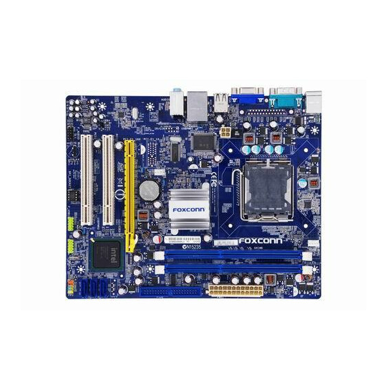
Page 12: Layout
1-2 Layout 12. South Bridge: Intel ® ICH7 1. 4-pin ATX 12V Power Connector 2. USBPWR1 Jumper 13. Front Panel Connector 14. SATA Connectors 4. SYS_FAN Header 16. 24-pin ATX Power Connector 6. PCI Express x16 Slot 17. DDR3 DIMM Slots 7. -
Page 13: Back Panel Connectors
1-3 Back Panel Connectors PS/2 Mouse Port LAN Port Line In Line Out Microphone In PS/2 Keyboard Port Serial Port VGA Port USB Ports Audio Ports 1. PS/2 Mouse Port Use the upper port (green) to connect a PS/2 mouse. 2. - Page 14 Left: Active Right: Link Active Link LAN Type Status Description Status Description No Link No Link 10 Mb/s Connection 1000M Green Data Green 100 Mb/s Connection Blinking Activity Orange 1000 Mb/s Connection...
- Page 15 This chapter introduces the hardware installation process, including the installation of the CPU, memory, power supply, slots, pin headers and the mounting of jumpers. Caution should be exercised during the installation of these modules. Please refer to the motherboard layout prior to any installation and read the contents in this chapter carefully.
-
Page 16: Install The Cpu And Cpu Cooler
2-1 Install the CPU and CPU Cooler Read the following guidelines before you begin to install the CPU : installing the CPU to prevent hardware damage. you may locate the notches on both sides of the CPU and alignment keys on the CPU socket.) and damage of the CPU may occur. - Page 17 Follow the steps to install the CPU onto the CPU socket : Before installing the CPU, make sure to turn off the computer and unplug the power cord from the power outlet to prevent damage to the CPU. 1. Remove protective socket cover. Remove protective socket cover.
-
Page 18: Install The Cpu Cooler
Install the CPU Cooler Follow the steps below to correctly install the CPU cooler on the motherboard. (The following procedures use Foxconn cooler as the example.) 1. Apply and spread an even thermal 2. Place the four bolts of the CPU grease on the surface of CPU. -
Page 19: Install The Memory
2-2 Install the Memory Read the following guidelines before you begin to install the memory : of the same capacity, brand, speed, and chips be used. installing the memory to prevent hardware damage. one direction. If you are unable to insert the memory, switch the direction. This motherboard provides two DDR3 memory sockets and supports Dual Channel Technology. - Page 20 Before installing a memory module, make sure to turn off the computer and unplug the power cord from the power outlet to prevent damage to the memory module. Be sure to install DDR3 DIMMs on this motherboard. Notch If you take a look at front side of memory module, it has asymmetric pin counts on both sides correctly install your memory modules into the sockets.
-
Page 21: Install An Expansion Card
2-3 Install an Expansion Card that came with your expansion card. installing an expansion card to prevent hardware damage. PCI Express x16 Follow the steps below to correctly install your expansion card in the expansion slot. 1. Locate an expansion slot that supports your card. Remove the metal slot cover from the chassis back panel. -
Page 22: Install Other Internal Connectors
2-4 Install other Internal Connectors Power Connectors This motherboard uses an ATX power supply. In order not to damage any device, make sure all the devices have been installed properly before applying the power supply. 24-pin ATX Power Connector : PWR1 PWR1 is the ATX power supply connector. - Page 23 Audio Connector : F_AUDIO PORT1_L AUD_GND The audio connector supports HD Audio standard. It PORT1_R PRESENCEJ provides the Front Audio output choice. PORT2_R SENSE1_RETURN SENSE_SEND EMPTY PORT2_L SENSE2_RETURN F_AUDIO SPKJ Speaker Connector : SPEAKER EMPTY The speaker connector is used to connect speaker SPKJ of the chassis.
- Page 24 Front Panel Connector : FP1 This motherboard includes one connector for connecting the front panel switch and LED Indicators. HDD-LED PWR-LED Hard Disk LED Connector (HDD-LED) RESET-SW PWR-SW Connect to the chassis front panel IDE indicator LED. EMPTY It indicates the active status of the hard disks. This 2-pin connector is directional with +/- sign.
-
Page 25: Jumpers
2-5 Jumpers For some features needed, users can change the jumper settings on this motherboard to modify them. This section explains how to use the various functions of this motherboard by changing the jumper settings. Users should read the following content carefully prior to modifying any jumper setting. Description of Jumpers However, in this manual, pin 1 is simply labeled as “1”. - Page 26 connected USB devices. using the connected USB devices. At the same time, a corresponding setting must be set in BIOS as below: Set “CMOS Setup” -> “Power Management Setup” -> “USB Wake Up From S3” to “Enabled”. (Default) USBPWR1/2 USBPWR1 is for the internal USB connectors, USBPWR2 is for the rear USB ports. whether under normal condition or in sleep mode.
- Page 27 When you use the memory which supports 1333/1066, the jumper is used to overclock memory frequency. and make the memory word at 1333MHz. Set the jumper to pins 2-3 (as Status 1) , memory frequency will be 1066MHz. This is default status.
-
Page 28: Install Driver And Utility
Manual Instal- lation Step by Step Automatic Installation by One Click. Exit the program Click to visit Select Select Browse CD Drop to Foxconn's to Install to Install System Tray website Utilities Drivers Choose the items you want to Install... - Page 29 2. Utility Use these options to install additional software programs.
- Page 30 This chapter tells how to change system settings through the BIOS Setup menus. Detailed descriptions of the BIOS parameters are also provided. You have to run the Setup Program when the following cases occur : 1. An error message appears on the screen during the system Power On Self Test (POST) process.
-
Page 31: Enter Bios Setup
Enter BIOS Setup The BIOS is the communication bridge between hardware and software, correctly setting up the BIOS parameters is critical to maintain optimal system performance. Power on the computer, when the message "Press <Del> to enter Setup, <Esc> to boot menu" appears at the bottom of the screen, you can press <DEL>... - Page 32 All the items related with Green function features can be setup through this menu. This setup enables you to read/change fan speeds, and displays temperatures and voltages of your CPU/System. The Supervisor/User password can be set up through this menu to prevent unauthorized use of your computer.
-
Page 33: System Information
System Information and so on. Use the arrow up/down keys to select an item, then use the <+> or <-> keys to change the setting. System Information Halt On Model Name :G41MD BIOS Version :A81F1D04 MAC Address :90-FB-A6-30-0D-91 F9:Optimized Defaults Date <weekday><month><date>... - Page 34 Model name of this product. service people if a BIOS upgrade is needed. This item shows the information of the system memory, determined by POST(Power On Self Test) of the BIOS. This item shows the onboard LAN MAC address.
-
Page 35: Advanced Bios Features
Advanced BIOS Features F9:Optimized Defaults ers design and build CPU architecture systems with two or more processors. MPS 1.1 was MPS 1.4 introduces support for a secondary PCI bus without requiring a PCI bridge. If your operating system comes with support for MPS 1.4, you should keep the setting as the default 1.4. - Page 36 While Enabled, this option allows BIOS to skip certain tests while booting, this will shorten the time needed to boot the system. available settings are: On (default) and Off.
-
Page 37: Fox Central Control Unit Fox Central Control Unit
Fox Central Control Unit Fox Central Control Unit Help Item F9:Optimized Defaults Press <Enter> to go to its submenu. generated by the system, so to comply with FCC regulation. But if overclocking is activated, you had better disable it. This option is used to auto detect PCI slot. When enabled, the system will turn off clock of the empty PCI slot to reduce EMI (Electromagnetic Interference). -
Page 38: Smart Bios
Smart BIOS Smart BIOS Options Current FSB Speed : 1333MHz Disabled Current DRAM Speed : 800MHz Enabled F9:Optimized Defaults Smart Power LED is a feature built on your motherboard to indicate different states during Power-On Self-Test (POST). The LED is located at the front panel, and it displays POST state by different long-short blinking intervals. - Page 39 Help Item Module Version : 3F.0F This should be enabled Manufacturer : Intel in order to enables or disable the “Enhanced Halt State”. FSB Speed :1333MHz Cache L1 :128 KB Cache L2 :6144 KB C1E Support Execute Disable Bit EIST Function F9:Optimized Defaults C1E represents Enhanced HALT State.
- Page 40 Enhanced Intel SpeedStep ® technology (EIST) allows the system to dynamically adjust processor voltage and core frequency, which can result in decreased average power consumption and decreased average heat production. There are some system requirements must be met, including CPU, chipset, motherboard, BIOS and operation system.
-
Page 41: Advanced Chipset Features Advanced Chipset Features
Advanced Chipset Features Advanced Chipset Settings Help Item WARNING: Setting wrong values in below sections Configure North Bridge may cause system to malfunction. features. F9:Optimized Defaults Press <Enter> to go to its submenu. Help Item PCI MMIO Allocation:4GB To 3328MB remapping of remapping of memory. - Page 42 the time the memory controller srart sending commands to memory bank. The lower the value, the sonner the memory controller can send commands out to the activated memory bank. Op- tions are Auto, 1T and 2T. mode. This item is used to enable/disable provision of DRAM timing by SPD device. The Serial Presence Detect (SPD) device is a small EEPROM chip, mounted on a memory module.
- Page 43 Help Item Options Disabled F9:Optimized Defaults C bus. The SMBus speci- superimposed on the I mands and information between the Smart Battery, SMBus Host, Smart Battery Charger, and other SMBus Devices. This item is used to enable/disable System Management Bus controller. SLP_S4# is a signal for power plane control.
-
Page 44: Integrated Peripherals
Integrated Peripherals Help Item device(s) . F9:Optimized Defaults Press <Enter> to go to relative submenu. Help Item Options SATA Controller Disabled Compatible Enhanced F9:Optimized Defaults are displayed as Primary IDE Master/Slave and Secondary IDE Master/Slave in "System SATA drives are displayed as Secondary IDE Master/Slave and Third IDE Master/Slave in "System Information"... - Page 45 OnBoard Configuration OnBoard Configuration Help Item Help Item Options OnBoard Audio Controller OnBoard LAN Controller OnBoard LAN Boot ROM OnBoard LAN Boot ROM Enabled Enabled Disabled F9:Optimized Defaults This item is used to enable or disable the onboard Audio Controller. This item is used to enable or disable the onboard LAN controller.
- Page 46 SuperIO Configuration SuperIO Configuration Help Item Help Item Serial Port1 Address Serial Port1 Mode Addresses . Addresses . Addresses . Addresses . F9:Optimized Defaults This item is used to assign the I/O address and interrupt request (IRQ) for the onboard serial port 1.
- Page 47 Help Item Module Version - 2.24.3-13.4 Enables support for legacy USB. AUTO AUTO USB Devices Enabled : option disables None legacy support if no USB devices are Legacy USB Support connected. USB 2.0 Controller F9:Optimized Defaults This item is used to enable the support for USB devices on legacy OS. If you have a USB keyboard or mouse, set to auto or enabled.
-
Page 48: Power Management Setup
Power Management Setup :Move Enter:Select +/-/:Value F10:Save ESC:Exit F1:General Help F9:Optimized Defaults S1 - The S1 sleeping state is a low wake latency sleeping state. In this state, no system context is lost (CPU or chip set) and hardware maintains all system context. (also called Power On Suspend) S2 - The S2 sleeping state is a low wake latency sleeping state. - Page 49 This item is used to set the energy saving mode of the ACPI function. When you select “S1 (POS)” mode, the power is always on and computer can be resumed at any time. When you select “S3 (STR)” mode, the power will be down after a period of time. The status of the computer before it entering STR will be saved in memory, and the computer can quickly return to previous state when the STR function wakes.
-
Page 50: Pc Health Status
PC Health Status PC Health Status Warning Temperature Help Item Options CPU Temperature C/84 System Temperature C/87 Disabled C/122 CPU Fan Speed :1991 RPM C/131 System Fan Speed :N/A C/140 C/149 DRAM Voltage :1.648 V C/167 +3.30V :3.408 V C/176 +12.0V :12.288 V C/194... -
Page 51: Bios Security Features
BIOS Security Features BIOS Security Features Supervisor Password : Not Installed Help Item User Password : Not Installed Change Supervisor Password Install or change the Change User Password Change User Password password. F9:Optimized Defaults This item is used to install or change supervisor password. Enter New Password : After you input Supervisor password, it then will ask you to input user password optionally. -
Page 52: Load Optimal Defaults
Load Optimal Defaults Optimal defaults are the best settings of this motherboard. Always load the Optimal defaults after updating the BIOS or after clearing the Load Optimal Defaults? CMOS values. Select this option and press Enter, it will pop out a dialogue box to let you load the defaults. - Page 53 материнской платы Foxconn G41MD Описание Характеристики...