Table of Contents
Advertisement
Advertisement
Table of Contents

Related Manuals for Foxconn G41MD


Summary of Contents for Foxconn G41MD
- Page 1 G41MD Series Motherboard User’s Manual...
- Page 2 Statement: This manual is the intellectual property of Foxconn, Inc. Although the information in this manual may be changed or modified at any time, Foxconn does not obligate itself to inform the user of these changes. Trademark: All trademarks are the property of their respective owners.
-
Page 3: Declaration Of Conformity
HON HAI PRECISION INDUSTRY COMPANY LTD 66 , CHUNG SHAN RD., TU-CHENG INDUSTRIAL DISTRICT, TAIPEI HSIEN, TAIWAN, R.O.C. declares that the product G41MD Motherboard is in conformity with (reference to the specification under which conformity is declared in accordance with 89/336 EEC-EMC Directive) ■... - Page 4 Declaration of conformity Trade Name: FOXCONN Model Name: G41MD Responsible Party: PCE Industry Inc. Address: 458 E. Lambert Rd. Fullerton, CA 92835 Telephone: 714-738-8868 Facsimile: 714-738-8838 Equipment Classification: FCC Class B Subassembly Type of Product: Motherboard Manufacturer: HON HAI PRECISION INDUSTRY...
-
Page 5: Installation Precautions
Installation Precautions ■ Electrostatic discharge (ESD) is the sudden and momentary electric current that flows between two objects at different electrical potentials. Normally it comes out as a spark which will quickly damage your electronic equipment. Please wear an electrostatic discharge (ESD) wrist strap when handling components such as a motherboard, CPU or memory. -
Page 6: Table Of Contents
Table of Contents Chapter 1 Product Introduction Product Specifications ................2 Layout.......................4 Back Panel Connectors ................5 Chapter 2 Hardware Install Install the CPU and CPU Cooler ..............8 Install the Memory .................. 11 Install an Expansion Card ..............13 Install other Internal Connectors ............14 Jumpers ....................17 Install driver and utility ................20 Chapter 3 BIOS Setup... - Page 7 Technical Support : Support Website : http://www.foxconnchannel.com Support Website : http://www.foxconnsupport.com Worldwide online contact Support : http://www.foxconnsupport.com/inquiry.aspx CPU Support List : http://www.foxconnsupport.com/cpusupportlist.aspx Memory, VGA Compatibility List : http://www.foxconnsupport.com/complist.aspx...
- Page 8 Thank you for buying Foxconn G41MD Series motherboard. Foxconn products are engineered to maximize computing power, providing only what you need for break-through performance. With advanced overclocking capability and a range of connectivity features for today multi-media computing requirements, G41MD enables you to unleash more power from your computer.
-
Page 9: Product Specifications
1-1 Product Specifications Support LGA 775 socket Intel ® CPU, Max processor power up to 95w For the latest CPU information, please visit: http://www.foxconnchannel.com Front Side Bus 1333/1066/800/533MHz FSB North Bridge: Intel ® G41 Chipset North Bridge: Intel South Bridge: Intel ® ICH7 Memory 2 x 240-pin DDR3 DIMM sockets Support up to 8GB of system memory... - Page 10 Back Panel 1 x PS/2 Keyboard port Connectors 1 x PS/2 Mouse port 1 x PS/2 Mouse port 1 x Serial port 1 x Serial port 1 x Parallel port (optional) 1 x VGA port 4 x USB 2.0 ports 1 x RJ-45 LAN port 6-channel Audio Ports Hardware Monitor...
-
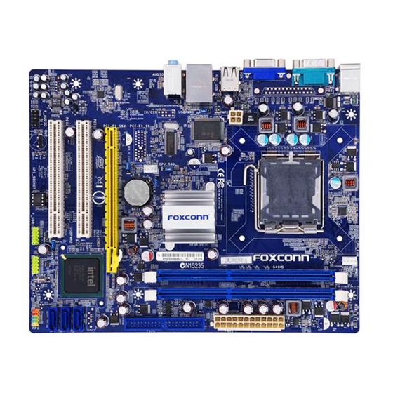
Page 11: Layout
1-2 Layout 12. South Bridge: Intel ® ICH7 1. 4-pin ATX 12V Power Connector 2. USBPWR1 Jumper 13. Front Panel Connector 3. CPU_533 Jumper 14. SATA Connectors 4. SYS_FAN Header 15. IDE Connector 5. MEM_OC_1333 Jumper 16. 24-pin ATX Power Connector 6. -
Page 12: Back Panel Connectors
1-3 Back Panel Connectors PS/2 Mouse Port LAN Port Line In Line Out Microphone In PS/2 Keyboard Port Serial Port VGA Port USB Ports Audio Ports 1. PS/2 Mouse Port Use the upper port (green) to connect a PS/2 mouse. 2. - Page 13 Left: Active Right: Link Link Active LAN Type Status Description Status Description No Link No Link 10 Mb/s Connection 1000M Green Data Green 100 Mb/s Connection Blinking Activity Orange 1000 Mb/s Connection...
- Page 14 This chapter introduces the hardware installation process, including the installation of the CPU, memory, power supply, slots, pin headers and the mounting of jumpers. Caution should be exercised during the installation of these modules. Please refer to the motherboard layout prior to any installation and read the contents in this chapter carefully.
-
Page 15: Install The Cpu And Cpu Cooler
2-1 Install the CPU and CPU Cooler Read the following guidelines before you begin to install the CPU : ■ Make sure that the motherboard supports the CPU. ■ Always turn off the computer and unplug the power cord from the power supply before installing the CPU to prevent hardware damage. - Page 16 Follow the steps to install the CPU onto the CPU socket : Before installing the CPU, make sure to turn off the computer and unplug the power cord from the power outlet to prevent damage to the CPU. 1. Remove protective socket cover. Remove protective socket cover.
-
Page 17: Install The Cpu Cooler
Install the CPU Cooler Follow the steps below to correctly install the CPU cooler on the motherboard. (The following procedures use Foxconn cooler as the example.) 1. Apply and spread an even thermal 2. Place the four bolts of the CPU grease on the surface of CPU. -
Page 18: Install The Memory
2-2 Install the Memory Read the following guidelines before you begin to install the memory : ■ Make sure that the motherboard supports the memory. It is recommended that memory of the same capacity, brand, speed, and chips be used. ■... -
Page 19: Installing A Memory
Installing a Memory Before installing a memory module, make sure to turn off the computer and unplug the power cord from the power outlet to prevent damage to the memory module. Be sure to install DDR3 DIMMs on this motherboard. Notch If you take a look at front side of memory module, it has asymmetric pin counts on both sides separated by a notch in the middle, so it can only fit in one direction. -
Page 20: Install An Expansion Card
2-3 Install an Expansion Card ■ Make sure the motherboard supports the expansion card. Carefully read the manual that came with your expansion card. ■ Always turn off the computer and unplug the power cord from the power outlet before installing an expansion card to prevent hardware damage. -
Page 21: Install Other Internal Connectors
2-4 Install other Internal Connectors Power Connectors This motherboard uses an ATX power supply. In order not to damage any device, make sure all the devices have been installed properly before applying the power supply. 24-pin ATX Power Connector : PWR1 PWR1 is the ATX power supply connector. - Page 22 Audio Connector : F_AUDIO PORT1_L AUD_GND The audio connector supports HD Audio standard. It PORT1_R PRESENCEJ provides the Front Audio output choice. PORT2_R SENSE1_RETURN SENSE_SEND EMPTY PORT2_L SENSE2_RETURN F_AUDIO SPKJ Speaker Connector : SPEAKER EMPTY The speaker connector is used to connect speaker SPKJ of the chassis.
- Page 23 Front Panel Connector : FP1 This motherboard includes one connector for connecting the front panel switch and LED Indicators. HDD-LED PWR-LED Hard Disk LED Connector (HDD-LED) RESET-SW PWR-SW Connect to the chassis front panel IDE indicator LED. EMPTY It indicates the active status of the hard disks. This 2-pin connector is directional with +/- sign.
-
Page 24: Jumpers
2-5 Jumpers For some features needed, users can change the jumper settings on this motherboard to modify them. This section explains how to use the various functions of this motherboard by changing the jumper settings. Users should read the following content carefully prior to modifying any jumper setting. Description of Jumpers 1. - Page 25 USB device wake-up Jumper: USBPWR1 / USBPWR2 1. Set the jumper to pins 1-2 (+5V) to wake up the computer from S1 sleep mode using the connected USB devices. 2. Set the jumper to pins 2-3 (+5VSB) to wake up the computer from S3 and S4 sleep modes using the connected USB devices.
- Page 26 Over Memory Frequency Jumper: MEM_OC_1333 When you use the memory which supports 1333/1066, the jumper is used to overclock memory frequency. and make the memory word at 1333MHz. Set the jumper to pins 2-3 (as Status 1) , memory frequency will be 1066MHz. This is default status.
-
Page 27: Install Driver And Utility
Manual Instal- lation Step by Step Automatic Installation by One Click. Exit the program Click to visit Select Select Browse CD Drop to Foxconn's to Install to Install System Tray website Utilities Drivers Choose the items you want to Install... - Page 28 2. Utility Use these options to install additional software programs.
- Page 29 This chapter tells how to change system settings through the BIOS Setup menus. Detailed descriptions of the BIOS parameters are also provided. You have to run the Setup Program when the following cases occur : 1. An error message appears on the screen during the system Power On Self Test (POST) process.
-
Page 30: Enter Bios Setup
Enter BIOS Setup The BIOS is the communication bridge between hardware and software, correctly setting up the BIOS parameters is critical to maintain optimal system performance. Power on the computer, when the message "Press <Del> to enter Setup, <Esc> to boot menu" appears at the bottom of the screen, you can press <DEL>... - Page 31 ► Power Management Setup All the items related with Green function features can be setup through this menu. ► PC Health Status This setup enables you to read/change fan speeds, and displays temperatures and voltages of your CPU/System. ► BIOS Security Features The Supervisor/User password can be set up through this menu to prevent unauthorized use of your computer.
-
Page 32: System Information
[All Errors But ...] �eyboard �eyboard [Disabled] [Disabled] Mouse Mouse [Disabled] [Disabled] Model Name :G41MD BIOS Version :A81F1D04 Memory :512MB MAC Address :90-FB-A6-30-0D-91 Intel (R) Core (TM) 2 Quad CPU Q9300 @ 2.5GHz ↑↓←→:Move Enter:Select +/-/:Value F10:Save ESC:Exit F1:General Help F9:Optimized Defaults ►... - Page 33 Model name of this product. ► BIOS Version It displays the current BIOS version. User can check this information and discuss with the field service people if a BIOS upgrade is needed. ► Memory This item shows the information of the system memory, determined by POST(Power On Self Test) of the BIOS.
-
Page 34: Advanced Bios Features
Advanced BIOS Features CMOS Setup Utility - Copyright (C) 1985-2008, American Megatrends, Inc. Advanced BIOS Features MPS Revision MPS Revision [1.4] [1.4] Help Item Help Item [1.4] PCI Latency Timer [64] Quiet Boot [Enabled] Select MPS Quick Boot [Enabled] Revision . Bootup Num-Lock [On] ↑↓←→:Move Enter:Select... - Page 35 ► Quick Boot While Enabled, this option allows BIOS to skip certain tests while booting, this will shorten the time needed to boot the system. ► Bootup Num-Lock This item defines if the keyboard Num Lock key is active when your system is started. The available settings are: On (default) and Off.
-
Page 36: Fox Central Control Unit Fox Central Control Unit
Fox Central Control Unit CMOS Setup Utility - Copyright (C) 1985-2008, American Megatrends, Inc. Fox Central Control Unit [Press Enter] ► Smart BIOS [Press Enter] Help Item ► CPU Configuration [Press Enter] ► Voltage Options [Press Enter] Spread Spectrum [Enabled] Auto Detect PCI CL�... -
Page 37: Smart Bios
Smart BIOS CMOS Setup Utility - Copyright (C) 1985-2008, American Megatrends, Inc. Smart BIOS Smart Power LED [Enabled] [Enabled] Help Item Smart Boot Menu [Enabled] Options Current CPU Speed : 2.50GHz Current FSB Speed : 1333MHz Current CPU Multiplier : 7.5 Disabled Current DRAM Speed : 800MHz... -
Page 38: Cpu Configuration
CPU Configuration CMOS Setup Utility - Copyright (C) 1985-2008, American Megatrends, Inc. CPU Configuration CPU Configuration Help Item Module Version : 3F.0F This should be enabled Manufacturer : Intel in order to enables or Intel(R) Core(TM)2 Quad CPU Q9300 @ 2.50GHz disable the “Enhanced Frequency :2.50GHz... - Page 39 Enhanced Intel SpeedStep ® technology (EIST) allows the system to dynamically adjust processor voltage and core frequency, which can result in decreased average power consumption and decreased average heat production. There are some system requirements must be met, including CPU, chipset, motherboard, BIOS and operation system.
-
Page 40: Advanced Chipset Features Advanced Chipset Features
Advanced Chipset Features CMOS Setup Utility - Copyright (C) 1985-2008, American Megatrends, Inc. Advanced Chipset Features Advanced Chipset Settings Help Item WARNING: Setting wrong values in below sections Configure North Bridge may cause system to malfunction. features. ► North Bridge Configuration ►... - Page 41 the time the memory controller srart sending commands to memory bank. The lower the value, the sonner the memory controller can send commands out to the activated memory bank. Op- tions are Auto, 1T and 2T. mode. ► Memory Timing by SPD This item is used to enable/disable provision of DRAM timing by SPD device.
-
Page 42: South Bridge Configuration
South Bridge Configuration CMOS Setup Utility - Copyright (C) 1985-2008, American Megatrends, Inc. South Bridge Configuration South Bridge Chipset Configuration South Bridge Chipset Configuration Help Item Options SMBUS Controller SMBUS Controller [Enabled] [Enabled] [Enabled] SLP_S4# Min. Assertion Width [1 to 2 seconds] Enabled Disabled ASPM... -
Page 43: Integrated Peripherals
Integrated Peripherals CMOS Setup Utility - Copyright (C) 1985-2008, American Megatrends, Inc. Integrated Peripherals ► IDE Configuration ► IDE Configuration [Press Enter] [Press Enter] Help Item ► OnBoard Configuration ► OnBoard Configuration [Press Enter] ► SuperIO Configuration ► SuperIO Configuration [Press Enter] Configure the IDE ►... - Page 44 OnBoard Configuration CMOS Setup Utility - Copyright (C) 1985-2008, American Megatrends, Inc. OnBoard Configuration OnBoard Configuration OnBoard Configuration Help Item Help Item Options OnBoard Audio Controller [Enabled] [Enabled] OnBoard LAN Controller [Enabled] OnBoard LAN Boot ROM OnBoard LAN Boot ROM [Disabled] Enabled Enabled...
-
Page 45: Superio Configuration
SuperIO Configuration CMOS Setup Utility - Copyright (C) 1985-2008, American Megatrends, Inc. SuperIO Configuration SuperIO Configuration SuperIO Configuration Help Item Help Item Serial Port1 Address [3F8/IRQ4] Allows BIOS to Select [3F8/IRQ4] Serial Port1 Mode [Normal] Serial Port1 Base Addresses . Addresses . -
Page 46: Usb Configuration
USB Configuration CMOS Setup Utility - Copyright (C) 1985-2008, American Megatrends, Inc. USB Configuration USB Configuration Help Item Module Version - 2.24.3-13.4 Enables support for legacy USB. AUTO AUTO USB Devices Enabled : option disables None legacy support if no USB devices are Legacy USB Support [Enabled] connected. -
Page 47: Power Management Setup
Power Management Setup CMOS Setup Utility - Copyright (C) 1985-2008, American Megatrends, Inc. Power Management Setup ACPI Suspend Type [S3 (STR)] [S3 (STR)] Help Item Power On after Power Fail [Power Off] HPET [Enabled] Select the ACPI Resume by Ring [Enabled] state used for Resume by LAN... - Page 48 ► ACPI Suspend Type This item is used to set the energy saving mode of the ACPI function. When you select “S1 (POS)” mode, the power is always on and computer can be resumed at any time. When you select “S3 (STR)” mode, the power will be down after a period of time. The status of the computer before it entering STR will be saved in memory, and the computer can quickly return to previous state when the STR function wakes.
-
Page 49: Pc Health Status
PC Health Status CMOS Setup Utility - Copyright (C) 1985-2008, American Megatrends, Inc. PC Health Status [Disabled] Warning Temperature Help Item Shutdown Temperature [Disabled] Options Case Open Warning [Disabled] CPU Temperature C/84 System Temperature C/87 Disabled C/122 CPU Fan Speed :1991 RPM C/131 System Fan Speed... -
Page 50: Bios Security Features
BIOS Security Features CMOS Setup Utility - Copyright (C) 1985-2008, American Megatrends, Inc. BIOS Security Features Supervisor Password : Not Installed Help Item User Password : Not Installed Change Supervisor Password [Press Enter] Install or change the Change User Password Change User Password [Press Enter] password. -
Page 51: Load Optimal Defaults
Load Optimal Defaults Optimal defaults are the best settings of this motherboard. Always load the Optimal defaults after updating the BIOS or after clearing the Load Optimal Defaults? CMOS values. Select this option and press Enter, it will pop out a dialogue box to let [O�] [O�] [Cancel]...