SOYO SY-P4X400 DRAGON Ultra User Manual
P4x400 series motherboard mpga socket 478 processor supported via p4x400 agp pro/pci 400/533 mhz front side bus supported atx form factor
Hide thumbs
Also See for SY-P4X400 DRAGON Ultra:
- Quick start manual (31 pages) ,
- User manual (103 pages)
Table of Contents
Advertisement
Quick Links
Congratulations on your new purchase of SOYO P4X400 Series
motherboard for the Intel platform!
This new motherboard offers support for ultra fast DDR400 memory.
However, since DDR400 is not a JEDEC (The Joint Electron Device
Engineering Council) approved memory specification, some users might
experience DDR400 incompatibilities as a result of discrepancy in memory
manufacturing.
In an effort to provide our customers the highest product quality and
performance, SOYO has tested a number of memory modules to ensure
compatibility. Please visit our web site at
http://www.soyousa.com/products/proddesc.php?id=159
for information
on Recommended Memory.
In some cases BIOS upgrade might be required to take advantage of this
new feature. Please refer to our Support section on the web site for more
information.
Advertisement
Table of Contents

Related Manuals for SOYO SY-P4X400 DRAGON Ultra


Summary of Contents for SOYO SY-P4X400 DRAGON Ultra
- Page 1 DDR400 incompatibilities as a result of discrepancy in memory manufacturing. In an effort to provide our customers the highest product quality and performance, SOYO has tested a number of memory modules to ensure compatibility. Please visit our web site at http://www.soyousa.com/products/proddesc.php?id=159 for information on Recommended Memory.
- Page 2 SY-P4X400 DRAGON Ultra Motherboard **************************************************** mPGA Socket 478 Processor supported VIA P4X400 AGP PRO/PCI 400/533 MHz Front Side Bus supported ATX Form Factor **************************************************** User's Manual...
- Page 3 It is the policy of SOYO Computer Inc. to respect the valid patent rights of third parties and not to infringe upon or to cause others to infringe upon such rights.
-
Page 4: Table Of Contents
CHAPTER 1 MOTHERBOARD DESCRIPTION......1 INTRODUCTION.............1 UNPACKING THE MOTHERBOARD ......1 KEY FEATURES..............2 HANDLING THE MOTHERBOARD ......6 ELECTROSTATIC DISCHARGE PRECAUTIONS..6 ....7 SY-P4X400 DRAGON Ultra MOTHERBOARD LAYOUT ..8 SY-P4X400 DRAGON Ultra MOTHERBOARD COMPONENTS CHAPTER 2 HARDWARE INSTALLATION ........10 PREPARATIONS............10 INSTALLATION GUIDE ..........11 QUICK BIOS SETUP.............34 CHAPTER 3 BIOS SETUP UTILITY..........36... - Page 5 Table of Contents SY-P4X400 DRAGON Ultra CAHPTER 7 REALTEK LAN DRIVER INSTALLATION.....94 APPENDIX A HIGHPOINT HPT372 MANUAL .......95 APPENDIX B ..127 C-MEDIA 6 CHANNEL AUDIO SOLUTION MANUAL APPENDIX C TROUBLE SHOOTING AT FIRST START ....166 APPENDIX D CONTACT INFORMATION........173...
-
Page 6: Chapter 1 Motherboard Description
The SY-P4X400 DRAGON Ultra AGP PRO/PCI Motherboard is a high-performance Socket 478 processor supported ATX form-factor system board. The SY-P4X400 DRAGON Ultra uses VIA Chipset technology and supports Socket 478 class processors. This Motherboard is fully compatible with industry standards and adds many technical enhancements. -
Page 7: Key Features
Pentium® 4 Northwood or Willamette (400MHz /533MHz FSB) Pentium® 4 Celeron CPU SETTINGS The SY-P4X400 DRAGON Ultra provides the user with a very complete and convenient CPU setting environment. The CPU settings are all adjusted through the special SOYO COMBO page in the BIOS, therefore rendering the use of jumpers obsolete. -
Page 8: Memory Support
Motherboard Description SY-P4X400 DRAGON Ultra This ensures that the SY-P4X400 DRAGON Ultra has an overwhelming overclocking potential. CPU Multiplier The SY-P4X400 DRAGON Ultra supports a wide range of multipliers: 10X ~ 24X depend on CPU. MEMORY SUPPORT The SY-P4X400 DRAGON Ultra supports PC1600, PC2100 and PC2700 DDR Memory module. -
Page 9: Hardware Monitor
CD-ROM, LS-120, etc. Power on by modem or alarm If the SY-P4X400 DRAGON Ultra system is in suspend mode, it can be switched back on through the modem or RTC alarm through this function. This opens a lot of possibilities, such as remote access that switches the system on only after the modem receives a call. - Page 10 SOYO Bonus Pack CD-ROM COMPLIANCE The SY-P4X400 DRAGON Ultra complies with all important industry standards. The following underlines the reliability of the SY-P4X400 DRAGON Ultra, a motherboard to trust.
-
Page 11: Handling The Motherboard
Motherboard Description SY-P4X400 DRAGON Ultra 1-4 HANDLING THE MOTHERBOARD To avoid damage to your Motherboard, follow these simple rules while unpacking: Before handling the Motherboard, ground yourself by grasping an unpainted portion of the system's metal chassis. Remove the Motherboard from its anti-static packaging. Hold the Motherboard by the edges and avoid touching its components. -
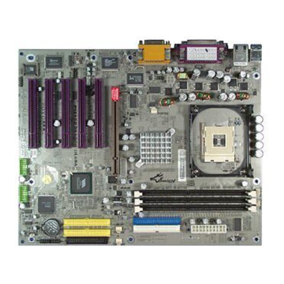
Page 12: Sy-P4X400 Dragon Ultra Motherboard Layout
Motherboard Description SY-P4X400 DRAGON Ultra 1-6 SY-P4X400 DRAGON Ultra MOTHERBOARD LAYOUT PS/2 KB PS/2 Mouse PS/2 Mouse Connector Connector USB 1_2 ATX Power COM A COM B AOUT □ P4X400 AMIC IDE 1 IDE 2 AGAME REALTEK RTL8100B Peripheral Power... -
Page 13: Sy-P4X400 Dragon Ultra Motherboard Components
Motherboard Description SY-P4X400 DRAGON Ultra 1-7 SY-P4X400 DRAGON Ultra MOTHERBOARD COMPONENTS A B C... - Page 14 Motherboard Description SY-P4X400 DRAGON Ultra +12V Power Connector Front panel Connectors Chassis Cooling Fan Connector Socket 478 Connector VIA P4X400 North Bridge Chip Peripheral Power Connector CPU Cooling Fan Connector DIMM Banks ATX Power Supply Connector Bus Mastering EIDE/ATAPI Ports...
-
Page 15: Chapter 2 Hardware Installation
SY-P4X400 DRAGON Ultra Chapter 2 HARDWARE INSTALLATION Congratulations on your purchase of SY-P4X400 DRAGON Ultra Motherboard. You are about to install and connect your new Motherboard. Note: Do not unpack the Motherboard from its protective anti-static packaging until you have made the following preparations. -
Page 16: Installation Guide
Hardware Installation SY-P4X400 DRAGON Ultra 2-2 INSTALLATION GUIDE We will now begin the installation of the Motherboard. Please follow the step-by-step procedure designed to lead you to a complete and correct installation. Step 1- Install the Central Processing Unit (CPU) -
Page 17: Step 1 Install The Cpu
Hardware Installation SY-P4X400 DRAGON Ultra STEP 1 Install the CPU ® CPU Mount Procedure: To mount the Pentium 4 Socket mPGA478 processor that you have purchased separately, follow these instructions. Lift the socket handle up to a vertical position. Align the blunt edge of the CPU with the matching pinhole distinctive... -
Page 18: Cpu Fan Installation
Hardware Installation SY-P4X400 DRAGON Ultra Seat the processor in the socket completely and without forcing. Then close the socket handle to secure the CPU in place. Remember to connect the CPU Cooling Fan to the appropriate power connector on the Motherboard. The fan is a key component that will ensure system stability. -
Page 19: Step 2 Install Memory Module
Hardware Installation SY-P4X400 DRAGON Ultra Step 2 Install Memory Module □ Your board comes with three DIMM sockets, Directly supports one DDR SDRAM channel, 64b wide, providing support max of 3 Double-Sided DIMMs with unbuffered DDR 266. The largest memory capacity possible is 3GB. -
Page 20: Memory Configuration Table
Hardware Installation SY-P4X400 DRAGON Ultra Memory Configuration Table Number of Memory DIMM 1 DIMM 2 DIMM 3 Modules DDR SDRAM (Un-buffered and RAM Type Non-ECC) Memory Module Size (MB) 64/128/256/512 MB/1 GB Step 3 Install Expansion Card The motherboard has 1 AGP PRO and 5 PCI slot. - Page 21 Hardware Installation SY-P4X400 DRAGON Ultra AGP Pro Slot This motherboard supports AGP 2x/4x/8x Pro VGA CARD. DO NOT remove the safety tab underneath it if you will be using an AGP card without a retention notch. Removing may cause the card to shift and may cause damage to your card, slot, and motherboard.
- Page 22 Hardware Installation SY-P4X400 DRAGON Ultra Step 4 Connect cables, case wires, and power supply A. IDE Device Installation (HDD, CD-ROM) □ Pin -1 IDE 1 IDE 2 Primary Secondary This Motherboard offers two primary and secondary IDE device connectors (IDE1, IDE2). It can support up to four high-speed Ultra DMA 33/ 66/100/133 HDD or CD-ROM.
- Page 23 Hardware Installation SY-P4X400 DRAGON Ultra B. Floppy Drive Installation Pin-1 □ Floppy Drive connector The system supports 5 possible floppy drive types: 720 KB, 1.2 MB, 1.44 MB, 2.88 MB, and LS-120. Connect one side of the 34-pin flat cable to the floppy drive and plug the other end to the floppy drive connector on the Motherboard.
- Page 24 Hardware Installation SY-P4X400 DRAGON Ultra Front Panel Connections HDD LED Speaker ACPI LED □ Key Lock PWRBT Power LED Reset Plug the computer case's front panel devices to the corresponding headers on the Motherboard. 1. Power LED & KeyLock Plug the Power LED cable into the 5-pin Keylock header.
- Page 25 Hardware Installation SY-P4X400 DRAGON Ultra 2. Reset Plug the Reset push-button cable into the 2-pin Reset header on the Motherboard. Pushing the Reset button on the front panel will cause the system to restart the boot-up sequence. Reset Pin Assignment Power Good 3.
- Page 26 Hardware Installation SY-P4X400 DRAGON Ultra 5. ATX Power On/Off Switch Attach the 2-pin momentary type switch to the PWRBT header for turning On or Off your ATX power supply. PWRBT Pin Assignment Power On/Off D. Back Panel Connections All external devices such as the PS/2 keyboard, PS/2 mouse, printer, modem, USB can be plugged directly onto the Motherboard back panel.
- Page 27 Hardware Installation SY-P4X400 DRAGON Ultra 1. Onboard Serial Ports COMA/COMB External peripherals that use serial transmission scheme include: serial mouse, and modem. Plug the serial device cables directly into the COMA/COMB 9-pin male connectors located at the rear panel of the Motherboard.
- Page 28 Hardware Installation SY-P4X400 DRAGON Ultra 5. Universal Serial Bus (USB1/USB2, USB20_1/USB20_2) This Motherboard provides four USB ports for your additional devices. Plug the USB device jack into the available USB connector USB1 or USB2. Standard device drivers come with the Win98 for commonly used USB devices.
- Page 29 Hardware Installation SY-P4X400 DRAGON Ultra E. Other Connections 1. Wake-On-LAN (WOL) Attach the 3-pin connector from the LAN card which supports the Wake-On-LAN (WOL) function to the JP10 header on the Motherboard. This WOL function lets users wake up the connected computer through the LAN card.
- Page 30 Hardware Installation SY-P4X400 DRAGON Ultra 2. Standard Infrared (SIRCON) Plug the 10-pin infrared device cable to the SIRCON header. This will enable the infrared transfer function. This Motherboard meets both the ASKIR and HPSIR specifications. Please install according to the following pin assignment:...
- Page 31 Hardware Installation SY-P4X400 DRAGON Ultra 3. Cooling Fan Installation (1) CPU Cooling Fan (CPUFAN1, CPUFAN2) After you have seated the CPU properly on the processor, attach the 3-pin fan cable to the CPUFAN connector on the Motherboard. The fan will stop when the system enters into Suspend Mode.
- Page 32 Hardware Installation SY-P4X400 DRAGON Ultra (2) Chassis Cooling Fan (CHAFAN1, CHAFAN2, CHAFAN3) Some chassis also feature a cooling fan. This Motherboard features a CHAFAN connector to provide 12V power to the chassis fan. Connect the cable from the chassis fan to the CHAFAN 3-pin connector. Install...
- Page 33 Hardware Installation SY-P4X400 DRAGON Ultra 4. CD Line-in (CDIN1,CDIN2) This Motherboard provides one CD-Line in connectors. Please connect the 4-pin audio cable from your CD-ROM drive to either CDIN2. (It fits in only one, depending on the cable that came with your CD-ROM drive)
- Page 34 Hardware Installation SY-P4X400 DRAGON Ultra 5. SPK5(optional) Connect one end of the Audio flat cable to SPK5 connector in the motherboard, and the other end to the small audio connector. (See unpacking the motherboard in Chapter 1 for more info on the audio flat...
- Page 35 Hardware Installation SY-P4X400 DRAGON Ultra 6. MIC & LED Connector (J30) You can connect the Line-out /MIC in/LAN LED to the front panel of your PC case. (If this option is available in your PC case.)
-
Page 36: Atx Power
Hardware Installation SY-P4X400 DRAGON Ultra F. ATX Power Supply Use power supply specifically for P4 M/B. (ATX 12V power supply) The ATX12V power supply includes a 20-pin ATX connector that comply with the ATX specification, Version 2.03 for M/B specification, a new 4-pin receptacle/header combination--the +12V power connector--has been defined. - Page 37 Hardware Installation SY-P4X400 DRAGON Ultra Warning: Follow these precautions to preserve your Motherboard from any remnant currents when connecting to ATX power supply: Turn off the power supply and unplug the power cord of the ATX power supply before connecting to ATX PW connector.
-
Page 38: Step 5 Power On
Hardware Installation SY-P4X400 DRAGON Ultra G. CMOS Clear (JP5) In some cases the CMOS memory may contain wrong data, follow the steps below to clear the CMOS memory. Clear the CMOS memory by momentarily shorting pin 2-3 on jumper JP5. This jumper can be easily identified by its white colored cap. -
Page 39: Quick Bios Setup
This Motherboard does not use any hardware jumpers to set the CPU frequency. Instead, CPU settings are software configurable with the BIOS [SOYO COMBO FEATURE]. The [SOYO COMBO FEATURE] combines the main parameters that you need to configure, all in one menu, for a quick setup in BIOS. - Page 40 Step 2. Select [LOAD OPTIMIZED DEFAULTS] Select the “LOAD OPTIMIZED DEFAULTS” menu and type “Y” at the prompt to load the BIOS optimal setup. Step 3. Select [SOYO COMBO FEATURE] Move the cursor to the [CPU Frequency Select], [CPU Ratio] field to set CPU Clock/Ratio.
-
Page 41: Chapter 3 Bios Setup Utility
BIOS Setup Utility SY-P4X400 DRAGON Ultra Chapter 3 BIOS SETUP UTILITY This Motherboard's BIOS setup program uses the ROM PCI BIOS program from Award Software Inc. To enter the Award BIOS program's Main Menu: 1. Turn on or reboot the system. - Page 42 BIOS Setup Utility SY-P4X400 DRAGON Ultra Hot Keys: Function keys give you access to a group of commands throughout the BIOS utility. Function Command Description Gives the list of options available for each General Help item. Previous Restore the old values. These are the values Values that the user started the current session with.
-
Page 43: Save And Exit Setup
BIOS Setup Utility SY-P4X400 DRAGON Ultra SAVE AND EXIT SETUP Select the [SAVE & EXIT SETUP] option from the Main Menu to save data to CMOS and exit the setup utility. This option saves all your changes and causes the system to reboot. -
Page 44: Soyo Combo Setup
<DEL> key during the system diagnostic checks to enter the Award BIOS Setup program. The CMOS SETUP UTILITY will display on screen. Then, select the [SOYO COMBO SETUP] option from the main menu and press the <Enter> key. -
Page 45: Soyo Combo Feature
BIOS Setup Utility SY-P4X400 DRAGON Ultra System Performance Setting Description Note System Normal Adjust your computer Default Performance performance. Fast Turbo SOYO COMBO Feature Setting Description Note Frequency 100 MHz Press “Page Up” / “Page Down” key to 1MHz Stepping... -
Page 46: Onboard Ide Raid
BIOS Setup Utility SY-P4X400 DRAGON Ultra CPU Vcore Select Setting Description Note CPU Vcore Default This function adjust the CPU Default 1.100V, 1.125V, Select voltage. 1.150V, 1.175V, 1.200V, 1.225V, 1.250V, 1.275V, 1.300V, 1.325V, 1.350V, 1.375V, 1.400V, 1.425V, 1.450V, 1.475V, 1.500V, 1.525V, 1.550V, 1.575V,... - Page 47 BIOS Setup Utility SY-P4X400 DRAGON Ultra Onboard 6Ch H/W Audio Setting Description Note Onboard 6Ch Enabled Enabled/Disabled Onboard 6Ch Default H/W Audio H/W Audio. Disabled Onboard (10/100) LAN Setting Description Note Enabled Enabled/Disabled Onboard LAN. Default Onboard (10/100) LAN Disabled...
-
Page 48: System Boot Control Settings
BIOS Setup Utility SY-P4X400 DRAGON Ultra System Boot Control Settings Setting Description Note First Select Your Boot Floppy /Second/Third Device Priority LS120 Boot Device HDD-0 SCSI CDROM HDD-1 HDD-2 HDD-3 ZIP100 USB-FDD USB-ZIP USB-CDROM USB-HDD Disabled Boot Other Disabled Select Your Boot... - Page 49 BIOS Setup Utility SY-P4X400 DRAGON Ultra 3-1.1 Advance Turn-up Settings Caution: Change these settings only if you are already familiar with the Chipset. The [Advanced Turn-up Settings] option changes the values of the chipset registers. These registers control the system options in the computer.
- Page 50 BIOS Setup Utility SY-P4X400 DRAGON Ultra DRAM Timing/Drive Control Setting Description Note DRAM Timing By SPD Default If enable the DRAM will auto detect the DRAM timing. Manual Default SDRAM CAS When synchronous DRAM is installed, the number of clock...
-
Page 51: Standard Cmos Setup
BIOS Setup Utility SY-P4X400 DRAGON Ultra 3-2 STANDARD CMOS SETUP Select the [STANDARD CMOS SETUP] option from the Main Menu and press [Enter] key. CMOS Setup Utility – Copyright ( C ) 1984-2002 Award Software Standard CMOS Features Date (mm:dd:yy) - Page 52 BIOS Setup Utility SY-P4X400 DRAGON Ultra This Main Menu function automatically detects the hard disk type and configures the [Standard CMOS Features] accordingly. CMOS Setup Utility – Copyright ( C ) 1984-2002 Award Software IDE Primary Master IDE HDD Auto-Detection...
-
Page 53: Floppy Drives
BIOS Setup Utility SY-P4X400 DRAGON Ultra Hard Disks Type & Mode Choose the type and mode for the hard disks that you have already installed. Primary Setting Description Note (Secondary) Master & Slave IDE HDD Press To auto-detect the HDD’s size,... - Page 54 BIOS Setup Utility SY-P4X400 DRAGON Ultra Others Optional Setting Description Note EGA/VGA Select the video mode. Default Video CGA 40 CGA 80 MONO (Monochrome) ALL Errors When the BIOS detects system Default Halt On errors, this function will stop the No Errors system.
-
Page 55: Advanced Bios Features
BIOS Setup Utility SY-P4X400 DRAGON Ultra 3-3 ADVANCED BIOS FEATURES Select the [Advanced BIOS Features] option from the Main Menu and press [Enter] key. CMOS Setup Utility – Copyright ( C ) 1984-2002 Award Software Advanced BIOS Features Virus Warning... -
Page 56: Boot Up Floppy Seek
BIOS Setup Utility SY-P4X400 DRAGON Ultra Cache Memory Options Setting Description Note CPU L1 & L2 Cache Disabled Enabled Enables the CPU's L1 & Default L2 cache. Disabled Default Swap Floppy Drive Enabled Boot Up Floppy Seek Setting Description Note... -
Page 57: Security Option
BIOS Setup Utility SY-P4X400 DRAGON Ultra Typematic Settings Typematic Settings Setting Description Note Typematic Disabled Keystrokes repeat at a rate Default determined by the Rate Setting keyboard. Enabled When enabled, the typematic rate and typematic delay can be selected. The following [Typematic Rate] and [Typematic Delay] fields are active... - Page 58 Disabled Set Enabled to Show Logo (Dragon). LOGO Show Enabled Default EPA LOGO LOGO-0 Default Allows user to display SOYO logo or SELECT LOGO-1 own logo.Logo-0 Shows SOYO logo. Logo-1 Shows user logo (Default Blank). Small Disabled Set Enabled to Show Logo(EPA).
-
Page 59: Advanced Chipset Features
BIOS Setup Utility SY-P4X400 DRAGON Ultra 3-4 ADVANCED CHIPSET FEATURES Select the [Advanced Chipset Features] option from the Main Menu and press [Enter] key. Caution: Change these settings only if you are already familiar with the Chipset. The [Advanced Chipset Features] option changes the values of the chipset registers. - Page 60 BIOS Setup Utility SY-P4X400 DRAGON Ultra 3-4.1 AGP & P2P Bridge Control Caution: Change these settings only if you are already familiar with the Chipset. The [AGP & P2P Bridge Control] option changes the values of the chipset registers. These registers control the system options in the computer.
- Page 61 BIOS Setup Utility SY-P4X400 DRAGON Ultra AGP & P2P Bridge Control (Continue) Setting Description Note AGP Driving Auto This item allows you to adjust the AGP Default driving force. Choose Manual to key in Control Manual a AGP Driving Value in the next selection.
- Page 62 BIOS Setup Utility SY-P4X400 DRAGON Ultra 3-4.2 CPU & PCI Bus Control Caution: Change these settings only if you are already familiar with the Chipset. The [CPU & PCI Bus Control] option changes the values of the chipset registers. These registers control the system options in the computer.
-
Page 63: Integrated Peripherals
BIOS Setup Utility SY-P4X400 DRAGON Ultra 3-5 INTEGRATED PERIPHERALS Select the [Integrated Peripherals] option from the Main Menu and press [Enter] key. Caution: Change these settings only if you are already familiar with the Chipset. The [INTEGRATED PERIPHERALS] option changes the values of the chipset registers. - Page 64 BIOS Setup Utility SY-P4X400 DRAGON Ultra INTEGRATED PERIPHERALS (Continue) Setting Description Note All Disabled This should be enabled if OnChip USB Controller your system has a USB All Enabled Default installed on the system board and you want to use it.
-
Page 65: Via Onchip Ide Device
BIOS Setup Utility SY-P4X400 DRAGON Ultra 3-5.1 VIA OnChip IDE Device Caution: Change these settings only if you are already familiar with the Chipset. The [VIA OnChip IDE Device] option changes the values of the chipset registers. These registers control the system options in the computer. - Page 66 BIOS Setup Utility SY-P4X400 DRAGON Ultra VIA OnChip IDE Device Setting Description Note Disabled Turn off the on-board IDE. On-Chip PCI IDE Primary Enabled Use the on-board IDE. Default Secondary mode 0-4 0 is the slowest speed Primary Master PIO...
-
Page 67: Superio Device
BIOS Setup Utility SY-P4X400 DRAGON Ultra 3-5.2 SuperIO Device Caution: Change these settings only if you are already familiar with the Chipset. The [SuperIO Device] option changes the values of the chipset registers. These registers control the system options in the computer. - Page 68 BIOS Setup Utility SY-P4X400 DRAGON Ultra SuperIO Device Setting Description Note Onboard FDC Disabled Turn off the on-board floppy controller controller. Enabled Use the on-board floppy controller. Default Onboard Disabled Serial Port 1 / 3F8/IRQ4 Choose serial port 1 & 2's I/O...
-
Page 69: Power Management Setup
BIOS Setup Utility SY-P4X400 DRAGON Ultra 3-6 POWER MANAGEMENT SETUP The [POWER MANAGEMENT SETUP] sets the system's power saving functions. CMOS Setup Utility – Copyright ( C ) 1984-2002 Award Software Power Management Setup ACPI Suspend Type S1 (POS) Item Help... - Page 70 BIOS Setup Utility SY-P4X400 DRAGON Ultra Power Management Controls Setting Description Note ACPI Suspend S1(POS) The system will enter the S1 Default Type state during suspend. (Low S3(STR) latency wake up) S1 & S3 Power User Define Lets you define the system...
- Page 71 BIOS Setup Utility SY-P4X400 DRAGON Ultra Power Management Controls (Continue) Setting Description Note MODEM Use Assigns an IRQ# to the modem Default device. 4-11, NA Soft-Off by Delay 4 Sec. Turns off the system power 4 PWR-BTTN seconds after pushing the power button.
- Page 72 BIOS Setup Utility SY-P4X400 DRAGON Ultra IRQ/Event Activity Detect Setting Description Note PS2KB Hot key You can boot-up your system by PS/2 Default Wakeup Select Password K/B VIA hotkey or password. You can set the following hotkey : PS2KB Disabled Default 1.
-
Page 73: Irqs Activity Monitoring
BIOS Setup Utility SY-P4X400 DRAGON Ultra 3-6.1 IRQs Activity Monitoring This option sets the IRQs Activity Monitoring. CMOS Setup Utility – Copyright ( C ) 1984-2002 Award Software IRQs Activity Monitoring Primary INTR Item Help IRQ3 (COM 2) Disabled IRQ4 (COM 1) -
Page 74: Pnp/Pci Configurations
BIOS Setup Utility SY-P4X400 DRAGON Ultra 3-7 PNP/PCI CONFIGURATIONS This option sets the Motherboard’s PCI Slots. CMOS Setup Utility – Copyright ( C ) 1984-2002 Award Software PNP/PCI Configurations PNP OS Installed Item Help Reset Configuration Data Disabled Menu Level... -
Page 75: Pnp/Pci Configuration Controls
BIOS Setup Utility SY-P4X400 DRAGON Ultra PNP/PCI Configuration Controls PNP/PCI Setting Description Note Controls PNP OS Set this field to [Yes] if you Installed are running Windows 95, which is PnP compatible. If the OS you are running Default does not support PnP... - Page 76 BIOS Setup Utility SY-P4X400 DRAGON Ultra PNP/PCI Configuration Setup (Continue) PNP/PCI Setting Description Note Setup Interrupt How to set the BIOS to release the IRQ to the PnP Interrupt pool: Line PnP / PCI configuration Integrated Peripherals IRQ 15 IRQ 15: PCI / ISA PnP...
-
Page 77: Pc Health Status
BIOS Setup Utility SY-P4X400 DRAGON Ultra 3-8 PC HEALTH STATUS This option sets the Motherboard's PC Health Status. CMOS Setup Utility – Copyright ( C ) 1984-2002 Award Software PC Health Status Shutdown Temperature Disabled Item Help Vcore 1.77 V + 3.3 V... - Page 78 BIOS Setup Utility SY-P4X400 DRAGON Ultra CPU Device Monitoring (Continue) Setting Description Note Vcore, +3.3V, Show the current voltage status. +12V Show the current status of CPU °C/°F Temperature temperature. Show the current status of the °C/°F Temperature System temperature.
-
Page 79: Load Fail-Safe Defaults
BIOS Setup Utility SY-P4X400 DRAGON Ultra 3-9 LOAD FAIL-SAFE DEFAULTS Select the [Load Fail-Safe Defaults] option from the Main Menu to load a pre-defined safe bios settings. This option is recommended if you have instability issue. CMOS Setup Utility – Copyright ( C ) 1984-2002 Award Software... -
Page 80: Load Optimized Defaults
BIOS Setup Utility SY-P4X400 DRAGON Ultra 3-10 LOAD OPTIMIZED DEFAULTS Select the [Load Optimized Defaults] option from the Main Menu to load a pre-defined optimized BIOS settings. CMOS Setup Utility – Copyright ( C ) 1984-2002 Award Software SOYO COMBO Feature... -
Page 81: Set Supervisor Password
BIOS Setup Utility SY-P4X400 DRAGON Ultra 3-11 SET SUPERVISOR PASSWORD Based on the setting you have made in the [Security Option] of the [BIOS FEATURES SETUP] section, the password prevents access to the system or the setup program by unauthorized users. Follow this procedure to set a new... -
Page 82: Set User Password
BIOS Setup Utility SY-P4X400 DRAGON Ultra Enter your new password and press [Enter]. The following message appears, prompting to confirm the new password: Confirm Password: Re-enter your password and then press [Enter] to exit to the Main Menu. This diagram outlines the password selection procedure: Type the Password Press <Enter>... -
Page 83: Boot Menu
BIOS Setup Utility SY-P4X400 DRAGON Ultra BOOT MENU Boot Menu enables user to boot-up on different boot device without going into the BIOS setup. To enable boot Menu, press “ESC” after memory initialization, user will see a device menu, in which user can choose the device they wish to boot from. -
Page 84: Cahpter 4 Drivers Installation
Step 1. Insert the SOYO CD into the CD-ROM drive If you use Windows 2000, NT or XP, the SOYO-CD will not detect your motherboard type. In that case the following dialog will pop up, please choose your motherboard and press OK. - Page 85 Drivers Installation SY-P4X400 DRAGON Ultra The user's manual files included on the SOYO CD are in PDF (Postscript Document) format. In order to read a PDF file, the appropriate Acrobat Reader software must be installed in your system. Note: The Start Up program automatically detects if the Acrobat Reader utility is already present in your system, and otherwise prompts you on whether or not you want to install it.
- Page 86 Drivers Installation SY-P4X400 DRAGON Ultra Step 2. Install Drivers and Utilities The following drivers need to be installed in order for the system to operate properly 1. VIA 4 in 1 driver. 2. C-Media 8738 audio driver. – Only required if you are using the onboard audio.
- Page 87 Drivers Installation SY-P4X400 DRAGON Ultra and maintain the stability of systems using VIA chipsets. These four drivers are: VIA Registry (INF) Driver, VIA AGP VxD driver, VIA ATAPI Vendor Support Driver and VIA PCI IRQ Miniport Driver. For Windows NT users, the VIA IDE Bus Mastering driver is the only driver to be installed in your system.
- Page 88 Step 3. Check the Latest Releases Click the 'Check the latest Releases' button to go the SOYO Website to automatically find the latest BIOS, manual and driver releases for your motherboard. This button will only work if your computer is connected to the internet through a network or modem connection.
- Page 89 Drivers Installation SY-P4X400 DRAGON Ultra After Windows XP installation, your device manager should look like this:...
- Page 90 Drivers Installation SY-P4X400 DRAGON Ultra After driver installation, your Windows XP device manager should look like this:...
- Page 91 Drivers Installation SY-P4X400 DRAGON Ultra Drivers directory list in the CD driver...
-
Page 92: Cahpter 5 Audio Driver Installation
Double click control panel. Double click multimedia and select devices. Select ADD and select OK. Click on “Browse” then point it to the SOYO CD for the Audio driver. The audio driver path is in “d:\audio\cmi8738_6ch\Win_NT40\drv.” (where D: is your CD-ROM) -
Page 93: Cahpter 6 Highpoint Hpt372 Driver Installation
Highpoint HPT372 Driver Installation SY-P4X400 DRAGON Ultra Chapter 6 Highpoint HPT 372 Driver Installation You can use your HPT372 as Normal IDE function. RAID function. To use IDE3 and IDE4 as normal IDE, please do the following steps 1. Enable on-board IDE RAID in the bios. - Page 94 Driver item, then click button. 3. In the follow-on window, select Have Disk..4. Insert the SOYO CD of driver, input the path of driver D:\Raid\Hot372\WinNT, then click 5. In the follow-on window, select HPT370/HPT372 UDMA/ATA RAID Controller item, then click 6.
- Page 95 Highpoint HPT372 Driver Installation SY-P4X400 DRAGON Ultra 6. Insert SOYO Driver CD, click next 7. During installation, Win 2K will prompt you to insert the RAID driver diskette 8. Browse to the directory that contains the missing file (D:\raid\hpt372\winxp). 9. Follow the system prompt to finish the installation, and restart the computer.
- Page 96 Highpoint HPT372 Driver Installation SY-P4X400 DRAGON Ultra Installing Driver During OS Installation Install driver during Windows NT4.0 installation 1. Go to “d:\raid\hpt372\” directory, (assuming that your CD-ROM is drive d) copy all the files and directory to a floppy disk.
- Page 97 Highpoint HPT372 Driver Installation SY-P4X400 DRAGON Ultra Install driver during Windows 2000 installation 1. Go to “d:\raid\hpt372\” directory, (assuming that your CD-ROM is drive d) copy all the files and directory to a floppy disk. 2. If Windows 2000 is installed from the floppy drive, please let the installing program run automatically.
- Page 98 Highpoint HPT372 Driver Installation SY-P4X400 DRAGON Ultra Install driver during Windows XP installation 1. Go to “d:\raid\\hpt372\” directory, (assuming that your CD-ROM is drive d) copy all the files and directory to a floppy disk. 2. Booting from CD-ROM, when the...
- Page 99 Realtek Lan Driver Installation SY-P4X400 DRAGON Ultra Chapter 7 Realtek LAN Driver Installation Install the Realtek LAN Drivers under windows NT4.0 Double click the Network icon in the control panel. The Network properties windows will appear. Click on the Devices tab and press the Add button.
- Page 100 APPENDIX A HighPoint HPT 372...
-
Page 101: Getting Started
Introduction HPT372 is a UDMA/ATA133 RAID controller. You can either use HPT 372 (IDE3, IDE4) as a RAID controller or as a regular IDE controller. RAID Administrator is a Windows-based RAID management utility for HPT372 RAID Controller. With graphical user interface, RAID Administrator enable users to easily configure, manage harddisk and disk arrays connected to HPT372 RAID controller. - Page 102 To be able to use the RAID function, please do the following: 1. Connect the 2 Hard disk on IDE3/4 2. Enable the RAID function in the BIOS 3. Create a Disk Array. For create instructions see below. 4. Install HPT 372 driver; check chapter 6 for driver installation procedure.
-
Page 103: Enter Into Bios Configuration Utility
HPT372 BIOS Utility Configuration Enter into BIOS Configuration Utility When the following information is displayed on screen during the system start-up, press Ctrl+H key to enter into BIOS configuration utility. The main interface of BIOS configuration utility is as below: Menu: It displays all items of the operating command. - Page 104 4. Select the intended RAID level in the popup selection box and press Enter. 5. Select 2. Select Disk Drives in the menu and press Enter. 6. Select the harddisks to be used for creating the disk array and press Enter to confirm.
- Page 105 Enter to confirm. In the validated channel status, select the source disk of the mirror array and then press Enter. 2. Select Target Disk: None In the menu, select and press Enter to confirm. In the validated channel status, select the target disk of the mirror array and then press Enter.
- Page 106 In the validated channel status, select the spare disk to be removed and press Enter to confirm. VI. Set Disk Mode The following steps shall be taken to set the disk mode. Select 6. Set Disk Mode in the menu and press Enter confirm.
- Page 107 Highpoint ATA RAID Management Software Install Software Insert SOYO driver utility CD, Highlight the driver HighPoint Utility for Win 9x/ME/2000/NT/XP and click ok To manually install the RAID Administrator, insert the SOYO driver utility CD, then browse to the path “d:\ utility\disk1\setup.exe”...
- Page 108 Array Type: Select the array type you want to create by RAID 0, RAID 1, JBOD and RAID 0/1 in this drop-down list box. Array Name: Specify an array name of eight characters or less for the array you want to create. If you don’ t specify an array name, the system will assign one automatically.
-
Page 109: Deleting A Raid Array
Click Create. A warning will be displayed. Click Yes to continue. You will get a confirmation screen notifying you that the RAID you specified has been created successfully. You will be prompted to reboot. Click Yes to reboot. Once you have rebooted your system, your main window will display your built arrays. - Page 110 box or double click the array in the Available Array list box. The right pane shows the information categories for that array, including Name, Type and Capacity. The Array Structure pane shows the device information in the selected array (such as Model Number and Location). If you want to unselect the array, just click the “...
- Page 111 4. Once the deletion is completed, you will get a confirmation screen notifying you that the RAID you specified has been deleted successfully. Click Yes to reboot the system when prompted for the changes to take effect. Click No to reboot the system later.
- Page 112 2. To add a disk to the spare pool, select a disk from the Available Disks list box and click the “ right hand” button to add it to the Pool list box. Or double click a disk in the Available Disks list box.
- Page 113 If the Disk 'Maxtor 33073H3' is removed from the spare pool, it will weaken the security of RAID 1 (or RAID 0/1) array. Do you want to continue? Once you click a disk in the Available Disks list box or the Pool list box, the device information for that disk appears, including Model Number, Location, Capacity and Mode.
- Page 114 3. When the capacity of spare disk can’ t fit all the RAID 1 or RAID 0/1 arrays, the spare disk will not take effect when the arrays are broken. Duplicating an Array Duplicating will copy data from the source disk to the target disk to ensure data consistency on the mirroring array.
- Page 115 2. Select one of the arrays from the Array List box. The array information will display on the right pane, including Name, Type and Capacity 3. Click Start. A progress indicator will appear, showing duplicating in progress. Click Abort to abort the duplication.
- Page 116 You may also refer to the brief help information at the bottom of the Duplicate window. Setting Event Notification HPT ATA RAID Management Software supports event notification function. When a specified event occurs, the administrator will receive an email in time. To set an event notification, follow these steps.
- Page 117 2. Select the Enable Mail Notification check box to enable mail notification function. 3. Select the different Notification Options. Information-Select this option to send a common event to the administrator. Warning-Select this option to send a warning event to the administrator.
- Page 118 Administrator – You will type the administrator’ s e- mail address that you want to notify in this option. After you fill out all options in this window, you can click Test to send a testing mail to the relevant people. If the pop-up message reports success, click Save to save the settings.
- Page 119 Viewing System Information To run HighPoint ATA RAID Management Software, double-click the icon on the desktop. After the Welcome window, the main window appears. It has five tabs: File, Configuration, Management, View and Help. The View window is the active screen by default. And the System View window is the default screen in it.
- Page 120 Double-click one of the array icons will pop up the Logical Device Information window, listing the following items with their corresponding descriptions and the structure information for that array. Those items include Array Name, Array Type, Array Capacity and Status. The structure displays the member disks of the array with their Model Number and Location information.
- Page 121 (2) Viewing Physical Device Information Double-click one of the physical device icons will invoke the Physical Device Information window, listing the following items with their relevant descriptions. Those items include Model Number, Location, Capacity, Type, Status, Transfer Mode and Array Name. Click OK to return to the System View window.
- Page 122 Double-click on one of the controller icons will bring up the Controller Information window, listing the Controller Information and Channel Information items. The Controller Information item includes the Product and Manufacturer info and the Channel Information item includes Channel, I/O Port, Control Port and Interrupt Level info.
- Page 123 4. Renaming a RAID Array Right click the array icon you want to rename will activate a drop-down menu. Choose the Rename item on the menu. The Rename message will appear. Enter the new array name, and then click OK. Note: If the array is broken or disabled or being duplicated, it can not be renamed.
- Page 124 Viewing Events Click View-> Event View to open the Event View window. All events are logged in this window. The filter divides them into three types: Information, Warning and Error. Select the Information check box to view common events. Select the Warning check box to view warning events. Select the Error check box to view critical events.
- Page 125 The filtered events will be displayed in the lower pane, including Date, Time and the corresponding Description. You can drag the slider up and down in the scrolling bar to view the contents in the event window. After selection of the events, click Save to save the filtered event logs to a test file or Clear to clear all events logs in the system.
-
Page 126: Other Features
Other Features Besides the above functions, HighPoint ATA RAID Management Software includes the following additional features, which can keep maximum data integrity and consistency in arrays. Auto-detect hot-plug disks If a disk is removed when it is running I/O operations or when some I/O errors occur in this disk, users will be informed. - Page 127 This software can help users to auto-rebuild RAID 1 or RAID 0/1 array under the following 2 conditions. 1. A spare disk exists in the spare pool. When a source disk in a RAID 1 array fails, a mirror disk will replace it automatically and the spare disk will become the mirror disk.
- Page 128 How to Verify if the HPT372 RAID Controller Setup is Successful Verify Installation on Windows 98/98SE/ME When the driver has been successfully installed and the computer restarted: 1. Right-click My Computer icon on desktop, and then select Property item from the popup menu. 2.
- Page 129 Verify Installation on Windows NT 4.0 When the driver has been successfully installed and the computer restarted: 1. Click Start-->Setup-->Control Panel, and then double-click SCSI Adapter item. 2. If there is HPT370/HPT372 UDMA/ATA RAID Controller item in the popup window, it indicates that the driver has been successfully installed.
- Page 130 If there is HPT370/HPT372 UDMA/ATA RAID Controller item in the popup Device Manager window, it indicates that the driver has been successfully installed. Otherwise, please reinstall the driver. Verify Installation on Windows XP After the driver has been installed and the computer restarted: 1.
- Page 131 an HPT370/HPT372 UDMA/ATA RAID Controller and HighPoint RCM Device item exists in the popup Device Manager window (see above), it indicates that the driver has been successfully installed. Otherwise, if user cannot find these four device items, or there is markings on device icon, it indicates that the driver has not been correctly installed and user needs to delete the devices and reinstall the drivers.
- Page 132 APPENDIX B C-Media Sound Solution OVERVIEW AND ACKNOWLEDGMENTS C-Media 5.1 Channel Audio offers a new generation in audio solution: it utilizes the state-of-the-art CRL® 3D Audio technology (HRTF 3D positional audio), and supports Microsoft® DirectSound ® 3D and Aureal®’s A3D® interfaces. Better yet, it supports 2/4/6 speakers and DLS based (DownLoadable Sound) wave table music synthesizer which supports the DirectMusic®.
- Page 133 their respective holders and are hereby acknowledged. World’s 1st Earphone-like Apparatus for Compensating Rear Sound Effects C-Media XeaR technology is capable of providing virtual rear sound effect compensation for the multi-channel audio system. For other virtues, C-Media XeaR technology helps to eliminate installation works (for...
- Page 134 MPU-401 Game/Midi port and legacy audio SB Pro support. Downloadable Wave Table Synthesizer, supporting Direct Music®. Professional digital interface, supporting 24-bit SPDIF IN/OUT (Hardware 44.1K and 48K in/out). Microphone echo and Karaoke ascending/descending key effects. CMI8738/PCI-6CH with XeaR technology support. Digital Audio (SPDIF IN/OUT) Up to 24-bit stereo 44KHz sampling rate;...
- Page 135 Insert SOYO driver CD Set up program will pop up dialog box as follow: You can select to install both driver and application or one of...
- Page 136 User can choose favorite language This dialog box was reminded you some information about agreement.
- Page 137 Select folder to set up program. (Recommend select as default setting)
- Page 138 Proceeding install procedure (Include components copy and device search…) Setup program will extract Microsoft DirectX and Direct media components.
- Page 139 After copy and extracting, set up program will install device driver and this step will take some time, please be patient. When finished set up the program will pop up a dialog picture to show multi-channel speaker environment. User should select which speaker mode he or she wants.
- Page 140 After whole installation procedure has finish, you will need to restart your computer for enable driver and application functions. 3.3 WIN95/98/98SE/ME/2000/XP UN-INSTALLATION If you want to remove audio driver or application you can use uninstall function on “PCI Audio Application”.
- Page 141 The uninstall program will confirm your step. If you want to remove those programs then click “Yes”. When you click “Yes”, program will remove files and components. WINDOWS NT 4.0 INSTALLATION We recommend that you install Windows NT 4.0 before you install this PCI audio card, and you not install any other sound card device drivers in your current system.
- Page 142 Specify the drive path where NT drivers are in (such as D:\Audio\cmi8738_6Ch\NT40\Drv). 6. Select “C-Media CM8738,” and press “OK”. 7. Select proper I/O value. 8. Press “OK.” 9. Restart the system when being asked. 10. Now, you have already installed the PCI Audio Adapter under Microsoft Windows NT 4.0 successfully.
- Page 143 Volume: This is the master control over all outputs. The power of an outputRe signal is determined by both of the volume slider and the slider for the individual output. To modify all the outputs, adjust the volume slider. To change individual output(s), adjust its(their) slider(s).
- Page 144 SPDIF IN: Enables the recording from SPDIF in. SPDIF-in is mutually exclusive with other input signals. Advanced: Regulates the advanced settings. Advanced Dialog Box Advanced – SPDIF (Sony/Philips Digital Interface) SPDIF dialog provides a full control over SPDIF IN/OUT functions. You can use these settings to connect your computer to other pieces of audio device, such as: Mini Disc players, amplifiers…etc.
- Page 145 Advanced –Speakers (General Mode) Speakers dialog box provides an interface allowing you to set your speaker mode. CMI8738-6ch supports earphone, 2ch, 4ch, and 5.1ch mode. 1. The “Configuration” tag shows the speakers figure corresponding to your setting. 2. The “Phone Jacks” tag shows the correct phone jack configuration for your Motherboard/sound card.
- Page 147 Advanced – Speakers (XeaR Mode) XeaR technology provides a different multi-channel listening method and environment setting. Users can use general open-style earphones to replace rear speakers so that users will hear rear-out sounds from the earphone. Without rear speakers, users will need less setup-up effort, cost and space using XeaR technology.
- Page 148 XeaR Mode Front-Out/Line-Out/Earphone Rear-Out Phone Jacks Panel Earphone Front Speakers Please also refer to the phone jack tag in the mixer that will show you how to connect the speakers and your earphone in your machine and then enjoy your XeaR listening experience. To reduce the inconvenience of manual changing plugs, it’s recommended for users to always choose XeaR mode to enjoy personal listening environment and do not need to...
- Page 149 Channels Exchanged In XeaR Mode Advanced – Volume Volume dialog provides a full control over the volume of the six channels digital output. You can adjust the volume of sounds from your respective speakers in this dialog. It will be also useful in XeaR mode to optimize the best 3D sound effects.
- Page 150 Advanced - Sound effects Sound effects dialog allows you to modify the special environment sound effects of the song and game being played. Currently, these effectors can only be used for the player or the game which utilizes DirectSound 2D and 3D to playback their music. Virtual 5.1 option will try to simulate surround sounds even your digital audio sources are only 2 channels.
- Page 151 1. Windows Applications—Audio Rack Audio Rack (for WDM driver) By means of a user-friendly interface (as easy as operating your home stereo system), this PCI audio rack provides you with control over your PC’s audio functions, including the advantage of 4/6 speakers mode enable/disable, and perfect digital sound (SPDIF) input /output control.
- Page 152 CD Player can play standard audio CDs, and allow you to create your own playlist. MIDI Player can play MIDI files, *.mid/*.rmi, and allow you to create your own playlist. MP3/Wave Player can play mp3, wave, and MPEG-1 files. It provides EAX and equalizer to improve the sound effects when you playback the audio files.
- Page 153 Button Function Playlist: You can select or move tracks of audio CD from and into the playlist. The title of CD and the name of tracks can be modified as well. Playlist dialog will save and show them automatically when you want to play the same CD.
- Page 154 Setting: Selects the CD-ROM drive which analog output is connected to the Analog-CD in of your sound card. If your CD-ROM does not connect to the analog CD input wire, please use device manager to change the property of your CD-ROM. Help: Shows the help screen for detailed button function descriptions.
- Page 155 Button Function Playlist: allows you to insert, remove, and record the MIDI files into and from the playlist. You can save the playlist into a file as well. Previous song: Loads the previous MIDI file of playlist. If current file is the first MIDI file, the last one will become the current selection.
- Page 156 Setting: Selects the output device you want to use to playback the MIDI files. Help: Shows the help screen for detailed button function descriptions. About: Shows software version and copyright information. Exit: Stops and leaves the MIDI Player. MP3/Wave Player MP3/Wave Player can play mp3, wave, and MPEG-1 files.
- Page 157 Playback time field displays the current playback time. File name and status field displays the file name, audio format, sound effects selection, playback mode, Karaoke mode, and SPDIF status. Button Function Playlist: Playlist allows you to insert, remove, and record the audio files into and from the playlist.
- Page 158 Playback forward for 10 seconds: Playback the current to 10 seconds after. Sound effector: You can use this function to modify the special effect of the song being played. Currently, these effectors can only be used for 44.1 KHz, 16-bit format. Recording: You can use this function to record a wave file from any recording channel.
- Page 159 Help: Shows the help screen for detailed button function descriptions. About: Shows software version and copyright information. Exit: Stops and leaves the MP3 player. Multi-Channel Audio Demo CMI8738 PCI-Based C3DX Audio Chip provides many advanced functions, such as: ® HRTF-based CRL 3D extensional/positional audio;...
- Page 160 Speakers and Microphone Connection Before running this demo program to feeling the C-Media’s Sound Banquet, you have to connect the speakers and the microphone to the correct phone jacks. JP1/JP2 Note: Some 5.1 speaker have different center/base assignment. Please use the C-media Multi-Channel Audio demo software to check if sounds coming from the center/base speaker are correct.
- Page 161 Beside this, you can open multi-channel audio program and click the “TV” on home theater graphic picture. The program will pop up a dialog box to set up advanced setting.
- Page 162 How to Adjust the Microphone Volume You have to use the microphone when availing yourself of the "Echo" function. If the microphone is on and is very close to the speakers, it will cause feedback between the two. Also, unusual high frequencies or buzzing sounds might be heard from the speakers.
- Page 163 Test Your Speakers Connection To make sure that the front and the rear speakers are correctly connected, you can use the following program to testify individual speaker output. Move cursor to whichever speaker you want to test and left-click the mouse. If the setup is correct, you can hear music coming from that speaker alone.
- Page 164 Monotonous footsteps generate distinctive sound effects in different environments. In this Demo, you can hear a lady wearing high heels walk in different surroundings: generic environment, bathroom, sewer pipe, and underwater. Left-click the mouse to activated this Demo and feel the differences.
- Page 165 HRTF HRTF stands for Head Related Transfer Functions, and it is a set of audio filters varying locations of sound effects (spatial hearing cues) in three-dimension measured from the listener's eardrum. This technology and special digital signal processing are used to recreate spatial hearing cues, making our ears hear realistic and three-dimensional sounds coming from a pairs of loud speakers or headphones.
- Page 166 Echo Like to sing along with Karaoke? It might occur to you to use your PC for this. However, when you turn on the microphone, play the song, and ready to sing, you see that the effect is not as good as expected.
- Page 167 Using MP3/Wave Player to Work With Mini Disc Recording MP3/Wave Player is an easy and powerful tool for Mini Disc recording. Besides allowing you to create your own playlist, it also provides a control interface of SPDIF IN/OUT of C-Media's sound card. The following 4 steps can help you create your album into Mini Disc easily.
- Page 168 STEP 3.In 'Setting' dialog, check 'Enable SPDIF-OUT', input the playback delay time, and select 5 Vp-p (Optical). Please note that in playback, if there is no lapse longer than three seconds between each track, the MD player cannot recognize the tracks and will record all of them into one.
- Page 169 STEP 2.Execute MP3/Wave Player. In 'Setting' dialog, select 5 Vp-p (Optical) or 0.5 Vp-p (Coaxial). STEP 3.In 'Wave Recording' dialog, you should select the recording format and SPDIF-IN recording channel. Then input the file name. Before recording, please turn on your SPDIF-IN device and start to playback. Finally, press 'Record' to start the recording process.
-
Page 171: Appendix C Trouble Shooting At First Start
APPENDIX C Troubleshooting at First Start Boot-up Issues The system do not power-up, no beeping sound heard and the CPU fan does not turn on. Check if the power cord is plug to the power source. Check if the power is connected to the M/B. Check if the cable of the case power button is connected to the M/B power button connector (see connectors and plug-ins in the manual for more info). - Page 172 more info on how to clear the CMOS). Check all the jumper settings on the M/B. (if the M/B have any). Check the memory module and the VGA card if inserted properly on the M/B. 4. If yes, change the memory module, it might be defective. Make sure the memory specification is supported by the M/B.
- Page 173 2. Re-flash BIOS. Check on how to flash BIOS on the later part of this book. 3. Change the CMOS battery, the battery might be drained. The BIOS chip might be failing. Stability Issue My system intermittently locks up, very unstable Check the CPU Temp, it might be overheating.
-
Page 174: Vga Issue
SOYO branch for re-flashing. Is there a way to reprogram my BIOS after an unsuccessful flash? No other way, you need to send back the BIOS ROM to your nearest SOYO branch for re-flashing I’m using a 133MHz FSB CPU, I cannot find the DDR 100MHz option in the BIOS, why? The DDR speed should not be lower than the CPU FSB speed. -
Page 175: Audio Issue
VGA card support Suspend to Ram function Audio Issue How can I disable the on-board Audio? Go to the SOYO Combo Feature in the BIOS setup, then set the “onboard 6CH H/W audio” to disable. I cannot get the sound working on my system. -
Page 176: Hard Disk/Fdd/ Cd-Rom Issue
This is because the 3-wire audio cable from the CD-ROM to the on-board CDIN1 connector in the M/B is not connected. See manual for location of CDIN1. The sound from my sound card is distorted when Windows start. What is wrong? If you are using an ISA sound card, please make sure the IRQ needed for the sound card is set to 'Legacy ISA' in the BIOS. - Page 177 LAN Issues During LAN driver installation, the system hangs on 75%, why? Enable the onboard LAN in the BIOS setup. I have problem installing Novell NetWare v.50 Disable the APIC option in the BIOS. For updated FAQs, please check http://www.soyo.com.tw/faq.htm http://www.soyousa.com/faqs.html...
- Page 178 APPENDIX D How to contact us: If you are interested in our products, please contact the SOYO sales department in the region you live. If you require Technical Assistance, please contact our Technical Support in the region you live. SOYO prefers Email as communication medium, remember to always add to the email the country that you live in.