Table of Contents
Advertisement
Advertisement
Table of Contents

Related Manuals for Minolta MS 6000


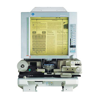
Summary of Contents for Minolta MS 6000
- Page 1 7664-0820-03 MS 6000 Operator's Manual...
-
Page 2: Safety Information
SAFETY INFORMATION This section contains detailed instructions on the operation and maintenance of this machine. To achieve optimum utility of this device, all operators should carefully read and follow the instructions in this manual. Please keep this manual in a handy place near the machine. - Page 3 • Do not modify this product, as a fire, electrical shock, or breakdown could result. If the product employs a laser, the laser beam source could cause blindness. • Do not attempt to remove the covers and panels which have been fixed to the product.
- Page 4 • If this product becomes inordinately hot or emits smoke, or unusual odor or noise, immediately turn OFF the power switch, unplug the power cord from the power outlet, and then call your authorized service representa- tive. If you keep on using it as is, a fire or electrical shock could result. •...
- Page 5 • Do not use flammable sprays, liquids, or gases near this product, as a fire could result. • Do not leave a toner unit or drum unit in a place within easy reach of children. Licking or ingesting any of these things could injure your health.
- Page 6 • Always use this product in a well ventilated location. Operating the product in a poorly ventilated room for an extended period of time could injure your health. Ventilate the room at regular intervals. • Whenever moving this product, be sure to disconnect the power cord and other cables.
- Page 7 Precautions for Routine • Do not store toner units, PC drum units, and other supplies and con- sumables in a place subject to direct sunlight and high temperature and humidity, as poor image quality and malfunction could result. • Do not attempt to replace the toner unit and PC drum unit in a place exposed to direct sunlight.
- Page 8 Welcome Thank you for choosing Minolta quality. For over 30 years Minolta has been a leader on the forefront of office equipment technology and service. Our desire has always been to bring you highly reliable products. We pledge to continue to provide you, our customer with our state of the art equipment, as well as full customer service for all our products.
- Page 9 [5] For best performance, only authorized Minolta supplies are recommended for use with this unit. Failure to use authorized Minolta supplies may cause damage to the unit, in which case the warranty may be rendered void.
-
Page 10: Laser Safety
Safety Information (MSP 3000 Printer) Laser Safety This printer is a page printer which operates by means of a laser. There is no possibility of danger from the laser, provided the printer is operated according to the instructions provided in this manual. Since radiation emitted by the laser is completely confined within protective housing, the laser beam cannot escape from the machine during any phase of user operation. -
Page 11: For Denmark
Safety Information (MSP 3000 Printer) For Denmark ADVARSEL: Usynlig laserstråling ved åbning, når sikkerhedsafbrydere er ude af funk- tion. Undgå udsttelse for stråling. Klasse 1 laser produkt der opfylder IEC60825 sikkerheds kravene. For Finland, Sweden VAROITUS!: Laitteen käyttäminen muulla kuin tässä käyttöohjeessa mainitulla tavalla saattaa altistaa käyttäjän turvallisuusluokan 1 ylittävälle näkymättömälle lasersäteilylle. -
Page 12: For Norway
Safety Information (MSP 3000 Printer) For Norway ADVARSEL: Dersum apparatet brukes på annen måte enn spesifisert i denne bruksanvis- ning, kan brukeren utsettes for unsynlig laserstråling som overskrider grensen for laser klasse 1. Dette er en halvleder laser. Maksimal effeckt til laserdiode er 8.8 × 10 W og bolgelengde er 770-810 nm. - Page 13 Safety Information (MSP 3000 Printer) OZONE RELEASE (For all Users) During printer operation, a small quantity of ozone is released. This amount is not large enough to cause any adverse affects or harm. However, be sure the room where the machine is being used has adequate ventilation, especially if you are printing a high volume of materi- als, or if the machine is being used continuously over a long period.
-
Page 14: Table Of Contents
Contents Chapter 1 Safety Notes 1. Installation Precautions ............1-2 Installation Site ..............1-2 Power Source ..............1-2 Grounding ................1-2 Space Requirements ............1-3 Operating Environment ............1-5 Using the Printer ..............1-5 Care of Printer Supplies ............. 1-5 2. - Page 15 Replenishing the Paper Supply .......... 3-4 Replacing the Toner Cartridge ........... 3-7 Clearing Misfeeds .............. 3-9 Solving Irregular Printing Problems ........ 3-12 Chapter 4 Miscellaneous 1. Specifications ................. 4-2 MS 6000 ................4-2 MS 6000 + MSP 3000 Printer ..........4-3...
- Page 16 Contents MS 6000 + MSP 2000 Printer ..........4-4 2. Initial Settings List ..............4-5 3. System Care ................4-8 Cleaning the Scanner ............4-8 Cleaning the MSP 3000 Printer ......... 4-9 For Key Operator’s Use ............4-10...
- Page 17 Contents...
-
Page 18: Chapter 1 Safety Notes
Chapter 1 Safety Notes This chapter provides precautions for use, a description of the oper- ating environment and conditions as well as instructions on how to turn the system ON and OFF. -
Page 19: Installation Precautions
1. Installation Precautions Installation Site Placement of the unit in the environment described below will ensure optimal performance throughout the long life of service for which it was designed. ! A well-ventilated place. ! An area which is free from ammonia or other organic gases. ! A place which has easy access to a power outlet so that the unit may be easily plugged in and unplugged. -
Page 20: Space Requirements
1. Installation Precautions Space Requirements Scanner There should be a clearance of the following dimensions between the wall and the rear of the unit as well as it’s right and left sides to provide ample space for the ventilation ports to dis- sipate heat. - Page 21 1. Installation Precautions Printer For ease of operation, maintenance and replenishment of supplies, the minimum clearance di- agrammed below is required. Install the unit in an area that allows easy access. MSP 3000 Printer 150mm 150mm 150mm 5-7/8" 5-7/8" 5-7/8" MSP 2000 Printer 394 mm (15-1/2") 700 mm (27-1/2")
-
Page 22: Operating Environment
1. Installation Precautions Operating Environment The environmental requirements for operating the system are as follows: Temperature: 10 °C to 35 °C (50 °F to 95 °F) with a fluctuation of 10 °C (18°F) per hour. Humidity: 15% to 85% with a fluctuation of 20% per hour. Using the Printer To ensure the optimum performance of the printer, follow the precautions listed below: ! NEVER open any Cover, or turn OFF the printer during printing. -
Page 23: Turning The Power On And Off
2. Turning the Power On and Off Turning ON Press the Power Switch of the The Control Panel displays a blinking scanner to the I (ON) position. “1” and the machine starts to warm up. The machine is ready to read data when the “1”... -
Page 24: Turning Off
Multi- Print Display LEDs light up sequentially, clockwise. * The default setting for the Auto Power MSP 2000 Printer Save and Auto Projection Lamp OFF functions is “Disabled.” Consult your Minolta authorized dealer for more in- formation. - Page 25 Memo...
-
Page 26: Chapter 2 Scanner
Chapter 2 Scanner This chapter identifies different parts of the Scanner and explains its operation. -
Page 27: System Overview
1. System Overview Scanner Projection Lens Single Lens 7.5× Zoom Lens 9-16× 13-27× 23-50× • Prism Unit • Counter Kit • Manual Frame • PC Interface Kit Masking Kit • Foot Switch Kit Film Carrier Auto-retrival Controller FC-5 RFC-21 MARS C-4 RFC-9B RFC-15A MARS MINI 2... -
Page 28: System Configuration
Each scanner is designed exclusively for use with its respective Printer. Contact your Minolta authorized dealer in order to change the scanner that is connected to your printer. For instructions on operating the MSP 2000 printer, see the Operator’s Manual that came with the printer. -
Page 29: Parts Of The Scanner
2. Parts of the Scanner Screen: The image taken from the film is projected here for view- ing. The frame on the Screen marks the data reading range. Control Panel: Many operations are controlled from the keys and indica- tors provided here. Image Rotation Knob: Used to turn the Prism Unit built into the Scanner, turning the image on the Screen. -
Page 30: Control Panel Keys And Indicators
3. Control Panel Keys and Indicators Control Panel (Basic) Output Selection Tray Cassette1 Cassette2 Auto Skew Correction Centering/Fit Auto Masking Manual Text Print Mode Fine Photo Resolution Auto Film Type Nega Posi Job Recall Darker Zoom + Auto Zoom clr Lighter Zoom - PC/PR... - Page 31 ON or OFF. When this function is applied, the Auto Skew Correction indicator will turn on and the system will cor- rect any skew of the image during printing. * After printing, the skew can be reset or retained. Con- tact your Minolta authorized dealer for more informa- tion.
- Page 32 3. Control Panel Keys and Indicators Centering/Fit Key: When this key is pressed, the setting rotates from OFF to the Centering and Fit functions. When Auto Masking, Trimming, or Masking are set to off, Auto Masking will automatically be enabled when Center- ing is selected.
- Page 33 3. Control Panel Keys and Indicators Masking Key: When pressed, this key rotates from OFF to the Auto, Trimming or Masking functions. Each time this key is pressed, selection is switched in order of "OFF → Auto Masking → Manual Trimming → Man- ual Masking →...
- Page 34 3. Control Panel Keys and Indicators Film Type Key: Rotates between Auto, Nega, and Posi each time the key is pressed. 1) Auto: The scanner automatically determines between the film type options of negative or positive for print production. 2) Nega: Select when using negative film. Dark and light values of the print will be reversed.
- Page 35 2-10 3. Control Panel Keys and Indicators Memory Input Key: To store one of the following functions into the memory of the Scanner, first set one of the functions on Control Panel and then press this button with the head of a pen or other device.
-
Page 36: Control Panel (Shift Function)
2-11 3. Control Panel Keys and Indicators Control Panel (Shift Function) Output Selection Tray Cassette1 Cassette2 Auto Skew Correction Centering/Fit Auto Masking Manual Text Print Mode Fine Photo Resolution Auto Film Type Nega Posi Job Recall Darker Zoom + Auto Zoom clr Lighter Zoom -... - Page 37 2-12 3. Control Panel Keys and Indicators Lamp Illuminance Key: When this key is pressed together with the Shift Key, the illumination of the screen is adjusted. When this key is continuously pressed, the screen is gradually darkened un- til it is turned OFF. When any key is pressed then, the illu- mination returns to the maximum level.
-
Page 38: When (Misfeed/Call-Tech.-Rep. Code) Lights Up
2-13 3. Control Panel Keys and Indicators When (Misfeed/Call-Tech.-Rep. Code) Lights up This indicates that a paper misfeed or malfunction has occurred in the system. Check the code shown on the Multi-Print Display and perform the misfeed clearing procedure or the Call- Tech.-Rep. - Page 39 A Communication malfunction (PC) NOTE After turning the power to the system OFF and unplugging its power cord from the electrical outlet, contact your Minolta authorized dealer, being sure to provide him or her with the currently displayed code (Above code).
-
Page 40: Image Processing Functions
2-15 4. Image Processing Functions Description Screen Image Print Image Auto Masking (1 Frame) The system masks the black bands that run along the edges of the image. Trimming (1 Frame) The system masks everything but the center of the im- age. - Page 41 (portrait or landscape) of the image on the Screen and prints it as necessary. If you would like to use this function, please contact your Minolta authorized Technical Representative. Image Zoom The system magnifies the screen image according to the size of paper being used. The range of magnifica- tion is 1.55x for Ledger, 1.27x for Legal, 1.41x for A3...
-
Page 42: Printing/Scanning
2-17 5. Printing/Scanning Here is an outline of the printing procedure: 1. Load the film The procedure for loading film is determined by the type of Film Carrier (optional) that is being used. Review the Operator’s Manual that came with your Film Carrier for more information. -
Page 43: Selecting A Projection Lens
2-18 6. Selecting a Projection Lens Projection Lenses come in the following four types. Select the one that corresponds to the film being used. Projection Lens Types Type 1: 7.5× Type 1: 9 to 16× Type 2: 13 to 27× Type 3: 23 to 50×... -
Page 44: Replacing The Projection Lens
2-19 7. Replacing the Projection Lens To install a Lens with a magnification different from that already installed in the machine, follow the procedure given below. Take hold of the Prism Holder Lever Pull out the Brightness Select Lever and pull it up to raise the Prism and slide it to a position appropriate Holder. -
Page 45: Zooming And Focusing
2-20 8. Zooming and Focusing Zooming of the Screen Image Focusing of the Screen Image Rotate the Zooming Ring Dial to Rotate the Focusing Ring Dial to bring the bring the image on the Screen into image on the Screen into focus. print size frame. -
Page 46: Image Rotation
2-21 9. Image Rotation To turn the image on the Screen, turn the Image Rotation Knob. Auto Image Rotation: Auto Skew Correction Turn the Image Rotation Knob on the bot- If the Auto Skew Correction Key is turned tom right of the Screen Frame to turn the ON, the system will automatically correct image. -
Page 47: Selecting The Film Type
2-22 10. Selecting the Film Type Auto Posi (positive film) The system will automatically If positive film is to be used, press the determine the polarity of the film Film Type Key to select Posi. being used when Auto is selected Posi with the Film Type key. -
Page 48: Selecting The Image Density
2-23 11. Selecting the Image Density Using Auto Exposure Using Manual Exposure Depress the Exposure Mode Select Depress the Exposure Mode Select Button as necessary to select the Auto Button as necessary to select the Exposure Mode. Manual Exposure mode. The LED to the left of the key lights The LED to the left of the key lights up green when the Auto Exposure... -
Page 49: Setting The Number Of Prints To Be Made
2-24 12. Setting the Number of Prints to be Made To Entry the Number of Prints Set the desired number using the Multi-Print Key. NOTE This function is only available on the PR mode. The number that can be entered is 19 max. Correcting Entry To correct an entry, depress the Clean Button, which resets the number on the Multi-Print Dis- play to “1”. -
Page 50: Selecting The Output Format
2-25 13. Selecting the Output Format Press the Output Selection Key to select the paper source and print format. Output Selection Tray Cassette1 Cassette2 Selecting the paper source Tray: Prints the film image on paper from the print tray. Cassette 1: Prints the film image on paper from the cassette 1. Cassette 2: Prints the film image on paper from the cassette 2. -
Page 51: Selecting The Print Format
2-26 13. Selecting the Output Format Selecting the print format Display Paper Feeding Description Light OFF Lengthwise Prints the on-screen lengthwise area. Crosswise Prints the on-screen crosswise area. Light ON Lengthwise Prints the on-screen crosswise area. Crosswise Prints the on-screen lengthwise area. Blinking Lengthwise Prints the on-screen image by automatically... -
Page 52: Using Auto Masking
2-27 14. Using Auto Masking The Auto Masking function prevents the frame (non-image area) of a film image from appear- ing on the print. Selecting Auto Masking Press the Auto Masking key to turn ON this function. Auto Masking Manual Operating Conditions for Auto Masking A. -
Page 53: Manual Masking Panels (Optional)
2-28 15. Manual Masking Panels (Optional) Vertical Area Indication Use to specify the vertical print (scan) area of the image on Panel: the screen. There are 42 lights placed at 7mm intervals. The lights create a pattern when lit specifying the area on the screen that will be printed. -
Page 54: Using Manual Masking
2-29 16. Using Manual Masking The optional Manual Frame Masking Kit allows you to specify an area for printing of the dis- played image through two separate features, Trimming and Masking. Selecting Trimming Defining the Print Area Press the (manual) Masking key to Define the end points for both the select (Trimming). -
Page 55: Clearing A Defined Print (Scan) Area
2-30 16. Using Manual Masking Clearing a Defined Print (Scan) Area Press the Vertical and Horizontal Area Clear keys to clear the defined print (scan) area. 1: Horizontal Area Clear Key 2: Vertical Area Clear Key Selecting Masking Press the (manual) Masking key to select (Masking) when you want to mask a given area of the image. -
Page 56: Using Centering And Fit
2-31 17. Using Centering and Fit Once the image on the Screen has been either “manually trimmed” or “auto masked”, the Im- age Centering function moves the image to the center of the print. The Fit function however, fits the image on the Screen onto the entire surface of the print. Screen Image Print Image Centering: OFF... -
Page 57: Using The Cycle Print Mode
2-32 18. Using the Cycle Print Mode This function automatically scans the next image following a preset period of time. Images are manually loaded onto the Carrier Glass in between cycles. This is a system setting that must be entered by an authorized dealer. If you want to use the Cycle Print Mode, ask your Tech. -
Page 58: Operating In The Cycle Print Mode
2-33 18. Using the Cycle Print Mode Operating in the Cycle Print Mode After entering the Cycle Print Mode, While the pause function is enabled, press the Start key to start. it is possible to exit the Cycle Print Mode by pressing the Clear key a second time (the value displayed in the “No. -
Page 59: Selecting The Connection Mode
2-34 19. Selecting the Connection Mode The Scanner connection can be selected between PR (connection to the Printer) and PC (con- nection to the PC). * For the connection to the PC, the optional interface kit is required. Hold down the Shift Key and the PC/PR Key together for over one second. PC/PR Shift PC mode:... -
Page 60: Selecting The Resolution
2-35 20. Selecting the Resolution The resolution for scanning (printing) can be selected. Press the Shift Key and the Resolution Key together. The present resolution is displayed. Print Mode Resolusion Shift Press the Resolution Key while holding down the Shift Key to set the resolution. Connection mode Resolution Display... -
Page 61: Registering The Job Program
2-36 21. Registering the Job Program The present setting state can be registered in up to 3 program registration locations (1J, 2J and 3J). Press the Memory Input Key in the Setting mode. 1J starts blinking. Memory Input Key To change the program registration location, press the Multi-Print Key. The display is switched in order of 1J →... -
Page 62: Calling The Job Program
2-37 22. Calling the Job Program The registered Job program can be called. Press the Shift Key and the Job Recall Key together. Job Recall Shift Each time the Job Recall Key is pressed while the Shift Key is held down, the display is switched in order of 1J →... -
Page 63: Using The Electrical Zoom
2-38 23. Using the Electrical Zoom In addition to the zooming by the Lens, the Electrical Zoom function has been provided for magnifying the image when it is printed. Zoom + When the Zoom+ key is pressed together with the Shift Key, the magnification is increased by an increment of 0.01X (up to 2.00X). -
Page 64: Clearing The Zoom Magnification
2-39 23. Using the Electrical Zoom Clearing the Zoom magnification When the Zoom clr key is held down together with the Shift Key for over one second, the standard magnification is resumed. Zoom clr Shift The standard magnification is fixed according to the selected paper size. Paper size Ledger Legal... -
Page 65: Adjusting The Illumination Of The Screen
2-40 24. Adjusting the Illumination of the Screen The illumination of the screen can be adjusted. Hold down the Shift Key and the Illumination Key together to adjust the illumination of the screen. Shift The screen is gradually darkened until it is turned OFF. When any key is pressed, the illumi- nation returns to the maximum level. -
Page 66: Replacing The Projection Lamp
2-41 25. Replacing the Projection Lamp Use the following procedure to replace the Projection Lamp whenever a reduction in bright- ness on the screen is detected or whenever the lamp burns out. Make sure that the replace- ment lamp is specified for use with this scanner. (DC20V 150W DDL type) If the Projection Lamp should burn out during a print operation, an L2 code will appear and the print job will stop (a blank piece of paper may be output depending upon the stage of the job). - Page 67 2-42 25. Replacing the Projection Lamp Insert a new Projection Lamp so that Slide the Projection Unit back into the mark on its base is facing the machine. upwards. Make sure that the new NOTE Projection Lamp is inserted securely so that there is no gap between the If the Projection Unit is not properly Projection Lamp and the Lamp...
-
Page 68: Chapter 3 Msp 3000 Printer
Chapter 3 MSP 3000 Printer This chapter identifies the different parts of the system and explains the MSP 3000 printer’s operational procedures. -
Page 69: Parts Of The Printer
1. Parts of the Printer Upper Unit Lock Use to open the Upper Unit. Release Lever: Power Indicator: Light indicates when the Printer is turned ON. Print Tray: Prints are output from the Printer, face down onto this tray which can hold up to 500 sheets of standard paper. Paper Guides: Slide the guides to secure the paper stack. - Page 70 1. Parts of the Printer Upper Unit: Open to replace the Imaging Cartridge and to clear misfed sheets of paper. Image Transfer Transfers the image onto the sheet of paper. Be careful to avoid touching it with your bare hands. Roller: Fusing Unit: Permanently fixes the image onto the sheet of paper.
-
Page 71: Troubleshooting And Maintenance
2. Troubleshooting and Maintenance Replenishing the Paper Supply Use only the following types of paper: Type Plain and recycled paper (weight 16 to 24 lbs. / 60 to 90 g/m Standard sizes: 11" × 17", 8-1/2" × 11", 8-1/2" × 14" (or A3, B4, A4). Size Capacity Paper Feeding Tray: 8-1/2"... - Page 72 2. Troubleshooting and Maintenance Loading Paper into the Paper Feeding Tray (Tray) Swing down the Paper Feeding Tray. NOTE • Make sure that the paper stack does not exceed the Maximum Level Indicator. Fan the paper stack thoroughly and • Load a new paper stack only after the align the edges.
- Page 73 2. Troubleshooting and Maintenance Loading Paper in the Paper Cassette Pull the cassette out of the Printer and NOTE open the Cover. • Make sure that the paper stack does not exceed the Maximum Level Indicator. • Load a new paper stack only after the old one has run out.
-
Page 74: Replacing The Toner Cartridge
2. Troubleshooting and Maintenance Replacing the Toner Cartridge Open the upper unit by pulling the Remove the seal from the Imaging Upper Unit Lock Release Lever Cartridge by pulling it steadily forward. straight out. Remove the old Imaging Cartridge Shake the Imaging Cartridge four or from the printer. - Page 75 2. Troubleshooting and Maintenance Close the Upper Unit. NOTE Push the Print Tray in before opening the Upper Unit.
-
Page 76: Clearing Misfeeds
2. Troubleshooting and Maintenance Clearing Misfeeds • If the Misfeed Code (P0) lights up: The Paper Feeding Tray is loaded with paper other than 8-1/2"×11" (or A4). Load 8-1/2"×11" (or A4) paper in the tray and open and close the Upper Unit. •... - Page 77 3-10 2. Troubleshooting and Maintenance Clearing a Misfeed from the Paper Cassette Open the Upper Unit by pulling the Remove the sheet(s) of paper that Upper Unit Lock Release Lever caused the misfeed as shown. forward. Check that no misfed paper is left in the Printer and then reinstall the NOTE Imaging Cartridge.
- Page 78 3-11 2. Troubleshooting and Maintenance Clearing a Misfeed from inside the Printer Open the Upper Unit by pulling the If the misfeed occurred after the sheet Upper Unit Lock Release Lever of paper entered the Fusing Unit, forward. gently pull the misfed sheet toward you and out as shown.
-
Page 79: Solving Irregular Printing Problems
3-12 2. Troubleshooting and Maintenance Solving Irregular Printing Problems Use the following procedures to fix minor printing problems. If print quality does not improve after implementing the procedures below, contact your Minolta authorized dealer. Symptom Cause Action Light image Print density is not properly Change the print density set. - Page 80 Action Symptom Uneven image density Toner in the Imaging Car- Remove the Imaging Car- tridge is not evenly distrib- tridge, shake it several uted. times and replace. Blank print The Printer has malfunc- Contact your Minolta au- tioned. thorized dealer.
- Page 81 Memo...
-
Page 82: Chapter 4 Miscellaneous
Chapter 4 Miscellaneous This chapter contains the specifications of the unit as well as provides care and maintenance instructions. -
Page 83: Specifications
1. Specifications MS 6000 Type: Desk-Top Type Microfilm Scanner Resolution: 200, 300, 400, 600, 800 dpi (PC Mode) 400, 600 dpi (PR Mode: When MSP 3000 Printer is connected) 400 dpi (PR Mode: When MSP 2000 Printer is connected) Output Scale:... -
Page 84: Ms 6000 + Msp 3000 Printer
1. Specifications MS 6000 + MSP 3000 Printer Type: Microfilm Scanner Printer System Printing Method: Laser Electrostatic Resolution: 400, 600 dpi Developing System: Minolta Fine Micro-Toning (Fine-MT) System 8-1/2" × 11" (or A4) Crosswise, 11" × 17" (or A3) Lengthwise Print Size: 8-1/2"... -
Page 85: Ms 6000 + Msp 2000 Printer
1. Specifications MS 6000 + MSP 2000 Printer Type: Microfilm Scanner Printer System Printing Method: Laser Electrostatic Resolution: 400 dpi Developing System: Minolta Fine Micro-Toning (Fine-MT) System 8-1/2" × 11" (or A4) Print Size: 8 sheets per minute (8-1/2" × 11" or A4) Print Speed: 19 seconds (8-1/2"... -
Page 86: Initial Settings List
This system offers two types of settings: one is the user settings that are made by the user on the control panel and the other is the system settings that are made by the Minolta authorized dealer. Here is a list of factory settings for these two setting types. - Page 87 2. Initial Settings List System Settings Description Selection Initial Setting Auto Skew Cor- Determines whether or not to retain the Retained rection Retain original (uncorrected) skew of a screen √ image after the print has been made. retained √ Machine ID When two scanners are connected to one Disabled Printing...
- Page 88 The paper source must be refilled or the paper source must be switched by pressing the Output Selec- tion Key in order to resume printing. * To change any of the system settings described above, contact your Minolta authorized dealer.
-
Page 89: System Care
3. System Care The system should be cleaned on a daily basis for optimal operating conditions. Cleaning the Scanner Screen Carrier Glass (Option) With a damp cloth, clean and remove With a damp cloth, clean and remove any dust or debris from the surface of any dust or debris from the surface of the Screen. -
Page 90: Cleaning The Msp 3000 Printer
3. System Care Cleaning the MSP 3000 Printer Clean the Printer at regular intervals. NOTE • Before cleaning the Printer, turn OFF the power and unplug the cord from the power outlet. • Use a soft cloth and NEVER use abrasives or corrosive detergents. Exterior Panels Clean the exterior panels with a soft, dry cloth. -
Page 91: For Key Operator's Use
For Key Operator’s Use When you need to call for service, the Key Operator should be prepared to provide the fol- lowing information to your Minolta authorized Dealer. 1. Your Company Name, Address, Telephone Number, Department Name, Floor Number, Machine Location, etc. - Page 92 Copyright 2001 MINOLTA CO., LTD The information contained in this manual is subject to change without notice to incorporate improvements made on the product or products the manual covers. MINOLTA CO., LTD. Image Information Products Marketing Headquarters 2001.3 3-13, 2-chome, Azuchi-machi, Chuo-ku, Osaka. 541-8556, Japan...