Table of Contents
Advertisement
Quick Links
Advertisement
Table of Contents

Related Manuals for Minolta MS6000 MK II


Summary of Contents for Minolta MS6000 MK II
-
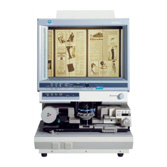
Page 1: Ms6000 Mkii
MS6000 MKII User ’ s Guide... -
Page 3: Safety Information
SAFETY INFORMATION This section contains detailed instructions on the operation and maintenance of this machine. To achieve optimum utility of this device, all operators should carefully read and follow the instructions in this manual. Please keep this manual in a handy place near the machine. - Page 4 P-ii SAFETY INFORMATION • Do not modify this product, as a fire, electrical shock, or break- down could result. If the product employs a laser, the laser beam source could cause blindness. • Do not attempt to remove the covers and panels which have been fixed to the product.
- Page 5 P-iii SAFETY INFORMATION Do not place a flower vase or other container that contains water, or metal clips or other small metallic objects on this product. Spilled water or metallic objects dropped inside the product could result in a fire, electrical shock, or breakdown. Should a piece of metal, water, or any other similar foreign matter get inside the product, immediately turn OFF the power switch, unplug the power cord from the power outlet, and then call your...
- Page 6 P-iv SAFETY INFORMATION • Do not use flammable sprays, liquids, or gases near this product, as a fire could result. • Do not leave a toner unit or drum unit in a place within easy reach of children. Licking or ingesting any of these things could injure your health.
- Page 7 SAFETY INFORMATION • Always use this product in a well ventilated location. Operating the product in a poorly ventilated room for an extended period of time could injure your health. Ventilate the room at regular intervals. • Whenever moving this product, be sure to disconnect the power cord and other cables.
- Page 8 P-vi SAFETY INFORMATION Do not touch or scratch the surface of the toner unit developing roller and the PC drum, as poor image quality could result. Use the supplies and consumables recommended by the dealer. Use of any supply or consumable not recommended could result in poor image quality and breakdown.
- Page 9 Welcome This User’s Guide explains how to operate the unit and replenish its supplies. It also gives some troubleshooting tips as well as general precautions to be observed when operating the unit. To ensure the best performance and effective use of your unit, read this User’s Guide carefully until you familiarize yourself thoroughly with the unit's operation and features.
- Page 10 Notes to Operators and Key Operators The following safety rules should be observed: [1] The unit should be kept free from moisture, dirt, dust and exposure to heat and direct sun- light at all times. [2] Keep hands, hair and clothing away from rollers and other moving parts. [3] Before removing the Projection Lamp Unit, confirm that the machine is turned “OFF”.
- Page 11 Notes to Operators and Key Operators Interference-Causing Equipment Standard (ICES-003 ISSUE 4) (For Canada Users) This Class A digital apparatus complies with Canadian ICES-003. Cet appareil numérique de la classe A est conforme à la norme NMB-003 du Canada. CE Marking (Declaration of Conformity) (For European Users) This product complies with the following EU directives: 2006/95/EC and 2004/108/EC directives.
- Page 12 Safety Information (MSP 3500 Printer) Laser Safety This printer is a page printer which operates by means of a laser. There is no possibility of danger from the laser, provided the printer is operated according to the instructions provided in this manual. Since radiation emitted by the laser is completely confined within protective housing and ex- ternal covers, the laser beam cannot escape from the machine during any phase of user oper- ation.
-
Page 13: For United States
Safety Information (MSP 3500 Printer) For United States CDRH Regulations This printer is certified as a Class I laser product under the Regulation Performance Standard according to the Food, Drug, and Cosmetic Act of 1990. Compliance is mandatory for laser products marketed in the United States, and is reported to the Center for Devices and Radiological Health (CDRH) of the U.S. -
Page 14: For Norway
Safety Information (MSP 3500 Printer) For Finland, Sweden VAROITUS!: Laitteen käyttäminen muulla kuin tässä käyttöohjeessa mainitulla tavalla saattaa altistaa käyttäjän turvallisuusluokan 1 ylittävälle näkymättömälle lasersäteilylle. VARNING: Om apparaten används på annat sätt än i denna bruksanvisning specificerats, kan använderen utsattasr för osynling laserstrålnig, som överskrider gränsen för laserklass VARO: Avattaessa ja suojalukitus ohitettaessa olet alttiina nakymattomalle laser- sateilylle. -
Page 15: Warning Label
Safety Information (MSP 3500 Printer) WARNING LABEL • Three laser caution labels are attached to the inside of the machine as shown below. - Page 16 viii Safety Information (MSP 3500 Printer) OZONE RELEASE (For all Users) During printer operation, a small quantity of ozone is released. This amount is not large enough to cause any adverse affects or harm. However, be sure the room where the machine is being used has adequate ventilation, especially if you are printing a high volume of materi- als, or if the machine is being used continuously over a long period.
- Page 17 Safety Information (MSP 3000 Printer) Laser Safety This printer is a page printer which operates by means of a laser. There is no possibility of danger from the laser, provided the printer is operated according to the instructions provided in this manual. Since radiation emitted by the laser is completely confined within protective housing, the laser beam cannot escape from the machine during any phase of user operation.
- Page 18 Safety Information (MSP 3000 Printer) For Denmark ADVARSEL: Usynlig laserstråling ved åbning, når sikkerhedsafbrydere er ude af funk- tion. Undgå udsttelse for stråling. Klasse 1 laser produkt der opfylder IEC60825 sikkerheds kravene. For Finland, Sweden VAROITUS!: Laitteen käyttäminen muulla kuin tässä käyttöohjeessa mainitulla tavalla saattaa altistaa käyttäjän turvallisuusluokan 1 ylittävälle näkymättömälle lasersäteilylle.
- Page 19 Safety Information (MSP 3000 Printer) For Norway ADVARSEL: Dersum apparatet brukes på annen måte enn spesifisert i denne bruksanvis- ning, kan brukeren utsettes for unsynlig laserstråling som overskrider grensen for laser klasse 1. Dette er en halvleder laser. Maksimal effeckt til laserdiode er 8.8 × 10 W og bolgelengde er 770-810 nm.
- Page 20 Safety Information (MSP 3000 Printer) OZONE RELEASE (For all Users) During printer operation, a small quantity of ozone is released. This amount is not large enough to cause any adverse affects or harm. However, be sure the room where the machine is being used has adequate ventilation, especially if you are printing a high volume of materi- als, or if the machine is being used continuously over a long period.
-
Page 21: Table Of Contents
Contents Chapter 1 Safety Notes............1-1 1. Installation Precautions ............1-2 Installation Site ..............1-2 Power Source ..............1-2 Grounding ................1-2 Space Requirements ............1-3 Operating Environment ............1-5 Using the Printer ..............1-5 Care of Printer Supplies ............. 1-5 2. - Page 22 Contents 13. Selecting the Output Format ..........2-27 Selecting the paper source ..........2-27 Selecting the print format ..........2-28 14. Using Auto Masking ............2-29 Selecting Auto Masking ........... 2-29 Operating Conditions for Auto Masking ......2-29 15. Manual Masking Panels (Optional) ........2-30 16.
- Page 23 Contents Clearing a Misfeed from the Paper Feeding Tray .... 3-14 Clearing a Misfeed from the Paper Cassette ....3-15 Clearing a Misfeed from inside the Printer ...... 3-16 Clearing a Misfeed from output bin ......... 3-18 Chapter 4 MSP 3000 Printer ..........4-1 1.
- Page 24 Contents PR Mode : MSP 3000 Printer ..........7-4 2. Initial Settings ................ 7-5 User Settings on the Control Panel ........7-5 User Mode ................7-6 Entering and Leaving the User Mode ........ 7-7 Settings in Each User Mode Function ....... 7-8 System Settings by the dealer ..........
-
Page 25: Chapter 1 Safety Notes
Chapter 1 Safety Notes This chapter provides precautions for use, a description of the oper- ating environment and conditions as well as instructions on how to turn the system ON and OFF. -
Page 26: Installation Precautions
1. Installation Precautions Installation Site Placement of the unit in the environment described below will ensure optimal performance throughout the long life of service for which it was designed. A well-ventilated place. An area which is free from ammonia or other organic gases. A place which has easy access to a power outlet so that the unit may be easily plugged in and unplugged. -
Page 27: Space Requirements
1. Installation Precautions Space Requirements Scanner There should be a clearance of the following dimensions between the wall and the rear of the unit as well as it’s right and left sides to provide ample space for the ventilation ports to dis- sipate heat. - Page 28 1. Installation Precautions Printer MSP 3500 Printer: For ease of operation, maintenance and replenishment of supplies, the minimum clearance di- agrammed below is required. Install the unit in an area that allows easy access. 457 mm or 18" 200 mm or 8" 200 mm or 8"...
-
Page 29: Operating Environment
1. Installation Precautions Operating Environment The environmental requirements for operating the system are as follows: Temperature: 10 °C to 35 °C (50 °F to 95 °F) with a fluctuation of 10 °C (18°F) per hour. Humidity: 15% to 85% with a fluctuation of 20% per hour. Using the Printer To ensure the optimum performance of the printer, follow the precautions listed below: NEVER open any Cover, or turn OFF the printer during printing. -
Page 30: Turning The Power On And Off
2. Turning the Power On and Off Turning ON Press the Power Switch of the The Control Panel displays a blinking scanner to the I (ON) position. “1” and the unit starts to warm up. The unit is ready to read data when the “1”... -
Page 31: Turning Off
2. Turning the Power On and Off Turning OFF Press the Power Switch of the scanner to the O (OFF) position. Press the Power Switch of the printer to the O (OFF) position. NOTE The printer and scanner can be turned ON and OFF at the same time by employing a cord that is equipped with an on/off switch saving both time and energy. -
Page 32: Auto Power Save Mode
3. Auto Power Save Mode The unit enters the Auto Power Save mode if it is left to stand idle for a predetermined period of time. When the unit enters the Auto Power Save mode, power to the Scanner projection lamp and the printer heater is automatically shut down to save power consumption. -
Page 33: Chapter 2 Scanner
Chapter 2 Scanner This chapter identifies different parts of the Scanner and explains its operation. -
Page 34: System Overview
1. System Overview Scanner Projection Lenses Single Lens 7.5× Zoom Lens 9-16× 13-27× 23-50× • Prism Unit • Counter Kit • Manual Frame • USB I/F Kit Masking Kit • Foot Switch Kit Film Carriers Controllers FC-5 RFC-15A MARS MINI CONTROLLER 2 UC-2 RFC-15M... -
Page 35: System Configuration
1. System Overview System Configuration This Scanner is available in the following configurations. PR Mode (connected to a printer) The Scanner is connected to a dedicated printer (MSP 3500 or MSP 3000), allowing scanned images to be printed out directly. PC Mode (connected to a personal computer) The Scanner is connected to a personal computer and the scanned images can be uploaded to the computer. -
Page 36: Parts Of The Scanner
2. Parts of the Scanner Screen: The image taken from the film is projected here for view- ing. The frame on the Screen marks the data reading range. Control Panel: Many operations are controlled from the keys and indica- tors provided here. Image Rotation Knob: Used to turn the Prism Unit built into the Scanner, turning the image on the Screen. -
Page 37: Control Panel Keys And Indicators
3. Control Panel Keys and Indicators Control Panel (Basic) Output Selection Tray Cassette1 Cassette2 User Mode Auto Skew Correction Centering/Fit Auto Masking Manual Text Print Mode Fine Photo Resolution Auto Film Type Nega Posi Job Recall Darker Zoom + Auto Zoom clr Lighter Zoom -... - Page 38 3. Control Panel Keys and Indicators Output Selection Key: Select the paper feeding source according to the format of the film image that is being reflected in the screen. * This key is only available on the PR mode. when this lamp is lit: A 90 degree image rotation is performed during printing.
- Page 39 3. Control Panel Keys and Indicators Centering/Fit Key: When this key is pressed, the setting rotates from OFF to the Centering and Fit functions. When Auto Masking, Trimming, or Masking are set to off, Auto Masking will automatically be enabled when Center- ing is selected.
- Page 40 3. Control Panel Keys and Indicators Masking Key: When pressed, this key rotates from OFF to the Auto, Trimming or Masking functions. Each time this key is pressed, selection is switched in order of “OFF → Auto Masking → Manual Trimming → Man- ual Masking →...
- Page 41 3. Control Panel Keys and Indicators Film Type Key: Rotates between Auto, Nega, and Posi each time the key is pressed. 1) Auto: The scanner automatically determines between the film type options of negative or positive for print production. 2) Nega: Select when using negative film. Dark and light values of the print will be reversed.
- Page 42 2-10 3. Control Panel Keys and Indicators Memory Input Key: To store one of the following functions into the memory of the Scanner, first set one of the functions on Control Panel and then press this button with the head of a pen or other device.
-
Page 43: Control Panel (Shift Function)
2-11 3. Control Panel Keys and Indicators Control Panel (Shift Function) Output Selection Tray Cassette1 Cassette2 User Mode Auto Skew Correction Centering/Fit Auto Masking Manual Text Print Mode Fine Photo Resolution Auto Film Type Nega Posi Job Recall Darker Zoom + Auto Zoom clr Lighter... - Page 44 2-12 3. Control Panel Keys and Indicators User Mode Key: Pressing this key together with the Shift Key enters the unit ☞ into the User Mode. See p. 7-6 User Mode. Lamp Illuminance Key: When this key is pressed together with the Shift Key, the illumination of the screen is adjusted.
-
Page 45: When (Misfeed/Call-Tech.-Rep. Code) Lights Up
2-13 3. Control Panel Keys and Indicators When (Misfeed/Call-Tech.-Rep. Code) Lights up This indicates that a paper misfeed or malfunction has occurred in the system. Check the code shown on the Multi-Print Display and perform the misfeed clearing procedure or the Call- Tech.-Rep. - Page 46 2-14 3. Control Panel Keys and Indicators Code Description The Scanner is connected to the PC and ready for scanning by pressing the Start Key. This display is blinking when the Scanner is in operation. The Scanner is not connected to the PC. Turn ON the PC or connect the Scanner to the PC with the interface cable.
-
Page 47: Misfeed Clearing Procedure
2-15 3. Control Panel Keys and Indicators Misfeed Clearing Procedure Locate the misfeed using the code and perform the misfeed clearing procedure. Code Description The wrong size paper has been loaded in the Paper Feeding Tray. Load the set size paper in the set direction. This code also ap- pears when two or more sheets of paper are taken up at the same time. - Page 48 2-16 3. Control Panel Keys and Indicators Call-Tech.-Rep. Procedure A malfunction has occurred in the system. * Only MSP3500 displays the code. Location Code Description Optical path switching failure Scanner A Scanning malfunction A Fan Motor malfunction A Fusing Unit malfunction An Laser malfunction A Polygon Motor malfunction Printer...
-
Page 49: Image Processing Functions
2-17 4. Image Processing Functions Description Screen Image Print Image Auto Masking (1 Frame) The system masks the black bands that run along the edges of the image. Trimming (1 Frame) The system masks everything but the center of the image. - Page 50 2-18 4. Image Processing Functions Description Screen Image Print Image Auto Film Format Select Print The unit automatically determines the format (por- trait or landscape) of the image on the Screen and prints it as necessary. If you would like to use this function, please con- tact the authorized Technical Representative.
-
Page 51: Printing/Scanning
2-19 5. Printing/Scanning Here is an outline of the printing procedure: 1. Load the film The procedure for loading film is determined by the type of Film Carrier (optional) that is being used. Review the Operator’s Manual that came with your Film Carrier for more information. -
Page 52: Selecting A Projection Lens
2-20 6. Selecting a Projection Lens Projection Lenses come in the following four types. Select the one that corresponds to the film being used. Projection Lens Types Type 1: 7.5× Type 1: 9 to 16× Type 2: 13 to 27× Type 3: 23 to 50×... -
Page 53: Replacing The Projection Lens
2-21 7. Replacing the Projection Lens To install a Lens with a magnification different from that already installed in the unit, follow the procedure given below. Take hold of the Prism Holder Lever Pull out the Brightness Select Lever and pull it up to raise the Prism and slide it to a position appropriate Holder. -
Page 54: Zooming And Focusing
2-22 8. Zooming and Focusing Zooming of the Screen Image Focusing of the Screen Image Rotate the Zooming Ring Dial to Rotate the Focusing Ring Dial to bring the bring the image on the Screen into image on the Screen into focus. print size frame. -
Page 55: Image Rotation
2-23 9. Image Rotation To turn the image on the Screen, turn the Image Rotation Knob. Auto Image Rotation: Auto Skew Correction Turn the Image Rotation Knob on the bot- If the Auto Skew Correction Key is turned tom right of the Screen Frame to turn the ON, the system will automatically correct image. -
Page 56: Selecting The Film Type
2-24 10. Selecting the Film Type Auto Posi (positive film) The system will automatically If positive film is to be used, press the determine the polarity of the film Film Type Key to select Posi. being used when Auto is selected Posi with the Film Type key. -
Page 57: Selecting The Image Density
2-25 11. Selecting the Image Density Using Auto Exposure Using Manual Exposure Depress the Exposure Mode Select Depress the Exposure Mode Select Button as necessary to select the Auto Button as necessary to select the Exposure Mode. Manual Exposure mode. The LED to the left of the key lights The LED to the left of the key lights up green when the Auto Exposure... -
Page 58: Setting The Number Of Prints To Be Made
2-26 12. Setting the Number of Prints to be Made To Entry the Number of Prints Set the desired number using the Multi-Print Key. NOTE This function is only available on the PR mode. The number that can be entered is 19 max. Correcting Entry To correct an entry, depress the Clean Button, which resets the number on the Multi-Print Dis- play to “1”. -
Page 59: Selecting The Output Format
2-27 13. Selecting the Output Format Press the Output Selection Key to select the paper source and print format. Output Selection Tray Cassette1 Cassette2 Selecting the paper source Tray: Prints the film image on paper from the print tray. Cassette 1: Prints the film image on paper from the cassette 1. Cassette 2: Prints the film image on paper from the cassette 2. -
Page 60: Selecting The Print Format
2-28 13. Selecting the Output Format Selecting the print format Display Paper Feeding Description Light OFF Lengthwise Prints the on-screen lengthwise area. Crosswise Prints the on-screen crosswise area. Light ON Lengthwise Prints the on-screen crosswise area. Crosswise Prints the on-screen lengthwise area. Blinking Lengthwise Prints the on-screen image by automatically... -
Page 61: Using Auto Masking
2-29 14. Using Auto Masking The Auto Masking function prevents the frame (non-image area) of a film image from appear- ing on the print. Selecting Auto Masking Press the Auto Masking key to turn ON this function. Auto Masking Manual Operating Conditions for Auto Masking A. -
Page 62: Manual Masking Panels (Optional)
2-30 15. Manual Masking Panels (Optional) Vertical Area Indication Use to specify the vertical print (scan) area of the image on Panel: the screen. There are 42 lights placed at 7mm intervals. The lights create a pattern when lit specifying the area on the screen that will be printed. -
Page 63: Using Manual Masking
2-31 16. Using Manual Masking The optional Manual Frame Masking Kit allows you to specify an area for printing of the dis- played image through two separate features, Trimming and Masking. NOTE Under the PC mode, the print (scan) area can be defined using the Manual Masking Panels. -
Page 64: Clearing A Defined Print (Scan) Area
2-32 16. Using Manual Masking Clearing a Defined Print (Scan) Area Press the Vertical and Horizontal Area Clear keys to clear the defined print (scan) area. 1: Horizontal Area Clear Key 2: Vertical Area Clear Key Selecting Masking Press the (manual) Masking key to select (Masking) when you want to mask a given area of the image. -
Page 65: Using Centering And Fit
2-33 17. Using Centering and Fit Once the image on the Screen has been either “manually trimmed” or “auto masked”, the Im- age Centering function moves the image to the center of the print. The Fit function however, fits the image on the Screen onto the entire surface of the print. Screen Image Print Image Centering: OFF... -
Page 66: Using The Cycle Print Mode
2-34 18. Using the Cycle Print Mode This function automatically scans the next image following a preset period of time. Images are manually loaded onto the Carrier Glass in between cycles. This is a system setting that must be entered by an authorized dealer. If you want to use the Cycle Print Mode, ask your Tech. -
Page 67: Operating In The Cycle Print Mode
2-35 18. Using the Cycle Print Mode Operating in the Cycle Print Mode After entering the Cycle Print Mode, While the pause function is enabled, press the Start key to start. it is possible to exit the Cycle Print Mode by pressing the Clear key a second time (the value displayed in Start the “No. -
Page 68: Selecting The Connection Mode
2-36 19. Selecting the Connection Mode The Scanner connection can be selected between PR (connection to the Printer) and PC (con- nection to the PC). * For the connection to the PC, the optional interface kit is required. Hold down the Shift Key and the PC/PR Key together for over one second. PC/PR Shift PC mode:... -
Page 69: Selecting The Resolution
2-37 20. Selecting the Resolution The resolution for scanning (printing) can be selected. Press the Shift Key and the Resolution Key together. The present resolution is displayed. Print Mode Resolusion Shift Press the Resolution Key while holding down the Shift Key to set the resolution. Connection mode Resolution Display... -
Page 70: Registering The Job Program
2-38 21. Registering the Job Program The present setting state can be registered in up to 3 program registration locations (1J, 2J and 3J). Press the Memory Input Key in the Setting mode. 1J starts blinking. Memory Input Key To change the program registration location, press the Multi-Print Key. The display is switched in order of 1J →... -
Page 71: Calling The Job Program
2-39 22. Calling the Job Program The registered Job program can be called. Press the Shift Key and the Job Recall Key together. Job Recall Shift Each time the Job Recall Key is pressed while the Shift Key is held down, the display is switched in order of 1J →... -
Page 72: Using The Electrical Zoom
2-40 23. Using the Electrical Zoom In addition to the zooming by the Lens, the Electrical Zoom function has been provided for magnifying the image when it is printed. NOTE This function is only available on the PR mode. Zoom + When the Zoom+ key is pressed together with the Shift Key, the magnification is increased by an increment of 0.01X (up to 2.00X). -
Page 73: Clearing The Zoom Magnification
2-41 23. Using the Electrical Zoom Clearing the Zoom magnification When the Zoom clr key is held down together with the Shift Key for over one second, the standard magnification is resumed. Zoom clr Shift The standard magnification is fixed according to the selected paper size. Paper size Ledger Legal... -
Page 74: Adjusting The Illumination Of The Screen
2-42 24. Adjusting the Illumination of the Screen The illumination of the screen can be adjusted. Hold down the Shift Key and the Illumination Key together to adjust the illumination of the screen. Shift The screen is gradually darkened until it is turned OFF. When any key is pressed, the illumi- nation returns to the maximum level. -
Page 75: Replacing The Projection Lamp
2-43 25. Replacing the Projection Lamp Use the following procedure to replace the Projection Lamp whenever a reduction in bright- ness on the screen is detected or whenever the lamp burns out. Make sure that the replace- ment lamp is specified for use with this scanner. (DC20V 150W DDL type) If the Projection Lamp should burn out during a print operation, an L2 code will appear and the print job will stop (a blank piece of paper may be output depending upon the stage of the job). - Page 76 2-44 25. Replacing the Projection Lamp Insert a new Projection Lamp so that Slide the Projection Unit back into the mark on its base is facing the scanner. upwards. Make sure that the new NOTE Projection Lamp is inserted securely so that there is no gap between the If the Projection Unit is not properly Projection Lamp and the Lamp...
-
Page 77: Chapter 3 Msp 3500 Printer
Chapter 3 MSP 3500 Printer This chapter identifies the different parts of the system and explains the MSP 3500 printer’s operational procedures. -
Page 78: Parts Of The Printer
1. Parts of the Printer Top Cover Release Use to open the Top Cover. Lever: Output Tray Exten- When printing in paper B4 or larger, fold open. sion: Power Indicator: Light indicates when the Printer is turned ON. Power Switch: Use to turn the Printer ON and OFF. - Page 79 1. Parts of the Printer Interface Connectors: Facilitates connections for the Scanner. The Printer has two connectors to facilitate connection with two separate Scanner units. AC Power Connection: The power cord is plugged into this socket. Top Cover: Open to replace the Toner Cartridge and to clear misfed sheets of paper.
-
Page 80: Paper Specifications
2. Paper Specifications Use only the following types of paper: Type Plain and recycled paper (weight 16 to 24 lbs. / 60 to 90 g/m Standard sizes: 11" × 17", 8-1/2" × 11", 8-1/2" × 14", A3, A4. Size Capacity Paper Feeding Tray: 8-1/2"... -
Page 81: Set The Paper
3. Set the Paper Loading Paper into the Paper ATTENTION Feeding Tray Do not load paper above the fill limit mark on the inside left of the tray, or it Open the paper feeding tray. may not feed correctly. The paper feeding tray holds approximately 200 sheets of 20 lb bond (75 g/m ) paper. -
Page 82: Loading Paper In The Paper Cassette
3. Set the Paper Loading Paper in the Paper Lift up the gray lever on the right end ➀ of the paper retainer , and then Cassette ➁ slide the paper retainer to the right Pull out the paper cassette until it stops. - Page 83 3. Set the Paper ➀ Slide the paper retainer to the left and then press down on the gray lever ➁ to secure the paper retainer. ATTENTION Make sure the paper retainer is seated properly. Align the four edges of the paper, and then load the paper printing side up. Do not load paper on this side.
- Page 84 3. Set the Paper Press in the button on the paper guide When printing on paper B4 or larger, ➀ , and then slide the guide against fold open the output tray extension. ➁ the edge of the paper Affix the paper size labels (supplied with the printer) to the paper cassette ATTENTION in order to indicate the size of loaded...
-
Page 85: Replacing The Toner Cartridge
4. Replacing the Toner Cartridge Slide the top cover release lever to the ➀ ➁ right , and open the top cover ATTENTION ➀ Never touch the copper or brass electrodes or electrical parts that are located inside the top cover and underneath the toner cartridge, as a printer malfunction can result. ➁... - Page 86 3-10 4. Replacing the Toner Cartridge Remove the used toner cartridge. Slowly shake the toner cartridge, tilting it to the left and right 7 or 8 times to distribute the toner. The toner is nontoxic. If you get toner on your hands, wash them in cool water and mild neutral detergent.
- Page 87 3-11 4. Replacing the Toner Cartridge Align the tabs on the cartridge (one on each side) with the notches in the printer, and then insert the cartridge as far as possible into its compartment. Close the top cover, pushing it down until it locks into place.
-
Page 88: Replacing The Exhaust Filter
3-12 5. Replacing the Exhaust Filter The exhaust filter on the back of the printer is replaced when you replace a toner cartridge. How do I replace the exhaust filter? Remove the used exhaust filter. Dispose of it according to your local regulations. -
Page 89: When The Paper Misfeed Indicator Lights Up
3-13 6. When the Paper Misfeed Indicator Lights Up If the Misfeed Indicator lights up along with a P0 code: The size or the direction of the paper loaded in the paper tray does not match that set for the tray. -
Page 90: Clearing A Misfeed From The Paper Feeding Tray
3-14 6. When the Paper Misfeed Indicator Lights Up Clearing a Misfeed from the If necessary, open and close the top cover to cancel Misfeed Code. Paper Feeding Tray Remove all paper from the paper feeding tray. Pull out the misfed paper. Correctly load the paper into the paper feeding tray. -
Page 91: Clearing A Misfeed From The Paper Cassette
3-15 6. When the Paper Misfeed Indicator Lights Up Clearing a Misfeed from the lf the misfeed paper cannot easily be ➀ pulled out, lift the green lever Paper Cassette the inner-right side to release the Pull out the cassette until it stops. paperfeed roller, and then pull out the ➁... -
Page 92: Clearing A Misfeed From Inside The Printer
3-16 6. When the Paper Misfeed Indicator Lights Up Clearing a Misfeed from inside the Printer Open the top cover. ATTENTION ➀ Never touch the copper or brass electrodes or electrical parts that are located inside the top cover and underneath the toner cartridge, as a printer malfunction can result. ➁... - Page 93 3-17 6. When the Paper Misfeed Indicator Lights Up Remove the toner cartridge and store After removing the misfeed paper, it in a light-free protective bag. lower the two levers. If the paper is stopped by the fuser, Open the paper feed roller cover. lift the green levers on each side, and then slowly pull out the paper from the roller.
-
Page 94: Clearing A Misfeed From Output Bin
3-18 6. When the Paper Misfeed Indicator Lights Up Close the paper feed roller Cover. Close the top cover. Align, the, tabs on the toner cartridge (one on each side) with the notches in the printer, and then insertthe Clearing a Misfeed from out- cartridge as far as possible. -
Page 95: Chapter 4 Msp 3000 Printer
Chapter 4 MSP 3000 Printer This chapter identifies the different parts of the system and explains the MSP 3000 printer’s operational procedures. -
Page 96: Parts Of The Printer
1. Parts of the Printer Upper Unit Lock Use to open the Upper Unit. Release Lever: Power Indicator: Light indicates when the Printer is turned ON. Print Tray: Prints are output from the Printer, face down onto this tray which can hold up to 500 sheets of standard paper. Slide the guides to secure the paper stack. - Page 97 1. Parts of the Printer Upper Unit: Open to replace the Imaging Cartridge and to clear misfed sheets of paper. Image Transfer Transfers the image onto the sheet of paper. Be careful to avoid touching it with your bare hands. Roller: Fusing Unit: Permanently fixes the image onto the sheet of paper.
-
Page 98: Paper Specifications
2. Paper Specifications Use only the following types of paper Type Plain and recycled paper (weight 16 to 24 lbs. / 60 to 90 g/m Standard sizes: 11" × 17", 8-1/2" × 11", 8-1/2" × 14" (or A3, B4, A4). Size Capacity Paper Feeding Tray: 8-1/2"... -
Page 99: Set The Paper
3. Set the Paper Loading Paper into the Paper NOTE Feeding Tray • Make sure that the paper stack does not exceed the Maximum Level Indicator. Swing down the Paper Feeding Tray. • Load a new paper stack only after the old one has run out. -
Page 100: Loading Paper In The Paper Cassette
3. Set the Paper Loading Paper in the Paper NOTE Cassette • Make sure that the paper stack does not exceed the Maximum Level Indicator. Pull the cassette out of the Printer and open the Cover. • Load a new paper stack only after the old one has run out. -
Page 101: Replacing The Toner Cartridge
4. Replacing the Toner Cartridge Open the upper unit by pulling the Take a new Imaging Cartridge out of Upper Unit Lock Release Lever the box. Holding it with both hands, forward. shake it well in the directions indicated by the arrows. NOTE Remove the seal from the Imaging Push the Print Tray in before opening the... - Page 102 4. Replacing the Toner Cartridge Slide the pins located on both sides of the Imaging Cartridge into the grooves of the printer as shown and gently push the Imaging Cartridge securely into place. Close the Upper Unit.
-
Page 103: When The Paper Misfeed Indicator Lights Up
5. When the Paper Misfeed Indicator Lights Up If the Misfeed Indicator lights up along with a P0 code: The size or the direction of the paper loaded in the paper tray does not match that set for the tray. Load the paper of the set size in the set direction and then open and close the Upper Unit. -
Page 104: Clearing A Misfeed From The Paper Feeding Tray
4-10 5. When the Paper Misfeed Indicator Lights Up Clearing a Misfeed from the Remove the sheet(s) of paper that caused the misfeed from the Paper Paper Feeding Tray Feeding Tray. Open the Upper Unit by pulling the Upper Unit Lock Release Lever forward. -
Page 105: Clearing A Misfeed From The Paper Cassette
4-11 5. When the Paper Misfeed Indicator Lights Up Clearing a Misfeed from the Pull out the Cassette and remove the sheet(s) of paper that caused the Paper Cassette misfeed as shown. Open the Upper Unit by pulling the Upper Unit Lock Release Lever forward. -
Page 106: Clearing A Misfeed From Inside The Printer
4-12 5. When the Paper Misfeed Indicator Lights Up Clearing a Misfeed from inside If the misfeed occurred after the sheet of paper entered the Fusing Unit, the Printer gently pull the misfed sheet toward Open the Upper Unit by pulling the you and out as shown. -
Page 107: Chapter 5 Troubleshooting
Chapter 5 Troubleshooting... -
Page 108: Solving Irregular Printing Problems
1. Solving Irregular Printing Problems Use the following procedures to fix minor printing problems. If print quality does not improve after implementing the procedures below, contact your Technical Representative. Symptom Cause Action Light image Print density is not properly Change the print density set. - Page 109 1. Solving Irregular Printing Problems Symptom Cause Action Uneven image density Toner in the Imaging Car- Remove the Imaging Car- tridge is not evenly distrib- tridge, shake it several uted. times and replace. Blank print The Printer has malfunc- Contact your Technical tioned.
- Page 110 1. Solving Irregular Printing Problems...
-
Page 111: Chapter 6 Maintenance
Chapter 6 Maintenance... -
Page 112: System Care
1. System Care The system should be cleaned on a daily basis for optimal operating conditions. Cleaning the Scanner Screen Carrier Glass (Option) With a damp cloth, clean and remove With a damp cloth, clean and remove any dust or debris from the surface of any dust or debris from the surface of the Screen. -
Page 113: Cleaning The System Printer (Option)
1. System Care Cleaning the System Printer (Option) Clean the Printer at regular intervals. Cleaning the MSP 3500 Printer When does the printer need cleaning? Clean this item thoroughly... After... Exterior Once a month or as needed, whichever comes first. Interior (paper feed rollers) Paper stops being fed from the paper tray(s). -
Page 114: Cleaning The Printer Exterior
1. System Care Cleaning the Printer Exterior ATTENTION Never spray cleaning solution directly on the printer's surface; the spray could penetrate through the air vents of the printer and damage the internal circuits. Cleaning the Printer Interior Make sure any parts removed during cleaning are replaced before you plug in the printer. WARNING WARNING •... -
Page 115: Paper Pickup Rollers
1. System Care Paper Pickup Rollers The printer's pickup rollers contain a sensor to detect the density of media passing by. How do I clean the paper feeding tray pickup rollers? Turn off the printer. Open the top cover. ATTENTION ➀... - Page 116 1. System Care Remove the toner cartridge and store Close the paper feed roller cover. it in a light-protected bag. Align the tabs on the cartridge (one on each side) with the notches in the printer, and then insert the cartridge Open the paper feed roller cover.
- Page 117 1. System Care Turn on the printer. Wipe the pickup roller with a soft dry cloth. Reinsert the paper cassette into the How do I clean the paper cassette pickup printer. rollers? When the sensor gets dirty or dusty, print quality is degraded.
-
Page 118: Cleaning The Msp 3000 Printer
1. System Care Cleaning the MSP 3000 Printer CAUTION Use a soft cloth and NEVER use abrasives or corrosive detergents. Before cleaning the Printer, turn OFF the power and unplug the cord from the power outlet. Clean the exterior panels with a soft, dry cloth. -
Page 119: Chapter 7 Miscellaneous
Chapter 7 Miscellaneous... -
Page 120: Specifications
1. Specifications Specifications Type: Desk-Top Type Microfilm Scanner Type of Film: Microfiche, Jackets, Aperture Cards, 16mm & 35mm Roll Film, 16mm Film Cartridges. Magnification: 7.5x, 9x-16x, 13x-27x, 23x-50x Screen: 12" x 12" (300mm x 300mm) Image Rotation: Prism Rotation, Carrier Rotation (Fiche Carrier) Scanning Method: Scanning/Scanning direction: CCD scanning Scanning/Feeding direction: Mirror scanning... -
Page 121: Pc Mode
1. Specifications PC Mode Specifications Resolution: 200, 300, 400, 600, 800 dpi Output Scale: Binary, Grayscale (Option) PC Interface: USB2.0 Hi-Speed (Option) SCSI-2 (Option) PR Mode : MSP 3500 Printer Specifications Resolution: 600 dpi Output Scale: Binary Printing Method: Laser Electrostatic Developing System: Super Micro-Toning (Super-MT) System Print Size:... -
Page 122: Pr Mode : Msp 3000 Printer
1. Specifications PR Mode : MSP 3000 Printer Specifications Resolution: 400, 600 dpi Printing Method: Laser Electrostatic Developing System: Fine Micro-Toning (Fine-MT) System Print Size: 8-1/2" x 11" (or A4) Crosswise, 11" x 17" (or A3) Lengthwise 8-1/2" x 11" (or A4) Lengthwise, 8-1/2" x 14" (or B4) Length- wise Warm-up Time: Less than 70 seconds... -
Page 123: Initial Settings
2. Initial Settings This system offers three types of settings: the user settings that are made by the user on the control panel, the settings that are made by the user using with the User Mode, and the system settings that are made by the authorized dealer. User Settings on the Control Panel User Settings Initial Setting... -
Page 124: User Mode
2. Initial Settings User Mode User mode allows the default values of various functions to be set or changed as necessary. Setting these default values according to the need of the user saves labor in making settings again each time the power is turned ON or Panel Reset is activated. Display Function Name Description... -
Page 125: Entering And Leaving The User Mode
2. Initial Settings Entering and Leaving the User Mode Hold down the Shift key and Output Selection key at the same time for 0.5 sec. The Multi-Print Display displays a “U.” O utput S election U ser M ode S hift Press the Exposure Adjustment key (Darker or Lighter) to select the specific function. -
Page 126: Settings In Each User Mode Function
2. Initial Settings Settings in Each User Mode Function U1: Special Print Mode This function is not available. U2: Engineering Enhancement Mode Slight image distortion occurring in the scan direction can be corrected with this function. Before Correction After Correction Select U2 in the User mode. - Page 127 2. Initial Settings U3: Auto Power Save Time it takes the unit to be automatically set into the Power Save mode can be set. Select U3 in the User mode. Press the Exposure Mode key to display d*. Press the Exposure Adjustment key (Darker or Lighter) to select the desired setting value.
- Page 128 7-10 2. Initial Settings U5: Imprint Position Setting The Date Print and Character Overlay functions can be set to turn ON or OFF, and the date print position of the Date Print function can be set with this function. The date print position of Date Print is that set on the screen, regardless of the paper feed- ing direction in the printer.
- Page 129 7-11 2. Initial Settings Press the Start key to validate the setting value. Code Print Pattern Initial Setting Year, month, day (2004.05.15) Month day year (05 15 2004) Day month year (15 05 2004) Month, day Hours:minutes (05.15 13:45) Year: 4 digits of dominical year Month: 2 digits Day: 2 digits Hour: 2 digits (24-hour system)
-
Page 130: System Settings By The Dealer
7-12 2. Initial Settings U8: Total Scan Counter The number of scan sequences carried out by the Scanner can be displayed with this func- tion. Select U8 in the User mode. Press the Start key. The number of scan sequences so far carried out by the Scanner is displayed. The following display represents that the scan count is 24,612. - Page 131 7-13 2. Initial Settings System Settings Description Selection Initial Setting Auto Skew Determines whether or not to retain the Retained Correction original (uncorrected) skew of a screen Retain image after the print has been made. retained Unit ID Printing When two scanners are connected to one Disabled (PR mode only) printer, this function leaves an identifica-...
- Page 132 7-14 2. Initial Settings System Settings Description Selection Initial Setting The print After a toner empty condition or toner Empty >> function at the cartridge life is detected, this function Disable time of Toner allows you to select either to stop printing Print Life Empty or Toner or continue printing.
-
Page 133: For Key Operator's Use
7-15 2. Initial Settings For Key Operator’s Use When you need to call for service, the Key Operator should be prepared to provide the follow- ing information to the authorized Dealer. 1. Your Company Name, Address, Telephone Number, Department Name, Floor Number, Unit Location, etc. - Page 134 7-16...
- Page 136 Copyright 2008.10 0820-7724-02 2008 KYOKKO SEIKO CO., LTD.