
Related Manuals for Samsung MW5490W


Summary of Contents for Samsung MW5490W
-
Page 1: Table Of Contents
MICROWAVE OVEN MW5490W / MW5491G SERVICE Manual CONTENTS MICROWAVE OVEN 1. Precaution 2. Specifications 3. Operating Instructions 4. Disassembly and Reassembly 5. Alignment and Adjustments 6. Troubleshooting 7. Exploded Views and Parts List 8. PCB Diagrams 9. Schematic Diagrams... - Page 2 (e) A Microwave leakage check to verify compliance with the Federal performance standard should be performed on each oven prior to release to the owner. Samsung Electronics...
-
Page 3: Precaution
10. Service technicians should remove their 16. Always connect a test instrument's ground watches while repairing an MWO. lead to the instrument chassis ground before connecting the positive lead; always remove the instrument's ground lead last. Samsung Electronics... -
Page 4: Specifications
(Use a screwdriver.) 3. High voltage is maintained within specified limits by close-tolerance, safety-related components and adjustments. If the high voltage exceeds the specified limits, check each of the special components. Fig. 1-1. Discharging the High Voltage Capacitor Samsung Electronics... -
Page 5: Specifications
2. Specifications 2-1 Table of Specifications MODEL MW5490W / MW5491G ITEM TIMER 99 MINUTES 99 SECONDS POWER SOURCE 120V/60HZ, AC POWER CONSUMPTION MICROWAVE : 1,450W OUTPUT POWER FROM 100W TO 1000W (10 LEVEL POWER) (IEC-705 TEST PROCEDURE) OPERATING FREQUENCY 2,450MHz... -
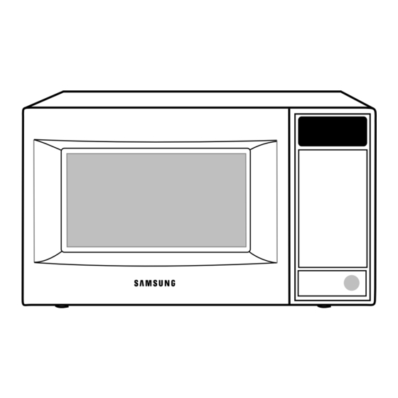
Page 6: Operating Instructions
Press to pause oven ro correct a mistake. Press to start cooking 3-2 Features & External Views Light Safety Interlock Holes Ventilation Holes Door Control Panel Door Latches Open Door Push Button Guide Roller Glass Tray 215mm 370mm 517mm 379mm Samsung Electronics... -
Page 7: Disassembly And Reassembly
4-2 Replacement of High Voltage Transformer 1. Discharge the high voltage capacitor. 2. Disconnect all the leads. 3. Remove the mounting bolts. 4. Reconnect the leads correctly and firmly. Samsung Electronics... -
Page 8: Replacement Of Door Assembly
¥ Insertion depth of the thin metal plate should be 0.5mm or less. 4-3-3 Removal of Key Door & Spring Door "E" Remove pin hinge from Door "E" Detach spring from Door "E" and key door. Key Door Spring Samsung Electronics... -
Page 9: Replacement Of Fuse/Drive Motor
7. When replacing the drive motor, be sure to remount it in the correct position with the Drive Motor Cover Base Plate coupler. 8. Connect all the leads to the drive motor. 9. Screw the drive motor cover to the base plate with a screw driver. Samsung Electronics... - Page 10 3. When installing new membrane key board, make sure that the surface of escutcheon base is cleaned sufficiently so that any problems (shorted contacts or uneven surface) can be avoided. Membrane Panel Samsung Electronics...
-
Page 11: Alignment And Adjustments
5-1 High Voltage Transformer 1. Remove connectors from the transformer terminals Filament Terminals and check continuity. 2. Normal resistance readings are as follows: Primary Terminals MODEL MW5490W W ± 10% Secondary 88.0 Filament Shows Continuity Primary 0.32W ± 10% (Room temperature = 20ûC) -
Page 12: High Voltage Capacitor
Door Open Door Closed procedures. ¥ Primary switch 5. Confirm that the gap between the switch ¥ Monitor switch (COM-NC) housing and the switch actuator is no more than ¥ Door Sensing S/W 0.5mm when door is closed. Samsung Electronics... - Page 13 NOTE 1: Variations or errors in the test procedure will cause a variance in the temperature rise. Additional power test should be made if temperature rise is marginal. NOTE 2: Output power in watts is computed by multiplying the temperature rise (step 5) by a factor of 91 times the of centigrade temperature. Samsung Electronics...
-
Page 14: Procedure For Measurement Of Microwave Energy Leakage
; CENTRAL SERVICE CENTER 5-12-2 At least once a year have the microwave energy survey meter checked for accuracy by its manufacturer. Samsung Electronics... -
Page 15: Troubleshooting
H.V.Transformer component test procedure and replace if it is H.V.Capacitor defective. H.V.Diode Magnetron 4. Open or loose wiring of power relay 5. Defective primary latch switch 6. Defective power relay or Ass'y PCB Replace PCB main. Samsung Electronics... - Page 16 Use plastic wrap or cover with a lid. Stir once or twice while cooking foods such as soup, cocoa, or milk. Noise from the turntable motor Noise may result from the motor. Replace turntable motor. when it starts to operate. Samsung Electronics...
-
Page 17: Exploded Views And Parts List
7. Exploded Views and Parts List 7-1 Exploded Views Samsung Electronics... -
Page 18: Main Parts List
ASSY-HVD;V2M6,PI9.0,0.05MT DE74-20015B TRAY-COOKING;GLASS,T6.0,PI318,1050G,MW5630T DE92-90189P ASSY-GUIDE ROLLER;MW5896W DE67-60081A COUPLER;PPS,-,-,-,3RD-1.0/1.3 DE61-50579A FOOT;PP,H8,PI15.8x16.1,-,BLK,3RD DE80-10001F BASE-PLATE;SGCC,T0.8,W345,L565,MW5896W DE31-10154A MOTOR-DRIVE;M2HJ49ZR02,ST-16,50/60HZ DE71-00015A COVER-CEILING;T0.3,W114.2,L121.5,-,CE2933 DE94-00146C ASSY CONTROL-BOX;120V60HZ,MW5490W,P/WHT MW5490W DE94-00146D ASSY CONTROL-BOX;120V60HZ,MW5491G,D/GRY MW5491G DE94-00145C ASSY DOOR;MW5490,P/WHT MW5490W DE94-00145D ASSY DOOR;MW5491G,D/GRY MW5491G DE39-20146B ASSY POWER CORD;125V13A,AWG16,1350,GRAY,MSP-36 DE63-90035L CUSHION-RUBBER;T3,W100,L190,-,MW5896W,BLK O/PANEL : Warning... -
Page 19: Door Parts List
SWITCH-MEMBRANE;PET,MW5490W,120V60HZ MW5490W DE34-00013F SWITCH-MEMBRANE;PET,MW5491G,120V60HZ, MW5491G DE72-70161A CONTROL-PANEL;ABS(VH-0800),PURE-WHT,MW5470W MW5490W DE72-70161B CONTROL-PANEL;ABS(VH0800),GRY,MW5471G MW5491G DE97-00047A ASSY PCB-MAIN;RA-W3LCD2-01,MW4590W DE93-30402M ASSY CONTROL-PANEL;MW5490W,P/WHT,3RD-1.0CU.FT,NEWGUARD MW5490W DE93-30402N ASSY CONTROL-PANEL;MW5491G,D/GRY,3RD-1.0CU.FT,NEWGUARD MW5491G DE64-00044A WINDOW-COVER HIDDEN;ABS(HR0370U),BLK,MW4390W,LCD-N/G DE67-40003E WINDOW-DISPLAY;SAN,-,-,-,CLEAR,MW5490W,BLK PRINT 7-5 Body Latch Parts List Ref. No. Parts No. Description/Specification Q'ty Remarks DE66-40001C LATCH-BODY;PP(FB53WH),-,39.2G,NTR,-,3RD-W MW5592W... -
Page 20: Standard Parts List
SCREW-A;2S-4X12,TOOTHED P-C-EA DE60-10082H SCREW-A;2S-4X12,TOOTHED PN/OUT DE60-10082H SCREW-A;2S-4X12,TOOTHED S-M-EA DE60-10098A SCREW-ASSY TAP TITE;PH,TC,M4X8,SWRCH18A,ZPC2,GLD,W M/DRIV DE60-10088A SCREW-TAP PH;PH,M3,L8,FEFZY,PLAIN DE60-10098A SCREW-ASSY TAP TITE;PH,TC,M4X8,SWRCH18A,ZPC2,GLD,W DE60-10012A SCREW-TAP TITE;TH,+,3,M4,L10,SWR10,ZPC2,TOOTH DE60-10098A SCREW-ASSY TAP TITE;PH,TC,M4X8,SWRCH18A,ZPC2,GLD,W M/DRIV DE60-10088A SCREW-TAP PH;PH,M3,L8,FEFZY,PLAIN DE60-10098A SCREW-ASSY TAP TITE;PH,TC,M4X8,SWRCH18A,ZPC2,GLD,W DE60-10012A SCREW-TAP TITE;TH,+,3,M4,L1,SWR1,ZPC2,TOOTH Samsung Electronics... - Page 21 8. P.C.B Diagrams 8-1 P.C.B Diagrams Samsung Electronics...
- Page 22 DE13-20009A IC;KA7533,DIP IC02 DE39-60001A WIRE-SO COPPER;PI0.6,SN,T,52MM,TAPING_WIRE J01,J02,J04,J05,J10,J11,J12 DE39-60001A WIRE-SO COPPER;PI0.6,SN,T,52MM,TAPING_WIRE J13,J14,J15,J16,J17 DE09-00031A IC-MCU;TMP87CH21AF-2454,MW4592W,8BIT IC01 3501-001050 RELAY-MINIATURE;24VDC,200mW,5A,1FormA,10mS,5mS RY02 3501-001062 RELAY-POWER;24VDC,523.2mW,16A,1FormA,15mS RY01 3708-000528 CONNECTOR-FPC/FC/PIC;13P,2.54mm,STRAIGHT,SN CN05 DE07-00002A LCD-DISPLAY;KXN31993DAN,67*26.5*2.85 LCD1 DE26-20149A TRANS-L.V;SLV-4270U,120V,60HZ,AC17V/7V LVT1 DE30-20016A BUZZER;CBE2220BA,STICK BUZ1 DE92-00022B ASSY PCB SUB;PIN IN,IC-LCD2-A,MASK(COB) IC01 Samsung Electronics...
-
Page 23: Schematic Diagrams
DOOR IS OPENED ASSY PCB BOARD MAGNETRON BLK BLU HIGH VOLTAGE DIODE TO CHASSIS PRIMARY SWITCH HIGH VOLTAGE CAPACITOR DOOR SENSING SWITCH MONITOR SWITCH BOTTOM CENTER SYMBOL COLOR ORANGE HIGH VOLTAGE WHITE TRANSFORMER BLACK BLUE BLU RED POWER RELAY Samsung Electronics...