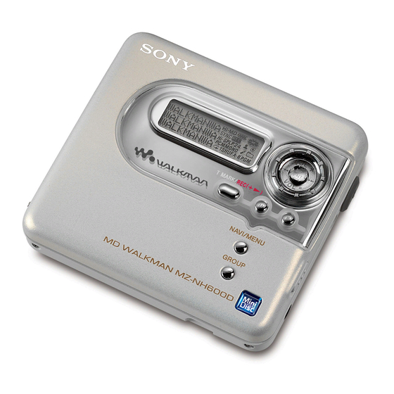
Sony MZ-NH600D Service Manual
Portable minidisc player
Hide thumbs
Also See for MZ-NH600D:
- Operating instructions manual (80 pages) ,
- Quick start (2 pages) ,
- Specifications (2 pages)
Table of Contents
Advertisement
SERVICE MANUAL
Ver 1.0 2004.05
US and foreign patents licensed from Dolby
Laboratories.
• SonicStage, MD Simple Burner, OpenMG, "Magic Gate", "MagicGate Memory Stick",
"Memory Stick", Hi-MD, Net MD, ATRAC, ATRAC3, ATRAC3plus and their logos are
trademarks of Sony Corporation.
• Microsoft, Windows, Windows NT and Windows Media are trademarks or registered
trademarks of Microsoft Corporation in the United States and /or other countries.
• IBM and PC/AT are registered trademarks of International Business Machines Corporation.
• Macintosh is a trademark of Apple Computer, Inc. in the United States and/or other countries.
• MMX and Pentium are trademarks or registered trademarks of Intel Corporation.
• All other trademarks and registered trademarks are trademarks or registered trademarks
of their respective holders.
Audio playing system
MiniDisc digital audio system
Laser diode properties
Material: GaAlAs
Wavelength: λ = 790 nm
Emission duration: continuous
Laser output: less than 44.6 µW
(This output is the value measured at a distance
of 200 mm from the lens surface on the optical
pick-up block with 7 mm aperture.)
Recording and playback time
When using HMD1G (1GB disc):
Maximum 34 hours in Hi-LP stereo
When using MDW-80 in Hi-MD mode:
Maximum 10 hours and 10 min. in Hi-LP
stereo
When using MDW-80 in MD mode:
Maximum 160 min. in monaural
Maximum 320 min. in LP4 stereo
Revolutions
380 rpm to 2,700 rpm (CLV)
Error correction
Hi-MD:
LDC (Long Distance Code)/BIS (Burst
Indicator Subcode)
MD:
ACIRC (Advanced Cross Interleave Reed
Solomon Code)
Sony Corporation
9-877-841-01
Personal Audio Company
2004E05-1
Published by Sony Engineering Corporation
© 2004.05
MZ-NH600D
Model Name Using Similar Mechanism
MD Mechanism Type
Optical Pick-up Mechanism Type
SPECIFICATIONS
Sampling frequency
44.1 kHz
Sampling rate converter
Input: 32 kHz/44.1 kHz/48 kHz
Coding
Hi-MD:
ATRAC3plus (Adaptive TRansform
Acoustic Coding 3 plus)
MD:
ATRAC
ATRAC3 − LP2/LP4
Modulation system
Hi-MD:
1-7RLL (Run Length Limited)/PRML
(Partial Response Maximum Likelihood)
MD:
EFM (Eight to Fourteen Modulation)
Frequency response
20 to 20,000 Hz ± 3 dB
Outputs
1)
i
: stereo mini-jack
Maximum output (DC)
Headphones:
5 mW + 5 mW (16 Ω)
Power requirements
One LR6 (size AA) alkaline battery (not
supplied)
PORTABLE MINIDISC PLAYER
US Model
Canadian Model
NEW
MT-MZNH900-181
ABX-U
Operating temperature
+5°C (+41°F) to +35°C (+95°F)
Dimensions
Approx. 83.6 × 28.9 × 77.0 mm (w/h/d)
× 1
× 3
3
3
1
(3
/
/
/
in.) (excluding projecting
8
16
8
parts and controls)
Mass
Approx. 99 g (3.5 oz) (the player only)
1)
Measured in accordance with JEITA.
Supplied accessories
Headphones (US)
Earphones (Canadian)
Dedicated USB Cable
CD-ROM (Sonic Stage Ver. 2.0/MD Simple
Burner Ver. 2.0)*
*Do not play a CD-ROM on an audio CD player.
– Continued on next page –
Advertisement
Table of Contents

Related Manuals for Sony MZ-NH600D


Summary of Contents for Sony MZ-NH600D
-
Page 1: Specifications
Power requirements One LR6 (size AA) alkaline battery (not ACIRC (Advanced Cross Interleave Reed supplied) – Continued on next page – Solomon Code) PORTABLE MINIDISC PLAYER Sony Corporation 9-877-841-01 Personal Audio Company 2004E05-1 Published by Sony Engineering Corporation © 2004.05... -
Page 2: Table Of Contents
20.0 hours 24.5 hours Notes on chip component replacement When using a new Sony LR6 (size AA) alkaline dry battery • Never reuse a disconnected chip component. (produced in Japan) Measured in accordance with the JEITA (Japan Electronics and Information •... -
Page 3: Servicing Notes
MZ-NH600D SECTION 1 SERVICING NOTES NOTES ON HANDLING THE OPTICAL PICK-UP Providing the required system environment BLOCK OR BASE UNIT System requirements The laser diode in the optical pick-up block may suffer electrostatic break-down because of the potential difference generated by the The following system environment is required in order to use the SonicStage Ver. -
Page 4: General
MZ-NH600D SECTION 2 This section is extracted from instruction manual. GENERAL Looking at controls The player A x (stop) • CANCEL button I 5-way control key USB cable connecting jack B OPEN switch K Battery compartment (at the bottom) C Display window... -
Page 5: Disassembly
MZ-NH600D SECTION 3 DISASSEMBLY • This set can be disassembled in the order shown below. 3-1. DISASSEMBLY FLOW Note 1: The process described in can be performed in any order. Note 2: Without completing the process described in , the next process can not be performed. -
Page 6: Case (Lower) Section
MZ-NH600D 3-2. CASE (LOWER) SECTION 1 two screws (M1.4) 1 two screws (M1.4) 2 Remove the case (lower) section in the direction of the arrow. 3-3. MAIN BOARD 2 LCD module flexible board (CN471) 3 motor flexible board (CN701) 8 OP flexible board... -
Page 7: Case (Upper) Section
MZ-NH600D 3-4. CASE (UPPER) SECTION 1 LCD module flexible boaed (CN471) 7 case (upper) section 6 boss 3 herical torsion spring (L) 4 two step screws 2 Open the case (upper) section. 3-5. MECHANISM DECK SECTION (MT-MZNH900-181), MD STANDARD PIN... -
Page 8: Set Chassis Assy
MZ-NH600D 3-6. SET CHASSIS ASSY 5 two screws 1 torsion coil spring (R) 2 extension spring (R) 7 set chassis assy 6 battery case 3 compression coil spring (open) 4 open slider 3-7. GEAR (BSA), GEAR (SB) 1 self tap screw 2 thrust retainer spring 3 washer (0.8-2.5) -
Page 9: Op Service Assy
MZ-NH600D 3-8. OP SERVICE ASSY 3 Remove lead screw block assy. 4 OP service assy 2 rack spring 1 screw (M1.4) 3-9. DC MOTOR SSM18D/C-NP (SPINDLE) (M701), DC MOTOR (SLED) (M702), DC MOTOR UNIT (OVER WRITE HEAD UP/DOWN) (M703) 3 two screws (M1.4) -
Page 10: Holder Assy
MZ-NH600D 3-10. HOLDER ASSY 4 Remove the holder assy to the direction of the arrow A . 2 boss 3 Open the holder assy. 1 boss... -
Page 11: Diagrams
MZ-NH600D SECTION 4 DIAGRAMS 4-1. BLOCK DIAGRAM – MD SERVO Section – OVER WRITE HEAD DRIVE IC601 (1/2) HR601 (Page 12) OVER WRITE OVER 69 HBB HEAD DRIVE WRITE 78 HB Q601, 602 HEAD 70 HBA EFM_CLK LATCH M703 OUTA... -
Page 12: Block Diagram -Power Supply Section
MZ-NH600D 4-2. BLOCK DIAGRAM – POWER SUPPLY Section – (Page 11) SDO0 DATA SDO0 SCK0 SCK0 (Page 11) VRMC RMC KEY (Page 11) XWK3 XWK4 WAKE UP SWITCH 5 XWK1 Q902 XWK2 S892 S892 HALF_LOCK_SW/ HALF YUZU_SLEEP SLEEP OPEN_SW LOCK... - Page 13 MZ-NH600D • Note For Printed Wiring Boards and Schematic Diagrams • Waveforms Note on Printed Wiring Board: Note on Schematic Diagram: IC501 8 (RFO) • X : parts extracted from the component side. • All capacitors are in µF unless otherwise noted. (p: pF) •...
-
Page 14: Printed Wiring Board -Main Section (1/2)
MZ-NH600D 4-3. PRINTED WIRING BOARD – MAIN Section (1/2) – : Uses unleaded solder. • Semiconductor Location Ref. No. Location D151 D440 D457 S894-1 S894 D458 PROTECT D605 DETECT D606 S894-2 Hi-MD D607 PROTECT D608 DETECT D614 D615 D616 D902... -
Page 15: Printed Wiring Boards -Main Section (2/2)
MZ-NH600D 4-4. PRINTED WIRING BOARDS – MAIN Section (2/2) – : Uses unleaded solder. • Semiconductor Location Ref. No. Location MAIN BOARD (CONDUCTOR SIDE) D251 D352 D471 S892 D601 (HALF LOCK) M702 D602 (SLED) D603 D604 XRST BOARD D609 M703... -
Page 16: Schematic Diagram -Main Section (1/8)
MZ-NH600D • See page 24 for IC Block Diagram. 4-5. SCHEMATIC DIAGRAM – MAIN Section (1/8) – (1/8) XRST_MTR_DRV XRST_MTR_DRV SLD_CON_W C714 SLD_CON_W SLD_CON_V SLD_CON_V SLD_CON_U SLD_CON_U SLD_PWM L701 L702 SLD_PWM SLD_MON_U SLD_MON_U SLD_MON_V SLD_MON_V SLD_MON_W SLD_MON_W SLD_CON_W R706 2.2k R707 2.2k... -
Page 17: Schematic Diagram -Main Section (2/8)
MZ-NH600D • See page 24 for IC Block Diagrams. 4-6. SCHEMATIC DIAGRAM – MAIN Section (2/8) – (2/8) XCS_REC_DRV SUSPEND C673 SUSPEND REG_DACVREFH USB_HOLD USB_HOLD RECP RECP C668 EFM_CLK D610 EFM_CLK MA2Z748001S0 C669 C643 VOLTAGE DETECT XCS_REC_DRV IC606 +1.2V REGULATOR... -
Page 18: Schematic Diagram -Main Section (3/8)
MZ-NH600D • See page 13 for Waveforms. • See page 24 for IC Block Diagram. 4-7. SCHEMATIC DIAGRAM – MAIN Section (3/8) – (Page 16) (3/8) C553 C554 6.3V C523 C524 C530 0.01 (Page 17) +3V REGULATOR R505 L503 IC502 C561 10µH... -
Page 19: Schematic Diagram -Main Section (4/8)
MZ-NH600D 4-8. SCHEMATIC DIAGRAM – MAIN Section (4/8) – (Page 17) (4/8) (Page 23) Q451 RTQ035P02TR R463 R464 100k C453 0.047 Q451,452 USB ON/OFF SWITCH R467 Q452 XP4601-TXE DRY BATTERY C423 C424 SIZE"AA" C452 R462 D458 R466 220k MA8056-L-TX 2.2M (IEC DESIGNATION R6) 1PC. -
Page 20: Schematic Diagram -Main Section (5/8)
MZ-NH600D • See page 24 for IC Block Diagram. 4-9. SCHEMATIC DIAGRAM – MAIN Section (5/8) – (Page 17) (5/8) (Page 18) L903 10µH C927 C915 100p L9001 6.3V 10µH C922 C923 C958 C928 C929 R954 R955 100p 1000p 470k 2.2k... -
Page 21: Schematic Diagram -Main Section (6/8)
MZ-NH600D • See page 24 for IC Block Diagram. 4-10. SCHEMATIC DIAGRAM – MAIN Section (6/8) – (Page 17) (6/8) C354 R352 220k Q353 SI1410EDH-T1 R356 100k Q351 2SC4738F-Y/GR (TPL3) REFERENCE AOUTL AOUTL VOLTAGE SWITCH AOUTR C351 R353 AOUTR XHP_STBY... -
Page 22: Schematic Diagram -Main Section (7/8)
MZ-NH600D • See page 24 for IC Block Diagram. 4-11. SCHEMATIC DIAGRAM – MAIN Section (7/8) – (7/8) R478 4.7k R476 R477 4.7k 4.7k R489 CN471 R486 DVDD R471 JOG_B XRST2 JOG_B R472 JOG_A JOG_A SET_KEY_2 SET_KEY_2 SET_KEY_1 SET_KEY_1 R473... -
Page 23: Schematic Diagram -Main Section (8/8)
MZ-NH600D • See page 13 for Waveforms. • See page 27 for IC Pin Function Description. 4-12. SCHEMATIC DIAGRAM – MAIN Section (8/8) – (8/8) POEN_CLOSE_SW WK_DET SCK0 R876 R868 Q803 R827 2SC4738F-Y/GR (Page 22) R880 (TPL3) R861 R813 R842... - Page 24 MZ-NH600D • IC Block Diagrams IC601 SC901585VAR2 IC352 TA2131FLG (EL) BEEP VREF V REF CHARGE PUMP LPF1 NC A12 MT TC 56 LATCH VCC1 EFM BOTTOM 55 XWKO LVDT WAKE PRE DRIVER BST NF1 HOLD OUT HOLD CONTROL BST1 VBUS...
- Page 25 MZ-NH600D IC701 BD6607KN 62 61 48 WI2 STANDBY DECODER DECODER PRE DRIVE PRE DRIVE PGNDW1 47 PGNDW2 46 WO2 45 ST2 VMVW1 44 VMVW2 43 VO2 42 VO2 PGNDUV1 41 PGNDUV2 40 UO2 39 UO2 VMU1 38 VMU2 VMR1 37 VMR2...
- Page 26 MZ-NH600D IC901 SC901584EPR2 36 35 RESET 2 SERIAL RST2 PASS POWER STEP REGULATOR 3 SWITCH 2 UP-DOWN REGC2 DRIVER RST2 MUTING REG2G VREF REF2 SERIAL BUFFER REGO2 PASS REGULATOR 2 REGI2 32 DTC2 REGC1 VREF RST1 SERIAL REF2 REGO1 PASS...
- Page 27 MZ-NH600D • IC Pin Function Description IC801 CXD2681-221GG (SYSTEM CONTROLLER, DIGITAL SIGNAL PROCESSOR) Pin No. Pin Name Description DVDD1_0 — Power supply terminal DVSS1_0 — Ground terminal DVDD1_1 — Power supply terminal DVSS1_1 — Ground terminal DVDD1_2 — Power supply terminal DVSS1_2 —...
- Page 28 MZ-NH600D Pin No. Pin Name Description DAVDD — Power supply terminal (for D/A converter) DVDD25LPF — Power supply terminal (for D/A converter) DAVSS — Ground terminal (for D/A converter) OSCVDD — Power supply terminal (for 22 MHz OSC) USBOSCVDD —...
- Page 29 MZ-NH600D Pin No. Pin Name Description Phase comparison output terminal for the playback EFM system master PLL FILI Filter input terminal for the playback EFM system master PLL FILO Filter output terminal for the playback EFM system master PLL CLTV...
- Page 30 MZ-NH600D Pin No. Pin Name Description VREFL Reference voltage terminal connected to the capacitor (for the built-in D/A converter L-CH) AOUTL Built-in D/A converter L-CH signal output AOUTR Built-in D/A converter R-CH signal output VREFR Reference voltage terminal connected to the capacitor (for the built-in D/A converter R-CH)
- Page 31 MZ-NH600D Pin No. Pin Name Description Serial data input from the EEPROM Serial data output to the EEPROM SCK0 Serial clock output to the EEPROM XGUM_ON Rechargeable battery detection signal terminal Not used BEEP Beep sound control signal output to the headphone amplifier...
- Page 32 MZ-NH600D Pin No. Pin Name Description XRST_MTR Reset signal output to the motor driver _DRV XCS_NV Chip select signal output to the EEPROM CHG_PWM Charge current or voltage control signal output terminal Not used IAMP_CAL Offset signal output of current sense amplifier Not used —...
- Page 33 MZ-NH600D Pin No. Pin Name Description SCS4 Chip select signal output for ATRAC3 plus encoder communication Not used HI_Z_SLD Standby signal output terminal for the sled motor HI_Z_SPDL Standby signal output terminal for the spindle motor 291 to SET_CODE0 to...
-
Page 34: Exploded Views
MZ-NH600D SECTION 5 EXPLODED VIEWS NOTE: • -XX and -X mean standardized parts, so they • Items marked “*” are not stocked since they The components identified by mark 0 or dotted line with mark 0 are may have some difference from the original are seldom required for routine service. -
Page 35: Case (Upper) Section
MZ-NH600D 5-2. CASE (UPPER) SECTION not supplied not supplied Ref. No. Part No. Description Remark Ref. No. Part No. Description Remark 3-264-154-01 BADGE (HI-MD) 3-266-219-01 KNOB (5DIR) (N FNT) X-2022-631-1 CASE (UPPER) (S) (SV) ASSY 1-805-515-11 LCD MODULE 3-266-189-01 OPEN LOCKER... -
Page 36: Chassis Section
MZ-NH600D 5-3. CHASSIS SECTION mechanism deck section MAIN board (including the XRST board) Ref. No. Part No. Description Remark Ref. No. Part No. Description Remark 3-266-202-01 SPRING (OPEN), COMPRESSION COIL 3-238-876-04 SCREW (M1.4), TOOTHED LOCK 3-266-197-01 OPEN SLIDER 3-266-204-01 TERMINAL (+), BATTERY 3-266-196-01 CASE, BATTERY 3-266-203-01 TERMINAL (–), BATTERY... -
Page 37: Mechanism Deck Section (Mt-Mznh900-181)
MZ-NH600D 5-4. MECHANISM DECK SECTION (MT-MZNH900-181) not supplied HR601 (over write head) M702 M703 (including HR601 (over write head) ) M701 The components identified by Les composants identifiés par une mark 0 or dotted line with marque 0 sont critiques pour la mark 0 are critical for safety. -
Page 38: Electrical Parts List
MZ-NH600D SECTION 8 ELECTRICAL PARTS LIST MAIN NOTE: • Items marked “*” are not stocked since they • Due to standardization, replacements in the The components identified by mark 0 or dotted line with mark 0 are parts list may be different from the parts are seldom required for routine service. - Page 39 MZ-NH600D MAIN Ref. No. Part No. Description Remark Ref. No. Part No. Description Remark C559 1-164-941-11 CERAMIC CHIP 0.0047uF 10% C674 1-112-010-91 CAP, CHIP MICA 33PF C560 1-125-777-11 CERAMIC CHIP 0.1uF C675 1-164-943-11 CERAMIC CHIP 0.01uF C676 1-164-937-11 CERAMIC CHIP 0.001uF...
- Page 40 MZ-NH600D MAIN Ref. No. Part No. Description Remark Ref. No. Part No. Description Remark C903 1-164-943-11 CERAMIC CHIP 0.01uF D615 6-500-909-01 DIODE MA22D1700LS0 C906 1-100-352-91 CERAMIC CHIP D616 6-500-909-01 DIODE MA22D1700LS0 D801 8-719-072-27 DIODE MA2Z748001S0 C908 1-164-943-11 CERAMIC CHIP 0.01uF...
- Page 41 MZ-NH600D MAIN Ref. No. Part No. Description Remark Ref. No. Part No. Description Remark L506 1-400-397-11 INDUCTOR 10uH R151 1-218-965-11 RES-CHIP 1/16W L507 1-400-397-11 INDUCTOR 10uH (CND) L601 1-414-398-11 INDUCTOR 10uH R152 1-218-957-11 RES-CHIP 2.2K 1/16W L603 1-414-398-11 INDUCTOR 10uH...
- Page 42 MZ-NH600D MAIN Ref. No. Part No. Description Remark Ref. No. Part No. Description Remark R485 1-218-985-11 RES-CHIP 470K 1/16W R648 1-245-456-21 METAL CHIP 1/5W R486 1-218-990-11 SHORT CHIP R649 1-245-456-21 METAL CHIP 1/5W R650 1-216-793-11 METAL CHIP 1/10W R489 1-218-990-11 SHORT CHIP...
- Page 43 MZ-NH600D MAIN XRST Ref. No. Part No. Description Remark Ref. No. Part No. Description Remark R841 1-208-635-11 METAL CHIP 0.5% 1/16W R954 1-218-985-11 RES-CHIP 470K 1/16W R842 1-218-973-11 RES-CHIP 1/16W R955 1-218-957-11 RES-CHIP 2.2K 1/16W R958 1-218-973-11 RES-CHIP 1/16W R843 1-218-957-11 RES-CHIP 2.2K...
- Page 44 MZ-NH600D Ref. No. Part No. Description Remark Ref. No. Part No. Description Remark MISCELLANEOUS ************** 0 163 X-2021-785-1 OP SERVICE ASSY (ABX-U) (including HR601(OVER WRITE HEAD)) M701 8-835-782-12 MOTOR, DC SSM18D/C-NP (SPINDLE) M702 1-787-143-11 MOTOR, DC (SLED) M703 1-477-519-21 MOTOR UNIT, DC...
- Page 45 MZ-NH600D MEMO...
- Page 46 MZ-NH600D REVISION HISTORY Clicking the version allows you to jump to the revised page. Also, clicking the version at the upper right on the revised page allows you to jump to the next revised page. Ver. Date Description of Revision...