
Related Manuals for Andrew TYPE 100


Summary of Contents for Andrew TYPE 100
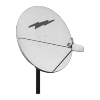
- Page 1 Assembly Instructions 90cm, 1.0m & 1.2m SMC Antenna System with Az/El Cap Mount TYPE 900 - 90cm TYPE 100 - 1.0m TYPE 120 - 1.2m SMC ANTENNA WITH AZ/EL CAP MOUNT Andrew Corporation Andre w Corporation Customer Support Center...
- Page 2 REV. service. ANDREW shall repair or replace defective equipment, at no charge, or at its option, refund the purchase price, if the equipment is returned to ANDREW not more than twelve (12) months after shipment. Removal or reinstallation of equipment and its transportation shall not be at the cost of ANDREW except ANDREW shall return repaired or replaced equipment freight prepaid.
-
Page 3: Site Selection
(60 lbs). Be prepared to safely handle these forces at unexpected moments. Do not attempt to assemble, move or mount a dish on windy days or serious, even fatal accidents may occur. ANDREW is not responsible or liable for dam- age or injury resulting from antenna installations. - Page 4 GROUND POLE INSTALLATION 2 ” O.D. x 72” LONG 2 " O.D. DEEP PIER FROST LINE FOUNDATIONS FOUNDATIONS 1" to 2" SLOPE FOR WATER RUN OFF GRADE OVAL END MIN. BELOW FROST LINE DIA. PIER FOUNDATIONS WIND VEL. DIM “d” CONC VOL.
- Page 5 PARTS AND HARDWARE LISTING 8.04 REF 11.80 REF FIG. 4.0 - AZ/EL CAP MOUNT ITEM DESCRIPTION MOUNT ASSY AZ-EL CAP 2 ”-3” MAST CLAMP HALF 2 ”-3” AZ-EL HOUSING AZ-EL CAP MOUNT BOLT, M8 x 130mm HEX HEAD NUT, SWIVEL, SPECIAL M8 BOLT, M8 x 20mm, CRG BOLT, M8 x 30mm, CRG WASHER,...
-
Page 6: Assembly And Installation
ASSEMBLY AND INSTALLATION The AZ/EL Cap Mount can be installed on a 2 ” or 3” O.D. ground tube, roof, or wall mount depending on model. The appropriate mount should be assembled and in place before installing the AZ/EL cap. As the AZ/EL cap mount is factory preassembled, there is no assembly required for the mount. - Page 7 ELEVATION CHART " L" IS THE DIFFERENCE BETWEEN THE EARTH STATION ANTENNA SITE LONGITUDE AND THE SATELLITE LONGITUDE 5° 10° 15° 20° 25° 30° 35° 40° 45° 50° 55° 60° 65° 70° 75° EARTH STATION LATITUDE IN DEGREES NORTH OR SOUTH OF EQUATOR CHART 2 95°...
-
Page 8: Antenna Alignment Procedure
ANTENNA ALIGNMENT PROCEDURE Alignment with the satellite is obtained by setting polar- ization, elevation and azimuth. Charts 1, 2 & 3 are to FEED determine the values for your earth station antenna site. ASSEMBLY “∆L” is the difference between the earth station antenna site longitude and the satellite longitude.