Table of Contents
Advertisement
Quick Links
Installation, Operation and Maintenance
Type ES49( )
4.9-Meter ESA
The installation, maintenance, or removal of antenna systems requires qualified, experienced personnel. Andrew installa-
tion instructions have been written for such personnel. Antenna systems should be inspected by qualified personnel to
verify proper installation, maintenance and condition of equipment.
Andrew Corporation disclaims any liability or responsibility for the results of improper or unsafe installation and mainte-
nance practices.
All designs, specifications, and availabilities of products and services presented in this manual are subject to change
without notice.
Andrew Corporation
10500 West 153rd Street
Orland Park, IL U.S.A. 60462
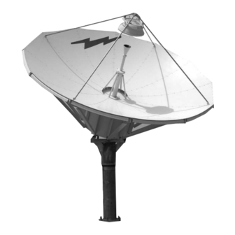
4.9-Meter Earth Station Antenna
Telephone: 708-349-3300
FAX (U.S.A.): 1-800-349-5444
Internet: http://www.andrew.com
Notice
Customer Service, 24 hours: U.S.A. • Canada • Mexico: 1-800-255-1479
U.K.: 0800 250055 • Republic of Ireland: 1 800 535358
Other Europe: +44 1592 782612
Bulletin OM49
Revision G
12/03
Copyright © 2003 by Andrew Corporation
Advertisement
Table of Contents

Related Manuals for Andrew 4.9-Meter ESA


Summary of Contents for Andrew 4.9-Meter ESA
- Page 1 Antenna systems should be inspected by qualified personnel to verify proper installation, maintenance and condition of equipment. Andrew Corporation disclaims any liability or responsibility for the results of improper or unsafe installation and mainte- nance practices.
-
Page 2: Table Of Contents
Table of Contents Introduction Introduction............... . 3 Proprietary Data . -
Page 3: Introduction
4.9-Meter Earth Station Antenna Introduction Like all Andrew earth station antennas, the 4.9-Meter Earth Station Antenna provides high gain and exceptional pattern characteristics. The electrical performance and excep- tional versatility provides the ability to configure the antenna with your choice of linearly- or circularly-polarized 2-port or 4-port combining network. -
Page 4: Proprietary Data
The technical data contained herein is proprietary to Andrew Corporation. It is intended for use in operation and maintenance of Andrew supplied equipment. This data shall not be disclosed or duplicated in whole or in part without express written consent of Andrew Corporation. -
Page 5: How To Use This Manual
Describes the controls, functions, and general operating procedures required for proper operation of the 4.9-Meter Andrew Earth Station Antenna. • Preventive Describes preventive maintenance procedures that are required to Maintenance maintain proper functional operation of your new Andrew Earth Station Antenna. How to Use This Manual... -
Page 6: Getting Started
Should it be expected that winds will exceed 125 mph, it is recommended that Andrew antennas be steered to specific azimuth and elevation orientations (refer to #8) to minimize wind forces upon the structure and there- by increase the probability of survival. -
Page 7: Recommended Tools
Andrew supplies all appropriate hardware/parts required for the installation of your 4.9- Tools Meter Earth Station Antenna. All tools necessary for the installation process should be provided by the installation crew. Andrew recommends the following tools to be used for a proper installation of the 4.9-Meter Earth Station Antenna. Tool... -
Page 8: Parts Verification
Parts Verification Andrew Corporation thoroughly inspects and carefully packs all equipment before ship- ment. If you find that there are missing components, please notify Andrew Corporation immediately by contacting the Customer Service Center (refer to page 4). Reporting If you find that there was damage caused to the equipment during the shipping process, Equipment Loss or a claim should be filed with the carrier. -
Page 9: Returning Equipment
Returning Andrew Corporation tries to ensure that all items arrive safe and in working order. Equipment Occasionally, despite these efforts, equipment is received which is not in working condi- tion. When this occurs, and it is necessary to return the equipment to Andrew... -
Page 10: Installation Procedures
Installation Procedures Overview This section provides installation procedures for the 4.9-Meter Andrew Earth Station Antenna. The installation procedures include instructions on the following antenna com- ponents: • • Reflector/Enclosure Reflector-to-Mount Assembly • • Mount Subreflector Foundation Before beginning the installation process on the ground mount assembly, ensure that Preparation the foundation has been prepared. - Page 11 Foundation Preparation Figure 1b Installation Procedures...
-
Page 12: Foundation Notes
Foundation Notes 1. Remove all burrs and sharp edges. 2. Dimensions apply before plating. 3. Interpret drawing per ANSI Y14.5M-1982. 4. Dimensions are shown in feet and inches. Dimensions in brackets [ ] are in millimeters. 5. A tolerance of ±1/8" [3] applies to all anchor bolt layout dimensions. 6. -
Page 13: A325 Tensioning
A325 Tensioning During the installation process, there are several references to the A325 hardware ten- sioning procedure. The A325 hardware must be properly tensioned to avoid slippage between bolted surfaces under high loads. Slippage can cause the corresponding assembly to move, causing antenna misalignment. When designated, the A325 hard- ware should be tightened according to the following tensioning procedure. -
Page 14: Reflector/Backstructure Assembly
Reflector/Back Use of A325 hardware eliminates slippage between mating surfaces under high loading Structure conditions as well as the need for future retightening. Refer to the A325 tensioning pro- Assembly cedure in preceding installation text. CAUTION: Adhere to any special instructions sten- ciled on crate relative to crate opening, contents removal and/or personnel safety. - Page 15 Step 2 Loosely attach 302511 Ribs to 302648 Short Struts as shown in Figure 4. Note: Do not fully tighten hardware at this time. Support end of rib until 302509 Long Strut is installed. 1/2” 1/2” ID 1” Lock 302511 Washer Flat (9974-64)
- Page 16 302511 Reference Drawing 240272 1/2” ID x 5/8” ID x 1” OD 1/2” 1-5/16” OD Flat Lock Flat 5/8” ID x 1-5/16” OD Washer Washer Washer Flat Washer (9997-65) (9974-64) 5/8” x 1/2” (9997-236) (9997-236) Shoulder 1/2” Hex Nut Bolt (9999-61) (9858-36) 5/8”...
- Page 17 Step 6 Attach the reflector panels (with skirts) by placing them on the ribs and sliding them inward carefully guiding them until the rib and panel holes align. Place the seam hard- ware in the fourth hole from the outboard edge on both sides of the panel to set panel bay spacing, finger tighten only.
-
Page 18: Subreflector Support Brackets
Subreflector Support Brackets Step 1 Attach four 206278 lifting tabs across the second and third pairs of reflector seam holes from reflector center as shown in Figure 8. Note: Do not fully tighten lifting tab hardware at this time. Reference Drawing 240272 Note: To be removed after reflec- tor installation on ground mount. - Page 19 Step 2 Attach the four 302518 Subreflector Support Brackets at the 15th (outer most) reflector panel hole position from reflector center on ribs 2, 5, 8, and 11 as shown in Figure 9. Note: Do not fully tighten subreflector support bracket hardware at this time. 302518 1/4 x 1-1/4”...
-
Page 20: Rotating Tube Assembly
Rotating Tube Assembly Note: Applicable feed installation drawings are included with each feed system. Step 1 Install 302356 Rotating Tube Assembly as shown in Figure 10. Ensure 302507 Support Struts attach to ribs 2, 5, 8 and 11 as shown. Note: Ensure all support struts are attached to same side of reflector rib and rotating tube mounting tab. -
Page 21: Polarization Drive Installation
Polarization Drive Installation Step 1 Attach the Polarization Drive Assembly as shown in Figure 11. Measure and cut chain to proper length. Step 2 Attach chain to coupling link on each end with supplied connecting link. Step 3 Pull pillow blocks and sprocket assembly back until chain is tight. Tighten bolts holding pillow blocks in place. -
Page 22: Subreflector Assembly
Subreflector Assembly Step 1 Loosely attach four 302767 Subreflector Struts together with the four 302769 Apex Angle Brackets as shown in Figure 12. Note: The struts are not connected to the reflector at this time. 3/8” 3/8 x 2-1/4” Reference Drawing 240272 Hex Head Flat Washer 302769... - Page 23 Step 3 Install 302514 Subreflector Assembly to the 302768 Subreflector Ring Support Brackets as shown in Figure 14. Securely tighten all subreflector assembly hardware at this time. Reference Drawing 240272 3/8 x 1” Hex Head Capscrew (9963-115) 3/8” Flat Washer Centered (9997-145) Adjustment Stud...
-
Page 24: Pedestal Ground Mount Assembly
Pedestal Ground The pedestal mount is an elevation-over-azimuth mount optimized for geostationary satellite Mount Assembly applications. The mount enables continuous elevation adjustment from 0 to 90°. The azimuth axis has 360° of travel with 40° (±20°) of continuous travel at each adjustment posi- tion. - Page 25 Step 3 Refer to Figure 16. Using the 6 foot nylon choker under the stinger arm, and the 3 foot chok- er around the elevation pivot tube, lower the pedestal into position over the anchor bolts. Note: Hex nuts and flatwashers supplied with 302689 anchor bolt kit. Reference Drawing 240299 3 Ft.
- Page 26 (9997-229) 302677 Pedestal Assembly Split PVC Drain Required Anchor Bolts, if Cavity is Grouted Nuts and Washers (Part of Andrew 302689) Foundation Reference Drawing 240299 Figure 17 (Manual Mount) Note: Jacks are not installed until after the pedestal is securely Level Pedestal attached to the foundation.
- Page 27 Step 6 Refer to Figure 17B. Attach Az/El Jack Screw Assemblies and pedestal jack arm to (Motorized Mount pedestal assembly as shown. Only) Reference Drawing 240349 9997-202 Flatwasher 45980-28 3/4” x 2.5” Lg Bolt/Nut Assembly 45980-28 3/4” x 2-1/2” Lg Bolt/Nut Assembly and (2) 9997-202 Flatwashers (4 Places)
-
Page 28: Reflector To Ground Mount Assembly
The ground mount assembly is now completed with the necessary essentials. All ground mount options have separate instructional bulletins located in the parts kit that contain the option. The next step in the installation process is the reflector assembly. Proceed to the next step to begin installation of the reflector. - Page 29 Step 2 Gently lower the reflector assembly into position and attach to elevation pivot lugs using 3/4” hardware as shown in Figure 19. Note: Refer to A325 Tensioning Procedure on page 13. • Use indicated hardware and securely tighten. Note: After attaching the reflector, the crane may now be removed while the antenna is in the zenith position.
-
Page 30: Subreflector Installation And Adjustment
Subreflector IMPORTANT Installation and Adjustment Failure to conform to the following alignment procedures may result in non-com- pliance to antenna performance specification. Step 1 Carefully raise the completed subreflector assembly into place with the reflector in the zenith position. Attach the subreflector assembly to the reflector as shown in Figure 20. Note: All INTELSAT Type Approved antennas do not require further subreflector adjust- ment after performing Steps 2 thru 8. - Page 31 Step 2 Reference the appropriate feed installation drawing and install the feed system assembly. Note: The feed installation instructions are packaged as part of the feed system kit. Step 3 Adjust the height of the subreflector with the 302752-( ) Subreflector Setting Rod. Rest the square end of the setting rod on top of the first panel seam screw.
- Page 32 Reference Drawing 240272 Subreflector Centering Adjustment Hardware Threaded Rod (3 Places) Adjustment Location (3 Places) Figure 22 Step 6 Recheck subreflector centering and height settings. Step 7 Remove and store 206278 lifting tabs. Replace panel seam hardware at lifting tab loca- tions.
-
Page 33: Operation
Operation Overview There are several procedures that may be used to properly acquire the satellite. Andrew recommends that a spectrum analyzer be used. The following procedures provide explanation as to how to use the spectrum analyzer. Acquiring A While viewing the spectrum analyzer screen, a signal as shown in Figure 4-1 will proba- bly be observed. - Page 34 The following steps provide the procedure for acquiring a satellite. Step 1 Begin by obtaining the correct Az/El pointing data for the satellite of interest based on specific calculations for this particular site. Step 2 Using an inclinometer placed on the enclosure drum surface, position the antenna to the specified elevation angle.
- Page 35 Step 7 Move the antenna in azimuth to obtain a null, then move ± in elevation to obtain a large peak signal. If not, move the antenna in the opposite azimuth direction through the peak and again move ± in elevation to obtain a large peak signal. If a larger peak is not found, you were on the main lobe.
- Page 36 Step 10 With all 24 transponder signals of approximately equal amplitude appearing on the spectrum analyzer screen determine the specific antenna system and satellite parame- ters. Rotate the feed assembly as required until the appropriate (odd or even) transpon- der signals are maximized. Figure 4-4: Maximizing Odd Transponders Figure 4-5: Optimum Polarization Setting Operation...
-
Page 37: Subreflector Adjustment
Subreflector After the satellite has been acquired and testing has taken place with the spectrum ana- Adjustment lyzer, the subreflector may need to be adjusted to maximize optimum performance of your antenna. The following procedures should be followed if a subreflector adjustment is required to maximize optimum performance. -
Page 38: Overview
Preventive Maintenance Overview This section contains periodic preventive maintenance instructions for the 4.9-Meter Earth Station Antenna. Included in this section are inspection and preventive mainte- nance procedures including cleaning and lubrication, painting, and an operational volt- age/current checkout procedure deemed within the capabilities of the average station technician. -
Page 39: Mechanical Parts
Mechanical Parts Clean mechanical parts by first removing dust, dirt, and other loose contaminants with a scraper, stiff brush (bristle or wire in the case of rust or other corrosion), or cloth or com- pressed air at 25 to 40 psi. Any accumulated imbedded dirt, corrosion, grease, or oil deposits that require further cleaning may be removed with a bristle or wire brush and a cleaning solvent such as trichlorethylene or equal. -
Page 40: Preventive Maintenance
• Visually inspect the feed window for dirt and the feed, feed supports, feed window, and reflector for distortion, foreign object damage and environmental deterioration due to ice and snow, dust, rain, hail, and high winds, etc. which may cause electrical compo- nent and/or structural deformation. -
Page 41: Preservation Of Component Parts
Preservation of When preserving the component parts, refer to the following paragraphs in this section. Component Parts Aluminum Parts Remove all loose paint and corrosion by scraping, wire brushing, or using steel wool. If using steel wool near the feed window, make sure that none remains on the feed horn window. - Page 42 any protective caps and clean off each lubrication fitting prior to injecting fresh grease. The elevation and azimuth jackscrew assemblies are equipped with a grease fitting and corresponding pipe plug on opposite sides of the jack housing. Remove the appropriate pipe plug and fill with with grease until lubricant seeps from the pipe plug opening.