Chapters
Table of Contents

Related Manuals for LG GC260W


Summary of Contents for LG GC260W
-
Page 1: Video Cassette
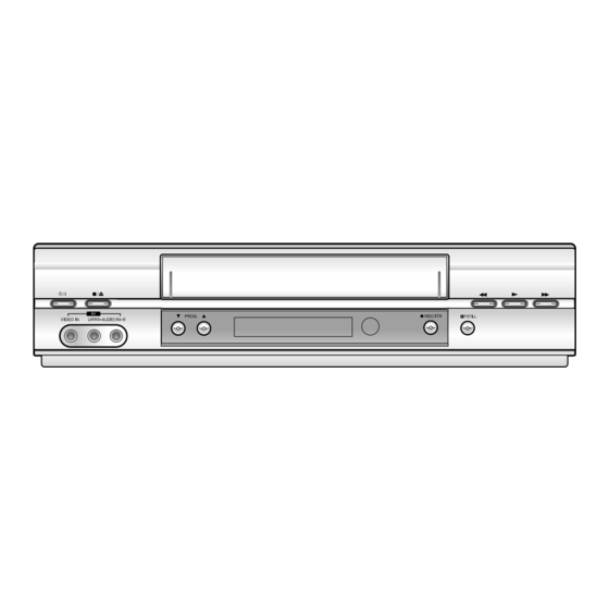
VIDEO CASSETTE RECORDER SERVICE MANUAL SERVICE MANUAL MODELS : GC260W/GC480W/GC990W (GC260W1/GC480W1/GC990W1) CAUTION BEFORE SERVICING THE UNIT, READ THE “SAFETY PRECAUTIONS” IN THIS MANUAL. PLAY GC260W GC480W GC990W... -
Page 3: Table Of Contents
TABLE OF CONTENTS SECTION 1 CIRCUIT DIAGRAMS ....3-30 1. Power Circuit Diagram ....3-30 SUMMARY 2. -
Page 4: Key To Abbreviations
SECTION1 SUMMARY KEY TO ABBREVIATIONS :Alternating Current :Low Pass Filter :Automatic Color Control :Maximum ACSS :Automatic Channel Setting System :Modulator :Adjust MECHA.CTL :Mechanism Control :Audio Erase :Microphone :Automatic Frequency Control :Minimum :Automatic Fine Tuning :Mixer, Mixing :Automatic Gain Control M.M. :Monostable, Multivibrator A.H.SW :Audio Head Switch... -
Page 5: Product Safety Servicing Guidelines For Video Products
PRODUCT SAFETY SERVICING GUIDELINES FOR VIDEO PRODUCTS CAUTION : DO NOT ATTEMPT TO MODIFY THIS PRODUCT IN ANY WAY, SUBJECT : X-RADIATION NEVER PERFORM CUSTOMIZED INSTALLATIONS WITHOUT MANUFAC- 1. BE SURE PROCEDURES AND INSTRUCTIONS TO ALL SERVICE PER- TURER’S APPROVAL. UNAUTHORIZED MODIFICATIONS WILL NOT ONLY SONNEL COVER THE SUBJECT OF X-RADIATION. -
Page 6: Servicing Precautions
SERVICING PRECAUTIONS CAUTION : Before servicing the VCR covered by this service Electrostatically Sensitive (ES) Devices data and its supplements and addends, read and follow the Some semiconductor (solid state) devices can be damaged SAFETY PRECAUTIONS. NOTE : if unforeseen circum- easily by static electricity. -
Page 7: Protection
PROPOSAL FOR APPLYING SHORT PROTECTION • The Contents of Examination As all the IC that is applied to VCR is controlled by IIC, mutual communication, if Vcc of IC is short or open with detecting ‘Acknowledge’ data of the specific IC according to each power(5V, 5VT) µ-COM gets unable to detect ‘ACK’... -
Page 8: Service Notice On Replacing Eeprom
SERVICE NOTICE ON REPLACING EEPROM In case that defective EEPROM of PAL models is replaced, to operate these sets from the initial state MP KEY must be repaired as well before delivering to the customer. If MP KEY isn’t repaired the setting of RF OUT channel or LANGUAGE might be different from that for cus- tormer’s country. -
Page 9: Ic Setting
WR : OK I : EXIT MOVE : F G (Setup upon BOM depending on OPT1~OPT3 model) EDIT : DE • Since an initial remote control is set to LG for LG model, appropriately set optional data using the MASKROM : R00 cursor Up/Down key. -
Page 10: Specifications
SPECIFICATIONS General Power 110-240V~, 50/60Hz Power consumption Approx. 12 Watts Video Head System Double azimuth 4 heads, helical scanning (EC-530W) Rotary 2 heads, helical scanning (EC-330W) Tape speed PAL: 23.39 mm/sec (SP mode) 11.69 mm/sec (LP mode) NTSC: 33.35 mm/sec (SP mode) 11.12 mm/sec (LP mode) Tape Format Tape width 12.7mm (0.5 inch) Max. -
Page 11: Service Method
SECTION2 CABINET & MAIN FRAME SERVICE METHOD (1) Disassembly Flow (2) Re-assembly Flow for service like Fig. 2-1 Top Case LED C.B.A Bottom Cover Main C.B.A Front Panel Housing & Deck Assembly Housing & Deck (3) To check and replace Electrical parts Assembly Disassemble the unit according to No.1) Disassembly Flow. -
Page 12: Exploded Views
EXPLODED VIEWS 1. Cabinet and Main Frame Section NOTE) Refer to “SECTION 5 REPLACEMENT PARTS LIST” in order to look for the part number of each part. _ OPTIONAL PARTS... -
Page 13: Packing Accessory Section
2.Packing Accessory Section NOTE) Refer to “SECTION REPLACEMENT PARTS LIST NOTE) in order to look for the part number of each part. OPTIONAL PARTS CABLE, COAXIAL (Optional parts) PLUG ASS'Y 1WAY (Optional parts) CABLE ASS'Y RF PLUG ASS'Y 2WAY (Optional parts) INSTRUCTION MANUAL BATTERY PACKING (LF) -
Page 14: Electrical Adjustment Points Arrangement
SECTION 3 ELECTRICAL ELECTRICAL ADJUSTMENT POINTS ARRANGEMENT : Measurement point : Adjustment point 3/4 CH SWITCH A/V JACK SMPS AVCP Hi-Fi DECK CNT. TUNER & MODULATOR SYSTEM U-COM DRIVE CLK/DOT DISP BOARD(L) BOARD(R) -
Page 15: Electrical Adjustment Procedures
ELECTRICAL ADJUSTMENT PROCEDURES 1. Servo Adjustment 1) PG Adjustment • Test Equipment a) OSCILLOSCOPE b) PAL TEST TAPE (VHS SP) c) JIG REMOCON (AUTO PG SETTING) • Adjustment And Specification MODE MEASUREMENT POINT ADJUSTMENT POINT SPECIFICATION V.Out PLAY 6.5 ± 0.5H H/SW(W714, W715) •... - Page 16 ELECTRICAL ADJUSTMENT PROCEDURES • WAVEFORM H/SW 6.5H(416us) Composite VIDEO • Attension and Reference a) The PG checking must do when RF Level is Maximum and SERVO system is Locking (MTR MODE) b) V.H/SW Level is 2Vpp.
-
Page 17: Electrical Troubleshooting Guide
ELECTRICAL TROUBLESHOOTING GUIDE 1. Power Circuit(SMPS) (1) No 5.3VA. No 5.3VA. Replace the F101 Is the F101 normal? (Use the same Fuse). Is the BD101 normal? Replace the BD101. Is the R101 normal? Replace the R101. Does the oscillation waveform appear at Is Vcc(about 13~15V) permittable at the the IC101 Pin 7? IC101 Pin 3? - Page 18 7. Power Circuit(SMPS) (2) No 12VA.(Capstan) No 12VA. Does 5.3VA work normally? Check whether 5.3VA is out of order. Is the D109 normal? Replace the D109. Check 12VA Line of the Main PCB short. (3) No 12V (Hi-Fi, Buffer) No 12VA. Is Vcc(about 12V) put into the Q152(E)? Replace the Peripheral Circuitry of ZD152.
- Page 19 7. Power Circuit(SMPS) (4) No 5V No 5V. Is 5.3VA put into the Q155(Q157) collector? Is the Q156 Base “H”? Check the µ-com Control. Is about 4.7V put into the Check the Q156 Q155(Q157) Base? whether it works normally. Check or Replace the Q155(Q157).
-
Page 20: Servo Circuit
2. Servo Circuit Unstable Video in PB Mode. Does the on screen noise level change periodically? Do CTL pulses appear at IC501 pin 97? Does the CFG divide Is the height of the CTL waveform appear at IC501 Head adjusted correctly? pin 87? Do the CTL pulses move Adjust the CTL Head. - Page 21 Drum Motor stopped. Does 12V appear at PMC01 PIN8? Does Drum CTL signal appear at PMC01 Check Power. PIN12? Does Drum PWM appear at IC501 Check Connector and Drum Motor Ass’y. Pin 76? Check the Components and foil Pattern Do DPG/FG Pulses appear at PMC01 between IC501 Pin 76 and PMC01 Pin 11? Pin 12 for shorts.
- Page 22 Capstan Motor Stopped. Does 12VA appear at PMC01 Pin 2? Does 2.8V appear at PMC01 Pin 9? Check Power. Check Connector and Capstan Does PWM wave appear at IC501 Motor Ass’y. Pin 77? Check the Components and foil Patterns Does the CFG signal appear at PMC01 Connected between IC501 Pin 77 and Pin 1? PMC01 Pin 9 for shorts.
-
Page 23: System & Front Panel Circuit
3. System & Front Panel Circuit Auto stop. Does SW30 waveform appear at IC501 Pin 18? Do Take-up reel pulses Check the Drum Motor appear at IC501 Pin 80? Signal. Does 5.3V appear at Change IC501. RS501. Replace the Take-Up Reel Photocoupler on Main Check the Power. - Page 24 Cassette tape loading is unstable. Is REG 12V applied to PMC01 Pin 8? Is High signal applied to IC501 Pin 58 Check the power. When inserting the CST? Is 5.3V applied to R544? Does Low signal occur form IC501 Pin 60 Check the CST SW and Check the power.
- Page 25 Non working functon buttons. Is the voltage of IC501 Pin 99, 5V? Does LED CLOCK, LED DOT display change when a function button is Check the power. pressed? Replace the defective Switch. Replace IC501. (Function SW) LED CLOCK, LED DOT doesn’t work. Is 5V applied to IC501 Pins 37 and Check the power circuit.
-
Page 26: Y/C Circuit
4. Y/C CIRCUIT (1) No Video in EE Mode, No Video in EE Mode Check the Video Input Does the Video signal Jack. appear at the IC301 Pin 48? (Line In Jack) Is 5V applied to the IC301 Check the 5.2V, 5.4VA Pins 18, 24, 42, 55, 72, 91? Line. - Page 27 3. Y/C CIRCUIT (2) When the Y(Luminance) signal doesn’t appear on the screen in PB Mode, Is 5.2VT, 5.4VA applied to the Check the line of the 5.2V Line. (Power Circuit) IC301 Pins 24, 42, 55, 72, 91? Is the I C Bus siganl applied Refer to ‘SYSTEM I C BUS...
- Page 28 3. Y/C CIRCUIT (3) When the C(Color) signal doesn’t appear on the screen in PB Mode, Is 5.2V/5.3VA applied to the Check the line of the 5.2V/ 5.3VA Line. (Power Circuit) IC301 Pins 24, 42, 55, 72, 91. Is the Color Rotary signal Check the Color Rotary applied to the IC301 Circuit.
- Page 29 3. Y/C CIRCUIT (4) When the Video signal doesn’t appear on the screen in REC Mode, Is the EE signal normal? Check EE Mode. Is 5.2V/5.3VA applied to the Check the line of the 5.2V/ IC301 Pins 24,42,55,72,91? 5.3VA Line.(Power Circuit) Does PB Mdoe operate Check PB Mode.
-
Page 30: Tuner/If Circuit
5. Tuner/IF circuit (1) No picture on the TV screen No picture on the TV screen Does the Video signal at Is +30V applied to Check 34V line. the TU701 Pin19? TU701 Pin 17? Is +5.2V applied to Check 5.2V line. TU701 Pin 4? Does the Clock signal Check the liC Clock... - Page 31 (2) No sound (Mono Model) No sound Check the Vcc of IC301 Pin 18. Check 5.2V power. Check the Tuner Audio signal Chekc the signal flow from TU701 at IC301 Pin 13. Pin15 to IC301 Pin 13. Check the Audio signal at IC301 Pin 11. Replace IC301.
- Page 32 (3) No sound (Hi-Fi Model) No sound Check the Vcc of IC751 Pins 1, 19, 33. Check 5V power. Check the Tuner SiF signal at IC751 Pin 2. Check the Tuner Audio of TU701 Pin 21. Check the oscillator of IC751 Pins 5, 6. Replace X751.
-
Page 33: Hi-Fi Circuit
6. Hi-Fi Circuit (Hi-Fi Model) Hi-Fi Playback. Check the Vcc of No sound IC801.(Pins 34, 40) Check the Hi-Fi Selection Check power. Switch and the Tape quality. Is the RF Envelope at Is the Head switching signal Check IC501 Pin 19. IC801 Pin 44 over 2Vp-p? IC802 Pin 41 O.K? (Audio head switch 25) - Page 34 Hi-Fi REC. It is impossible to record and playback Hi-Fi Audio signal. Check Vcc of IC801. (Pins 34,40) Check IC801 Pin 42(Data),Pin 43(CLOCK). Check Power. Do Audio signals appear at IC801 Check ports of µ-COM. Pins 16, 17? Do FM Audio signals appear at IC801 Check Audio input signal of IC801 Pin 36? Pins 2, 3(TU.A.), 6, 7(Scart 1)
-
Page 35: Block Diagrams
BLOCK DIAGRAMS 1. Power Block Diagram T101 BD101 R101 TRANSFORMER RECTIFIER Q152, ZD152, TO Hi-Fi SNUBBER & SMOOTHING R153, C155 BLOCK (D109, C120, C103 L104,C121) (D102,R104, F. µ-com Q161 C105,C106) HSR "H" RECTIFIER & SMOOTHING R163 24V S/W TO CAPSTAN M (D110, C123) Q159,R166,R167 24/12VA... - Page 36 2. Tu/IF, NICAM & A2 Block Diagram IC751 MSP3417 MSP3407 A.OUT TU33V V.OUT '04. 03. 03 3-24 3-25...
-
Page 37: Y/C Block Diagram
3. Y/C Block Diagram 4. Hi-Fi Block Diagram (PB MODE) 60dB AMP PB FM MAIN SUB LPF DE EMP Y/C MIX Y-LPF PB FM EQ FM OEM V.ENV IC301 LA71750M Y-Delay MAIN C-Delay C LPF CONV (1H/2H) (REC MODE) 68 67 V.IN2 S1 CLIP EMPHA... -
Page 38: System Block Diagram
5. System Block Diagram TO/FROM DECK TO/FROM AVCP 5.3VA MODE S/W MS501 9 18 95 94 87 12 59 60 CV IN I-Limit MODE S1 MODE S1 OSD 'H' MODE S2 REC 'H' MODE S2 MODE S3 MODE S4 MODE S3 DISPLAY MODE S4 S clk... -
Page 39: Circuit Diagrams
CIRCUIT DIAGRAMS 1. Power Circuit Diagram Power is dead. No power. D109, C120 are defective. BD101, R101 are defective. D102 is defective. No 12VA and 12V. No 5.3VA and 5.1V. D106 is defective. Switching dead. IC101 is defective. Power dead. F101 is defective. -
Page 40: Tuner, Nicam, A2 Circuit Diagram
2. Tuner, NICAM, A2 Circuit Diagram EE MODE(VIDEO) TU MODE (AUDIO) 3-32 3-33... -
Page 41: A/V Circuit Diagram
3. A/V Circuit Diagram IC301 Pin70 is defective. PB COLOR Signal disappear. D301 or IC301 Pin 80 REC is defective. IC301 Pin 84 is defective. Audio Tracking is failed. IC301 Pin 69, 68 are defective. PB and Recording is failed. (IC301 doesn’t operate.) 8 13 X301 is defective. -
Page 42: System Circuit Diagram
4. System Circuit Diagram • Reset is defect. • Set dead. IC504 is defective. 3 4 9 Clock setting will not operate. Remote control is Pulse coil not Receive. OSD will not operate. X501 is defective. RC501 is defective. L511, R598, C595, C596 are defective. -
Page 43: Hi-Fi Circuit Diagram
5. Hi-Fi Circuit Diagram IC801 42, 43 Pins are defective. All Audio is not appear. RF Hi-Fi V.out NORMAL AUDIO V.in 3-38 3-39... -
Page 44: Waveform
WAVEFORM _ C301 Osc oscope Wave orm _ C501 Wave orm pho ographs @ @ @ @ @ @ @ @ @ @ h e ? @ @ ? h e ? @ @ @ @ @ @ @ @ @ @ @ @ @ @ @ @ @ @ @ @ @ @ @ @ @ @ @ @ @ @ @ @ @ @ @ @ @ @ @ @ @ @ @ @ @ @ @ @ @ @ @ @ @ h e ? @ @ ? h e ? @ ( M e ? I ' @ @ @ e @ @ @ @ @ @ @ @ @ @ @ @ @ @ @ @ @ @ @ @ @ @ @ @ @ @ @ @ @ @ g ? @ @ @ @ @ @ @ h e W 2 @ 6 X ? f W 2 @ 6 X ? e ? @ @ @ f ? @ @ @ e ? W 2 @ @ @ 6 X g ? @ @ ? @ @ f ? W 2 @ @ 6 X ? e ? @ @ ? ? W 2 @ g ? @ H ? W 2 6 K V @ @ 5 e @ @ @ @ @ @ @ @ @ @ @ @ @ @ @ @ @ @ @ @ @ @ @ @ @ @ @ @ @ @ g ? @ @ @ @ @ @ @ h ? W &... -
Page 45: Circuit Voltage Chart
• CIRCUIT VOLTAGE CHART MODE MODE MODE MODE MODE MODE MODE PIN NO. PIN NO. PIN NO. PIN NO. PIN NO. PIN NO. PIN NO. I C 2 0 2 3.35 3.35 3.35 5.17 5.16 5.11 PULSE PULSE PULSE 2.76 2.82 2.64 5.16... - Page 46 EE Mode PB Mode REC Mode Tran- Emitter Collector Base sistor Q151 4.55 5.24 5.34 4.54 5.24 4.55 5.24 Q501 Q152 5.31 4.52 5.22 5.31 4.52 5.22 4.51 5.22 Q503 4.43 4.43 Q154 32.99 32.34 32.97 33.53 32.89 33.5 33.76 33.12 33.72 Q506...
-
Page 47: Printed Circuit Board Diagrams
PRINTED CIRCUIT BOARD DIAGRAMS 1. MAIN P.C.Board (TOP VIEW) LOCATION GUIDE (Solder Side) 3-46 3-47... -
Page 48: Main P.c.board (Bottom View)
2. MAIN P.C.Board (BOTTOM VIEW) LOCATION GUIDE 3-48 3-49... -
Page 49: Key (Left) P.c.board
3. KEY (LEFT) P.C.Board ( GC260W/GC480W ONLY ) ( GC990W ONLY ) LOCATION GUIDE LOCATION GUIDE (Solder Side) (Solder Side) 3-50 3-51... -
Page 51: Mechanism Parts
SECTION 4 MECHANISM (D-37) CONTENTS POSITION DRAWING OF DECK DECK MECHANISM ADJUSTMENT MECHANISM PARTS • Fixtures and tools for service ....4-12 1. Check of Mechanism Assembly Mode ..4-13 • Top View............4-1 2. Previous Preparation for • Bottom View ..........4-1 Deck Adjustment ........4-14 3. -
Page 52: Position Drawing Of Deck Mechanism Parts
POSITION DRAWING OF DECK MECHANISM PARTS • Top View Order Of Dis- Ref. Posi assembled Part Fixing Type Draw- tion Parts firstly ings Disassembled 1 Drum Assembly 3 screws 2 Plate Top 2 hooks 3 Holder Assembly CST 6 chasses 4 Gear Assembly Rack F/L 1 hook 2,3,4... -
Page 53: Disassembly And Assembly Of Deck Mechanism
DISASSEMBLY AND ASSEMBLY OF DECK MECHANISM Drum Assembly Cable Flat (S1) (S1) (S1) Cap, FPC Holder FPC Fig. A-1 Cautions in assembly of FPC 1. Disassembly of Drum Assembly (Figure A-1) 1) Separate cable flat from the Drum FPC and the Capstan Motor. -
Page 54: Plate Top Disassembly
DISASSEMBLY AND ASSEMBLY OF DECK MECHANISM Plate Top (Fig. A-2-1) (B') Holder Assembly CST (Fig. A-2-2) Arm Assembly F/L (Fig. A-2-5) Lever Assembly S/W (Fig. A-2-6) (H4) Opener Door (Fig. A-2-4) (H3) Gear Assembly Rack F/L (Fig. A-2-3) Fig. A-2... - Page 55 DISASSEMBLY AND ASSEMBLY OF DECK MECHANISM 2. Disassembly of Plate Top (Fig. A-2-1) 4. Disassembly of Gear Assembly Rack F/L (Fig. A-2-3) 1) Separate the right part while leaning back the (B) part of 1) Separate the hook (H3) while leaning ahead the hook (3) the plate top toward the arrow direction.
-
Page 56: Motor Assembly L/D
DISASSEMBLY AND ASSEMBLY OF DECK MECHANISM Arm Assembly Cleaner (Fig. A-3-3) (H5) Gear Wheel (Fig. A-3-2) Base Assembly A/C Head Motor Assembly L/D (S5) (Fig. A-3-5) (Fig. A-3-1) Head F/E (C1) (Fig. A-3-4) (S4) Fig. A-3 8. Motor Assembly L/D (Fig. A-3-1) 10. -
Page 57: Brake Assembly T
DISASSEMBLY AND ASSEMBLY OF DECK MECHANISM Arm Assembly Tension (Fig. A-4-2) (H7) Reel T (Fig. A-4-3) Reel S (Fig. A-4-3) Spring Tension Brake Assembly T Spring Tension (Fig. A-4-1) (H8) (H6) Fig. A-4 13. Brake Assembly T (Fig. A-4-1) 15. Reel S/Reel T (Fig. A-4-3) 1) Release the spring tension from the lever spring hook 1) Disassemble the reel S/ reel T while holding it up (com- (H6). -
Page 58: Base Assembly P4
DISASSEMBLY AND ASSEMBLY OF DECK MECHANISM Opener Lid (Fig. A-5-2) Arm Assembly Pinch (Fig. A-5-3) Base Assembly P4 (Fig. A-5-1) (H9) Arm T/up (Fig. A-5-4) Chassis Fig. A-5 16. Base Assembly P4 (Fig. A-5-1) 18. Arm Assembly Pinch (Fig. A-5-3) 1) Release the (A) part of the base assembly P4 from the 1) Hold the arm assembly pinch up. -
Page 59: Supporter, Capstan
DISASSEMBLY AND ASSEMBLY OF DECK MECHANISM Suppoter Capstan (Fig. A-6-1) Belt Capstan (Fig. A-6-2) Motor Capstan (Fig. A-6-3) Washer(W1) Clutch Assembly D37 (Fig. A-6-5) (L1) (L1) Lever F/R (Fig. A-6-4) Chassis (S6) Fig. A-6 20. Supporter, Capstan (Fig. A-6-1) 22. Lever F/R (Fig. A-6-4) 1) Turn the supporter and Capstan by 90 deg. -
Page 60: Gear Drive/Gear Cam
DISASSEMBLY AND ASSEMBLY OF DECK MECHANISM (H10) (H11) Gear Sector Gear Cam (Fig. A-7-3) (Fig. A-7-2) (W2) Washer (W2) Brake Assembly Capstan Gear Cam Hole(B) (Fig. A-7-4) Plate Slider (L2) Gear Drive (Fig. A-7-5) (Fig. A-7-1) Gear Drive Hole(A) Lever Tension (Fig. -
Page 61: Gear Assembly P2/Gear Assembly P3
DECK MECHANISM DISASSEMBLY Gear assembly P2 Hole Gear assembly P3 Hole Gear Assembly P3 (Fig. A-8-2) Gear Assembly P2 (Fig. A-8-1) (H13) (H12) Lever Tension Boss Plate slider Hole(B) (H14) Base Loading (Fig. A-8-5) Chassis Base Assembly P3 (Fig. A-8-4) Base Assembly P2 (Fig. -
Page 62: Base Tension
DISASSEMBLY AND ASSEMBLY OF DECK MECHANISM Base Tension (Fig. A-9-1) Arm Assembly Idler Jog (Fig. A-9-2) Chassis Fig. A-9 34. Base Tension (Fig. A-9-1) 35. Arm assembly Idler Jog (Fig. A-9-2) 1) Release the (A) part of the base tension from the 1) Push both (B), (C) parts in Fig. -
Page 63: Deck Mechanism Adjustment
DECK MECHANISM ADJUSTMENT • Fixtures and Tools for Service 1. Cassette Torque Meter 2. Alignment tape 3. Torque gauge SRK-VHT-303(Not SVC part) Part No NTSC:DTN-0001 600g.Cm ATG Part No:D00-D006 PAL:DTN-0002 Part No:D00-D002 4. Torque gauge adaptor 5. Post height adjusting driver 6. - Page 64 DECK MECHANISM ADJUSTMENT 1. Mechanism Assembly Mode Check Purpose of adjustment : To make tools normally operate by positioning tools accurately. Fixtures and tools used VCR (VCP) status Checking Position • Eject Mode • Blank Tape (empty tape) • Mechanism and Mode Switch (with cassette withdrawn) 1) Turn the VCR on and take the tape out by pressing the 4) Undo the screw fixing the deck and the main frame, and...
-
Page 65: Previous Preparation For Deck Adjustment
DECK MECHANISM ADJUSTMENT 2. Previous Preparation for Deck Adjustment (Preparation to load the VCR (VCP) with cassette tape not inserted) 1) Take the power cord from the consent. If doing so, proceeding to the stop mode is done. In this 2) Separate the top cover and the plate assembly top. -
Page 66: Prior Adjustment
DECK MECHANISM ADJUSTMENT 4. Guide Roller Height Adjustment Purpose of adjustment : To ensure that the bottom surface of the tape can travel along with the tape lead line of the lower drum by constantly and adjusting and maintaining the height of the tape. 4-1. -
Page 67: Prior Adjustment
DECK MECHANISM ADJUSTMENT 5. Audio/Control (A/C) Head Adjustment Purpose of adjustment : To ensure that audio and control signals can be recorded and played according to the contract tract by constantly maintaining distance between tape and head, and tape tension between the P3 post and the P4 post. -
Page 68: Fine Adjustment (Azimuth Adjustment)
DECK MECHANISM ADJUSTMENT 5-2. Tape Path Check between Pinch Roller and travel it stably to ensure there is no crumbling or fold- ing of the tape. Take up Guide (Check in the Rev Mode) 1) Check the tape pass status between the pinch roller and 2) Check there is folding of the tape at the bottom or top the take-up guide.(Check there is crumpling of the tape of the take-up guide in cutting-off the REV mode... -
Page 69: Adjustment Of Drum Assembly (Video Heads)
DECK MECHANISM ADJUSTMENT 7. Adjustment after Drum Assembly (Video Heads) Purpose of adjustment : To adjust and stabilize the height change, X-distance change, etc depending on the guide roller after assembling the drum. Fixtures and tools used Connection position VCR (VCP) status Adjustment position •... -
Page 70: Removal Of Foreign Materials
PROTECTION, MAINTENANCE AND CHECK OF VIDEO FUNCTION 1. Checking Points prior to Repair Following abnormal phenomena may be repaired by removal of foreign materials and oil supply. Check oiling is required at the checking set or cleaning status is complete. Determine that necessity of checking and repair the set exists after checking the using period of the set together with the user. - Page 71 PROTECTION, MAINTENANCE AND CHECK OF VIDEO FUNCTION 2. Essential Check and Repair 4. Tools for Check and Repair Recording density of the video is far higher than the audio. (1) Grease: Floil G-3114 (KANTO) or equivalent grease Therefore video parts are very precise so as to allow only (Green) error of 1/1000mm or so in order to maintain compatibility (2) Grease: Kanto G-754, PL-433 (Yellow)
-
Page 72: Grease Application
PROTECTION, MAINTENANCE AND CHECK OF VIDEO FUNCTION 5-2) Grease Applications (2) Regular Grease Application Apply grease to the designated application position (1) Grease Application Method every 500 hour. Apply grease by using a cloth swab or brush. Care must be exercised so that excess quantity should not be used. - Page 73 PROTECTION, MAINTENANCE AND CHECK OF VIDEO FUNCTION Lever, F/R, Base, Tension GEAR AY, P2 & P3 PL-433 LEVER, F/R BASE, TENSION Clutch Contact Part (PL-433, Yellow) Tension Arm Party Hinge Part (PL-433, Yellow) 4-22...
-
Page 74: Deck Mechanism
MECHANISM TROUBLESHOOTING GUIDE 1.Deck Mechanism No Auto Rewind operates. Is output of the end sensor “H”? “H”: 3.5V or less “L”: 0.7V –1V or less Is the end sensor Vcc applied at Check the Syscon power supply. Replace the end sensor. Is voltage at both ends of the Replace the LED. - Page 75 MECHANISM TROUBLESHOOTING GUIDE Auto Stop operates. (PLAY/CUE/REV) Check the assembly mode. Check the spring pinch. Does the pinch roller attached to the Capstan shaft turn in opera- Is output of the DFG, DPG Replace the drum motor. tion of the Play/Cue/Rev. normal? Does the T/UP or the supply Check the Servo, Syscon.
- Page 76 MECHANISM TROUBLESHOOTING GUIDE No tape winding is done in play. Is the pinch roller attached to the Check the assembly mode? Capstan shaft in operation of play? Does the T/up reel operate? Is the Capstan belt hung? Hang the Capstan belt. Check the clutch and the idler Does the Capstan motor turn? assembly.
-
Page 77: Front Loading Mechanism
MECHANISM TROUBLESHOOTING GUIDE 2. Front Loading Mechanism No cassette insert is done. Does the lever assembly Is the lever assembly switch Add or replace the lever switch operate? spring normal? assembly switches spring. Does the CST IN switch Replace the F/L switch. operate normally? Is the Vcc of the main P.C.B assembly? - Page 78 MECHANISM TROUBLESHOOTING GUIDE No safe adherence of tape is done. Is cassette insert done? Does the opener lid operate? Replace the opener lid. Does the gear rack F/L operate? Replace the gear rack F/L. Does the opener door operate? Check the assembly status of the Does the arm assembly F/L operate? opener door.
-
Page 79: Exploded Views
EXPLODED VIEWS 1. Front Loading Mechanism Section 4-28... -
Page 80: Moving Mechanism Section(1)
EXPLODED VIEWS 2. Moving Mechanism Section (1) OPTIONAL PART 4-29... -
Page 81: Moving Mechanism Section(2)
EXPLODED VIEWS 3. Moving Mechanism Section (2) 4-30... -
Page 83: Replacement Parts List
PAL RF 1.2M + 2WAY Y/W 1.2M FR 6850R-PBA2J CABLE,COAXIAL 2 WAY COAXIAL YELLOW_WHITE DT *** REMOTE CONTROLLER 6711R1P073B REMOTE CONTROLLER ASSEMBLY V1 GC981NP2 NA5HLL LG W/O SHOW *** FRAMEL ASSEMBLY *** 3211R-V007E FRAME ASSEMBLY V6 MAIN 60HR 86570B "A" 3210R-V010E FRAME V6 MAIN MOLD 60HR 86570B "A"... - Page 84 S AL LOCA. NO. PART NO. DESCRIPTION SPECIFICATION REMARKS 4261R-0040A ARM ASSEMBLY DECK/MECHA TENSION - D37 3041R-M037A BASE ASSEMBLY P2 -D37 3041R-M038A BASE ASSEMBLY P3 - D37 3041R-M039A BASE ASSEMBLY P4 - D37 5870R-0007A OPENER DECK/MECHA LID OTHER - D37 3041R-M036A BASE ASSEMBLY A/C HEAD (ALPS) - D37...
- Page 85 S AL LOCA. NO. PART NO. DESCRIPTION SPECIFICATION REMARKS 4970R-0163A SPRING COIL D35S SWITCH 1MPC0301499 SCREW MACHINE,PAN HEAD D3.0 L4.0 SWRCH18A/FZY 1MEC0302018 PAN HEAD MACHINE SCREW S/W + D 3.0 L 6.0 MSWR3/FZY 1SZZR-0032B SCREW,DRAWING + 1 D2.6 L5.0 SWRCH18A/FZY TAP 1APF0262218 SCREW TAP TITE(B),PAN HEAD D2.6 L6.8 MSWR3/FZY...
- Page 86 S AL LOCA. NO. PART NO. DESCRIPTION SPECIFICATION REMARKS C305 0CH1103K512 CAPA,CHIP CERAMIC M/L H.D F/S 0.0100UF 50V K B 1608 R/TP C306 0CH1102K512 CAPACITOR,FIXED CERAMIC(TEMP.C 1000PF 50V 10% B(5YP) 1608 R/T C307 0CE1054K638 CAPACITOR,ELECTROLYTIC 1.0M SRA/SS50V M FM5 TP(5) C308 0CQ1532K409 CAPACITOR,FIXED FILM...
- Page 87 S AL LOCA. NO. PART NO. DESCRIPTION SPECIFICATION REMARKS C364 0CH4680K412 CAPACITOR,FIXED CERAMIC(HIGH D 68PF 50V 5% NP0 1608 R/TP C368 0CH1102K512 CAPACITOR,FIXED CERAMIC(TEMP.C 1000PF 50V 10% B(5YP) 1608 R/T C370 0CQ8224K409 CAPACITOR,FIXED FILM 0.0082UF TE 50V 5% PE TP5 C372 0CH1104K942 CAPACITOR,CHIP[CERAMIC M/L HD...
- Page 88 S AL LOCA. NO. PART NO. DESCRIPTION SPECIFICATION REMARKS C588 0CH1102K512 CAPACITOR,FIXED CERAMIC(TEMP.C 1000PF 50V 10% B(5YP) 1608 R/T C589 0CH4221K412 CAPACITOR,CHIP[CERAMIC M/L TC 220P 50V J COG 1.6X0.8 R/TP C590 0CE1054K638 CAPACITOR,ELECTROLYTIC 1.0M SRA/SS50V M FM5 TP(5) C591 0CH1102K512 CAPACITOR,FIXED CERAMIC(TEMP.C 1000PF 50V 10% B(5YP) 1608 R/T C592...
- Page 89 S AL LOCA. NO. PART NO. DESCRIPTION SPECIFICATION REMARKS D701 0DD133009AA DIODE,SWITCHING 1SS133 DETECT,SW TP D702 0DD133009AA DIODE,SWITCHING 1SS133 DETECT,SW TP ES501 4931R-0078C HOLDER ASSEMBLY VCR DECK/MECHA END(S) ES502 4931R-0078C HOLDER ASSEMBLY VCR DECK/MECHA END(S) F101 0FS1601B51D FUSE,SLOW BLOW 1600MA 250 V 5.2X20 CY/GL KS/J F101 585-011T FUSE,SLOW BLOW...
- Page 90 S AL LOCA. NO. PART NO. DESCRIPTION SPECIFICATION REMARKS LED501 6301R3U002D LED ASSEMBLY ELF347GWB/S285 EVERLIGHT UNIVE LED501 6301R2U002D LED ASSY TOF-3462AGE-B OASIS UNIVERSAL MS501 6600JR3002C SWITCH,MODE MMS01180ZMBO MIC 5VDC 1MA D37 PMC01 6630R-BE01L CONNECTOR (CIRC),BOARD TO BOAR JE612-12 JAE EUN 12P 2.0MM Q152 0TR534409AA TRANSISTOR...
- Page 91 S AL LOCA. NO. PART NO. DESCRIPTION SPECIFICATION REMARKS R126 0RD6800F608 RESISTOR,FIXED CARBON FILM 680 OHM 1/6 W 5% TA26 R153 0RH4701C622 RESISTOR,METAL GLAZED(CHIP) 4.7K OHM 1 / 16 W 1608 5.00% D R154 0RH1001C622 RESISTOR,METAL GLAZED(CHIP) 1K OHM 1 / 16 W 1608 5.00% D R155 0RH1802C622 RESISTOR,METAL GLAZED(CHIP)
- Page 92 S AL LOCA. NO. PART NO. DESCRIPTION SPECIFICATION REMARKS R355 0RH4702C622 RESISTOR,METAL GLAZED(CHIP) 47K OHM 1 / 16 W 1608 5.00% D R356 0RH4701C622 RESISTOR,METAL GLAZED(CHIP) 4.7K OHM 1 / 16 W 1608 5.00% D R359 0RH4702C622 RESISTOR,METAL GLAZED(CHIP) 47K OHM 1 / 16 W 1608 5.00% D R360 0RH4701C622 RESISTOR,METAL GLAZED(CHIP)
- Page 93 S AL LOCA. NO. PART NO. DESCRIPTION SPECIFICATION REMARKS R575 0RH4701C622 RESISTOR,METAL GLAZED(CHIP) 4.7K OHM 1 / 16 W 1608 5.00% D R576 0RH4701C622 RESISTOR,METAL GLAZED(CHIP) 4.7K OHM 1 / 16 W 1608 5.00% D R577 0RH4701C622 RESISTOR,METAL GLAZED(CHIP) 4.7K OHM 1 / 16 W 1608 5.00% D R578 0RH4701C622 RESISTOR,METAL GLAZED(CHIP)
- Page 94 THVV951BAA POSTECH DC 12 V 5-0 SW510 556-213C SWITCH,DETECTOR THVV951BAA POSTECH DC 12 V 5-0 T101 642-015G TRANSFORMER,SMPS[COIL] SJE-015G/SHT-015G SJ/SH/CS/LSE TU701 6700PFPL07F TUNER TADM-M101D(GKI,LGIT) LG INOTEK X301 6202R2443AE RESONATOR,CRYSTAL HC49U SSANG TAE 4433709HZ 15 X301 6202R2443AG RESONATOR,CRYSTAL HC49U SSANGTAE 4-433709MHZ 1 X301 6202R2443AC RESONATOR,CRYSTAL...
- Page 95 PAL RF 1.2M + 2WAY Y/W 1.2M FR 6850R-PBA2J CABLE,COAXIAL 2 WAY COAXIAL YELLOW_WHITE DT *** REMOTE CONTROLLER 6711R1P073B REMOTE CONTROLLER ASSEMBLY V1 GC981NP2 NA5HLL LG W/O SHOW *** FRAMEL ASSEMBLY *** 3211R-V007E FRAME ASSEMBLY V6 MAIN 60HR 86570B "A" 3210R-V010E FRAME V6 MAIN MOLD 60HR 86570B "A"...
- Page 96 S AL LOCA. NO. PART NO. DESCRIPTION SPECIFICATION REMARKS 4261R-0040A ARM ASSEMBLY DECK/MECHA TENSION - D37 3041R-M037A BASE ASSEMBLY P2 -D37 3041R-M038A BASE ASSEMBLY P3 - D37 3041R-M039A BASE ASSEMBLY P4 - D37 5870R-0007A OPENER DECK/MECHA LID OTHER - D37 3041R-M036A BASE ASSEMBLY A/C HEAD (ALPS) - D37...
- Page 97 S AL LOCA. NO. PART NO. DESCRIPTION SPECIFICATION REMARKS 4510R-0060A LEVER DECK/MECHA SWITCH(V) OTHER - D 4970R-0163A SPRING COIL D35S SWITCH 1MEC0261518 SCREW MACHINE,PAN HEAD SPR W D2.6 L4.5 MSWR3/FZY 1MPC0261418 SCREW MACHINE,PAN HEAD D 2.6 L 4.0 MSWR3/FZY 1MPC0301499 SCREW MACHINE,PAN HEAD D3.0 L4.0 SWRCH18A/FZY 1MEC0302018...
- Page 98 S AL LOCA. NO. PART NO. DESCRIPTION SPECIFICATION REMARKS C305 0CH1103K512 CAPA,CHIP CERAMIC M/L H.D F/S 0.0100UF 50V K B 1608 R/TP C306 0CH1102K512 CAPACITOR,FIXED CERAMIC(TEMP.C 1000PF 50V 10% B(5YP) 1608 R/T C307 0CE1054K638 CAPACITOR,ELECTROLYTIC 1.0M SRA/SS50V M FM5 TP(5) C308 0CQ1532K409 CAPACITOR,FIXED FILM...
- Page 99 S AL LOCA. NO. PART NO. DESCRIPTION SPECIFICATION REMARKS C364 0CH4680K412 CAPACITOR,FIXED CERAMIC(HIGH D 68PF 50V 5% NP0 1608 R/TP C368 0CH1102K512 CAPACITOR,FIXED CERAMIC(TEMP.C 1000PF 50V 10% B(5YP) 1608 R/T C370 0CQ8224K409 CAPACITOR,FIXED FILM 0.0082UF TE 50V 5% PE TP5 C372 0CH1104K942 CAPACITOR,CHIP[CERAMIC M/L HD...
- Page 100 S AL LOCA. NO. PART NO. DESCRIPTION SPECIFICATION REMARKS C588 0CH1102K512 CAPACITOR,FIXED CERAMIC(TEMP.C 1000PF 50V 10% B(5YP) 1608 R/T C589 0CH4221K412 CAPACITOR,CHIP[CERAMIC M/L TC 220P 50V J COG 1.6X0.8 R/TP C590 0CE1054K638 CAPACITOR,ELECTROLYTIC 1.0M SRA/SS50V M FM5 TP(5) C591 0CH1102K512 CAPACITOR,FIXED CERAMIC(TEMP.C 1000PF 50V 10% B(5YP) 1608 R/T C592...
- Page 101 S AL LOCA. NO. PART NO. DESCRIPTION SPECIFICATION REMARKS D701 0DD133009AA DIODE,SWITCHING 1SS133 DETECT,SW TP D702 0DD133009AA DIODE,SWITCHING 1SS133 DETECT,SW TP ES501 4931R-0078C HOLDER ASSEMBLY VCR DECK/MECHA END(S) ES502 4931R-0078C HOLDER ASSEMBLY VCR DECK/MECHA END(S) F101 0FS1601B51D FUSE,SLOW BLOW 1600MA 250 V 5.2X20 CY/GL KS/J F101 585-011T FUSE,SLOW BLOW...
- Page 102 S AL LOCA. NO. PART NO. DESCRIPTION SPECIFICATION REMARKS LD501 4931R-0086C HOLDER ASSEMBLY VCR DECK/MECHA END(S) LED501 6301R3U002D LED ASSEMBLY ELF347GWB/S285 EVERLIGHT UNIVE LED501 6301R2U002D LED ASSY TOF-3462AGE-B OASIS UNIVERSAL MS501 6600JR3002C SWITCH,MODE MMS01180ZMBO MIC 5VDC 1MA D37 PMC01 6630R-BE01L CONNECTOR (CIRC),BOARD TO BOAR JE612-12 JAE EUN 12P 2.0MM Q152...
- Page 103 S AL LOCA. NO. PART NO. DESCRIPTION SPECIFICATION REMARKS R126 0RD6800F608 RESISTOR,FIXED CARBON FILM 680 OHM 1/6 W 5% TA26 R153 0RH4701C622 RESISTOR,METAL GLAZED(CHIP) 4.7K OHM 1 / 16 W 1608 5.00% D R154 0RH1001C622 RESISTOR,METAL GLAZED(CHIP) 1K OHM 1 / 16 W 1608 5.00% D R155 0RH1802C622 RESISTOR,METAL GLAZED(CHIP)
- Page 104 S AL LOCA. NO. PART NO. DESCRIPTION SPECIFICATION REMARKS R355 0RH4702C622 RESISTOR,METAL GLAZED(CHIP) 47K OHM 1 / 16 W 1608 5.00% D R356 0RH4701C622 RESISTOR,METAL GLAZED(CHIP) 4.7K OHM 1 / 16 W 1608 5.00% D R359 0RH4702C622 RESISTOR,METAL GLAZED(CHIP) 47K OHM 1 / 16 W 1608 5.00% D R360 0RH4701C622 RESISTOR,METAL GLAZED(CHIP)
- Page 105 S AL LOCA. NO. PART NO. DESCRIPTION SPECIFICATION REMARKS R575 0RH4701C622 RESISTOR,METAL GLAZED(CHIP) 4.7K OHM 1 / 16 W 1608 5.00% D R576 0RH4701C622 RESISTOR,METAL GLAZED(CHIP) 4.7K OHM 1 / 16 W 1608 5.00% D R577 0RH4701C622 RESISTOR,METAL GLAZED(CHIP) 4.7K OHM 1 / 16 W 1608 5.00% D R578 0RH4701C622 RESISTOR,METAL GLAZED(CHIP)
- Page 106 THVV951BAA POSTECH DC 12 V 5-0 SW510 556-213C SWITCH,DETECTOR THVV951BAA POSTECH DC 12 V 5-0 T101 642-015G TRANSFORMER,SMPS[COIL] SJE-015G/SHT-015G SJ/SH/CS/LSE TU701 6700PFPL07F TUNER TADM-M101D(GKI,LGIT) LG INOTEK W5A8 874-000T WIRE,JUMP D=0.6 ROLL W5B4 874-000T WIRE,JUMP D=0.6 ROLL W5B7 874-000T WIRE,JUMP D=0.6 ROLL...
- Page 107 1 WAY COAXIAL DT_HY_HIT_SEIL 6850R-PBA2H CABLE,COAXIAL 2 WAY COAXIAL RED_WHITE DT_HY_ *** REMOTE CONTROLLER 6711R1P073B REMOTE CONTROLLER ASSEMBLY V1 GC981NP2 NA5HLL LG W/O SHOW *** FRAMEL ASSEMBLY *** 3211R-V007E FRAME ASSEMBLY V6 MAIN 60HR 86570B "A" 3210R-V010E FRAME V6 MAIN MOLD 60HR 86570B "A"...
- Page 108 S AL LOCA. NO. PART NO. DESCRIPTION SPECIFICATION REMARKS 4261R-0040A ARM ASSEMBLY DECK/MECHA TENSION - D37 3041R-M037A BASE ASSEMBLY P2 -D37 3041R-M038A BASE ASSEMBLY P3 - D37 3041R-M039A BASE ASSEMBLY P4 - D37 5870R-0007A OPENER DECK/MECHA LID OTHER - D37 3041R-M036A BASE ASSEMBLY A/C HEAD (ALPS) - D37...
- Page 109 S AL LOCA. NO. PART NO. DESCRIPTION SPECIFICATION REMARKS 4510R-0060A LEVER DECK/MECHA SWITCH(V) OTHER - D 4970R-0163A SPRING COIL D35S SWITCH 1MPC0301499 SCREW MACHINE,PAN HEAD D3.0 L4.0 SWRCH18A/FZY 1MEC0302018 PAN HEAD MACHINE SCREW S/W + D 3.0 L 6.0 MSWR3/FZY 1SZZR-0032B SCREW,DRAWING + 1 D2.6 L5.0 SWRCH18A/FZY TAP...
- Page 110 S AL LOCA. NO. PART NO. DESCRIPTION SPECIFICATION REMARKS C314 0CE2264F638 CAPACITOR,FIXED ELECTROLYTIC 22UF SRA,SS 16V 20% FM5 TP 5 C315 0CE1063F636 CAPACITOR,FIXED ELECTROLYTIC 10UF SRE,SE 16V 20% FM5 BP(D) C316 0CE2264F638 CAPACITOR,FIXED ELECTROLYTIC 22UF SRA,SS 16V 20% FM5 TP 5 C317 0CH1103K512 CAPA,CHIP CERAMIC M/L H.D F/S...
- Page 111 S AL LOCA. NO. PART NO. DESCRIPTION SPECIFICATION REMARKS C503 0CE4775C638 CAPACITOR,FIXED ELECTROLYTIC 470UF SR,SV 6.3V 20% FM5 TP 5 C508 0CH1223K942 CAPACITOR,CHIP[CERAMIC M/L HD 0.022UF 50V Z Y5V(F) 1508 R/TP C511 0CH1223K942 CAPACITOR,CHIP[CERAMIC M/L HD 0.022UF 50V Z Y5V(F) 1508 R/TP C512 0CC1200K415 CAPACITOR,FIXED CERAMIC(TEMP.C...
- Page 112 S AL LOCA. NO. PART NO. DESCRIPTION SPECIFICATION REMARKS C597 0CH1681K512 CAPACITOR,FIXED CERAMIC(TEMP.C 680PF 50V 10% B(5YP) 1608 R/TP C598 0CH1104K942 CAPACITOR,CHIP[CERAMIC M/L HD 0.1UF 50V Z Y5V(F) 1508 R/TP C599 0CH1223K942 CAPACITOR,CHIP[CERAMIC M/L HD 0.022UF 50V Z Y5V(F) 1508 R/TP C5G1 0CE108CC638 CAPACITOR,FIXED ELECTROLYTIC...
- Page 113 S AL LOCA. NO. PART NO. DESCRIPTION SPECIFICATION REMARKS C814 0CE1064F638 CAPACITOR,ELECTROLYTIC 10M SRA 16V M FM5 TP(5) C819 0CE1064F638 CAPACITOR,ELECTROLYTIC 10M SRA 16V M FM5 TP(5) C820 0CQ6822K409 CAPACITOR,FIXED FILM 6800PF S 50V 5% PE TP5 C821 0CE4764F638 CAPACITOR,ELECTROLYTIC 47M SRA/SS 16V M FM5 TP(5) C822 0CE1064F638...
- Page 114 S AL LOCA. NO. PART NO. DESCRIPTION SPECIFICATION REMARKS JK301 6612J00056A JACK,RCA RCA-332-01 YUQIU 2004 VCR L102 616-145N FILTER(CIRC),DRAWING LFS2020V4-04350B SAMWAH TECOM L103 633-088G COIL,CHOKE 22MH TOKO 5MM TP L103 6140R-C011A COIL,RF CHOKE COIL TDK 22UH(=633-088G L104 633-088G COIL,CHOKE 22MH TOKO 5MM TP L104 6140R-C011A COIL,RF...
- Page 115 S AL LOCA. NO. PART NO. DESCRIPTION SPECIFICATION REMARKS Q161 0TR534309BA TRANSISTOR,BIPOLARS 2SC5343-L TP AUK TO92 - Q301 0TR534309BA TRANSISTOR,BIPOLARS 2SC5343-L TP AUK TO92 - Q302 0TR198009CA TRANSISTOR 2SA1980G TP AUK TO92 Q303 0TR534309BA TRANSISTOR,BIPOLARS 2SC5343-L TP AUK TO92 - Q304 0TR534309BA TRANSISTOR,BIPOLARS...
- Page 116 S AL LOCA. NO. PART NO. DESCRIPTION SPECIFICATION REMARKS R307 0RH2201C622 RESISTOR,METAL GLAZED(CHIP) 2.2K OHM 1 / 16 W 1608 5.00% D R308 0RH4701C622 RESISTOR,METAL GLAZED(CHIP) 4.7K OHM 1 / 16 W 1608 5.00% D R309 0RH1201C622 RESISTOR,METAL GLAZED(CHIP) 1.2K OHM 1 / 16 W 1608 5.00% D R310 0RH4701C622 RESISTOR,METAL GLAZED(CHIP)
- Page 117 S AL LOCA. NO. PART NO. DESCRIPTION SPECIFICATION REMARKS R518 0RH1000C622 RESISTOR,METAL GLAZED(CHIP) 100 OHM 1 / 16 W 1608 5.00% D R519 0RH1000C622 RESISTOR,METAL GLAZED(CHIP) 100 OHM 1 / 16 W 1608 5.00% D R520 0RH1000C622 RESISTOR,METAL GLAZED(CHIP) 100 OHM 1 / 16 W 1608 5.00% D R521 0RH1002C622 RESISTOR,METAL GLAZED(CHIP)
- Page 118 S AL LOCA. NO. PART NO. DESCRIPTION SPECIFICATION REMARKS R5C5 0RH4701C622 RESISTOR,METAL GLAZED(CHIP) 4.7K OHM 1 / 16 W 1608 5.00% D R5C6 0RH1001C622 RESISTOR,METAL GLAZED(CHIP) 1K OHM 1 / 16 W 1608 5.00% D R5C7 0RH4701C622 RESISTOR,METAL GLAZED(CHIP) 4.7K OHM 1 / 16 W 1608 5.00% D R5K1 0RH1801C622 RESISTOR,METAL GLAZED(CHIP)
- Page 119 THVV951BAA POSTECH DC 12 V 5-0 SW512 556-213C SWITCH,DETECTOR THVV951BAA POSTECH DC 12 V 5-0 T101 642-015G TRANSFORMER,SMPS[COIL] SJE-015G/SHT-015G SJ/SH/CS/LSE TU701 6700PFPL07F TUNER TADM-M101D(GKI,LGIT) LG INOTEK X201 618-010B RESONATOR,CERAMIC CSTLS4M00G53-A0 MURATA 4MHZ X301 6202R2443AE RESONATOR,CRYSTAL HC49U SSANG TAE 4433709HZ 15 X301 6202R2443AC RESONATOR,CRYSTAL...
- Page 120 5-38...
- Page 122 P/NO : 3829RVP048E MARCH, 2004...