Greenlee 767 Instruction Manual
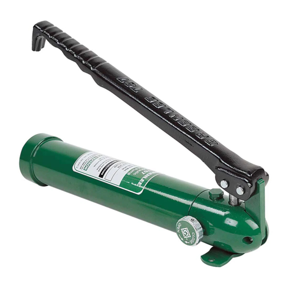
Hydraulic hand pump
Hide thumbs
Also See for 767:
- Instruction manual (8 pages) ,
- Operation, service and parts instruction manual (9 pages)

Related Manuals for Greenlee 767


Summary of Contents for Greenlee 767
- Page 1 INSTRUCTION MANUAL Hydraulic Hand Pump Serial Code ABM Read and understand all of the instructions and safety information in this manual before operating or servicing this tool. 99923440 © 2007 Greenlee Textron inc. IM 1317 REV 7 1/07...
-
Page 2: Table Of Contents
767 Hydraulic Hand Pump Table of Contents Description Description ..............2 The 767 Hydraulic Hand Pump develops 6500 psi (44,818 kPa) at .0823 in (1.3 cm ) per stroke and is Safety ................2 intended to power Greenlee model 746 and model Purpose of this Manual ..........2 15631 single-acting hydraulic rams. These pump/ram combinations are used in the following Greenlee punch Important Safety Information ......... 3 driver and cable cutter kits: Operation ................ 4 Cable Cutter: model 750 Filling the Pump with Oil ..........4 Punch Drivers: model 1731 Ball Seat Repair .............. 5 model 7306 and 7306SB Reassembly ..............5 model 7310 and 7310SB Troubleshooting . -
Page 3: Important Safety Information
767 Hydraulic Hand Pump IMPORTANT SAFETY INFORMATION SAFETY Skin injection hazard: ALERT Oil under pressure easily punctures SYMBOL skin causing serious injury, gangrene or death. If you are injured by escaping oil, seek medical attention immediately. • Hand-tighten all couplers This symbol is used to call your attention to hazards completely before operating the or unsafe practices which could result in an injury or pump. Do not use tools to tighten property damage. The signal word, defined below, the couplers. -
Page 4: Operation
767 Hydraulic Hand Pump Filling the Pump with Oil Operation 1. Clamp the pump into a vise with the machined 1. Remove the dust cap. reservoir end upward. 2. Connect the hose to the punch driver or cable 2. Unscrew machined reservoir (22) from the pump cutter. block (23) and gently remove machined reservoir. Note: Hand-tighten the couplers completely. 3. Inspect rubber bladder (12), bladder plug (14) and Do not use tools. position and condition of O-ring (13). Replace if 3. Twist the release knob (16) to CLOSE. damaged or worn. 4. Pump the lever (1) until the operation is complete. 4. Pour Greenlee hydraulic oil* into the rubber bladder 5. Twist the release knob (16) to OPEN. (12) until oil comes to the top of the plug hole. 6. Disconnect the hose from the punch driver or cable 5. Turn the release knob (16) to OPEN. Pump the lever cutter. Replace all dust caps. -
Page 5: Ball Seat Repair
767 Hydraulic Hand Pump Ball Seat Repair Reassembly Reseating: Reassembly is done in reverse sequence of disassembly. Minor seat imperfections may be corrected by reseating. Use repair kit 50034349 to replace all O-ring seals, balls Use a soft brass rod and hammer to tap the ball against and springs. its seat. Before installing O-rings, lightly coat O-ring seals and bores of the cylinder with clean hydraulic oil. Coat the discharge check spring (5) with a petroleum gel before installation. Fill unit with clean oil and purge air per instructions under the Filling the Pump with Oil section of this manual. Wear safety glasses when striking the brass rod. Re-drilling: Badly worn or damaged seats may be reworked by re-drilling and then re-seating. The pump block is manufactured with seats of 118˚, the standard drill point angle; use standard drills for re-drilling. • To re-drill the 3/16" ball seats (10): Use an “F” drill and a 7/32" diameter reamer • To re-drill the 1/4" ball seat (11): Use a “Q” drill and a 13/64" diameter reamer When drilling; remove a minimum of material to obtain maximum seat life. Reseat the balls before reassembly. “Q” DRILL DISCHARGE CHECK STD. DRILL ACCEPTABLE “F”... -
Page 6: Troubleshooting
767 Hydraulic Hand Pump Troubleshooting Problem Probable Cause Possible Remedy Oil leak at coupler. Fitting loose or damaged. Tighten or replace fitting and/or coupler. O-ring is worn or damaged. Replace O-ring. Pump builds pressure, but ram Coupler is not tightened sufficiently, Hand-tighten coupler completely so does not advance, or ram will and check balls are not engaged. check balls engage. Replace coupler not return. if necessary. Oil leak at OPEN/CLOSE O-ring (18) is worn or damaged. Replace O-ring (18). release knob (16). Release stem (15) is bent. Replace release stem (15) and/or release knob (16). Oil leak at pump plunger (24). O-ring (25) and/or backup ring (27) Replace O-ring (25) and backup (Attached to handle.) are worn or damaged. ring (27). Oil leak at reservoir end. Bladder plug (14) or rubber bladder (12) Replace bladder plug (14) and/or is punctured or worn. rubber bladder (12). O-ring (13) damaged or out of position. Replace or reposition O-ring (13). Can’t hold load or excessive Ball (10) in release knob (16) leaking. -
Page 7: Illustration And Parts List
767 Hydraulic Hand Pump Exploded View SECTION B-B SECTION A-A Greenlee / A Textron Company 4455 Boeing Dr. • Rockford, IL 61109-2988 USA • 815-397-7070... - Page 8 815-397-1865 Canada 800-435-0786 Fax: 800-524-2853 International +1-815-397-7070 Fax: +1-815-397-9247 4455 Boeing Drive • Rockford, IL 61109-2988 • USA • 815-397-7070 An ISO 9001 Company • Greenlee Textron Inc. is a subsidiary of Textron Inc. www.greenlee.com Printed in USA Greenlee / A Textron Company 4455 Boeing Dr. • Rockford, IL 61109-2988 USA • 815-397-7070...