Table of Contents
Advertisement
Quick Links
c
Copyright 2003 The Stanley Works
USA & CE Version
60788 7/2003 Ver. 1
Service Manual
®
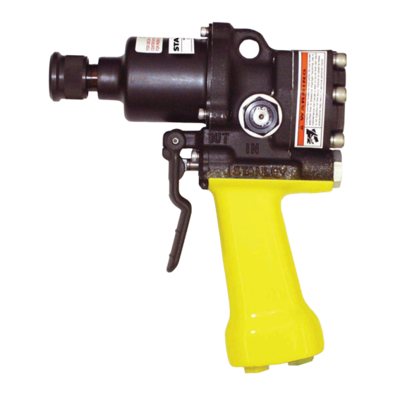
ID07
Impact Drill/
DANGER
SERIOUS INJURY OR DEATH COULD RESULT
FROM THE IMPROPER REPAIR OR SERVICE OF
THIS TOOL.
REPAIRS AND/OR SERVICE TO THIS TOOL
MUST ONLY BE DONE BY AN AUTHORIZED AND
CERTIFIED DEALER.
Wrench
Advertisement
Table of Contents

Related Manuals for Stanley IDO7


Summary of Contents for Stanley IDO7
- Page 1 SERIOUS INJURY OR DEATH COULD RESULT FROM THE IMPROPER REPAIR OR SERVICE OF THIS TOOL. REPAIRS AND/OR SERVICE TO THIS TOOL MUST ONLY BE DONE BY AN AUTHORIZED AND Copyright 2003 The Stanley Works USA & CE Version CERTIFIED DEALER. 60788 7/2003 Ver. 1...
-
Page 2: Table Of Contents
It is the responsibility of the operator and not be copied in whole or in part without service technician to read rules and the prior written consent of The Stanley Works. This exception does not permit instructions for safe and proper operation copies to be made for others, whether or and maintenance. -
Page 3: Certificate Of Conformity
1995 28662-7 1997 Self Special Provisions: None Sound Level: 108 dBA Spezielle Bestimmungen: Vibration Level: 2.0 m/s Dispositions particulières: Provisiones especiales: Misure special: Done at/Ort/Fait à/Dado en/Fatto a Stanley Hydraulic Tools, Milwaukie, Oregon USA Date/Datum/le/Fecha/Data 6/16/03 Signature/Unterschrift/Signature/Firma/Firma Position/Position/Fonction/Puesto/Posizione Engineering Manager... -
Page 4: Specifications
Specifications Drive Size__________1/2 in. square or 7/16 in. hex Motor____________________________ Integral Pressure Range___________ 2000 psi / 140 bar Outport Torque_____________500 ft lbs / 675 Nm Flow Range_____________4-12 gpm / 15-45 lpm Max. Fluid Temp._____________ ° F / 60° C Optimum Flow____________4-9 gpm / 15-34 lpm HTMA Class I ____________4-6 gpm @ 2000 psi Porting_______________________-8 SAE O-ring Connect Size &... -
Page 5: General Safety Instructions
Do not exceed the rated limits of the tool or use the tool for applications beyond its design capacity. Always keep critical tool markings, such as labels and warning stickers legible. Always replace parts with replacement parts recommended by Stanley Hydraulic Tools. -
Page 6: Tool Decals And Tags
A Name Tag Sticker is attached to the tool. Never exceed the flow and pressure levels specified on this sticker.The information listed on the name tag sticker must be legible at all times. Replace this sticker if it becomes worn or damaged. A replacement is available from your local Stanley distributor. -
Page 7: Hydraulic Hose Requirements
HOSE SAFETY TAGS To help ensure your safety, the following DANGER tags are attached to all hoses purchased from Stanley Hydraulic Tools. DO NOT REMOVE THESE TAGS. If the information in a tag is illegible because of wear or damage, replace the tag immediately. A new tag may be obtained at no charge from your Stanley Distributor. -
Page 8: Htma Requirements
HTMA Requirements Tool Category 20Lpm at 138bar 30Lpm at 138bar 40Lpm at 138bar Hydraulic System BHTMA CATEGORY BHTMA CATEGORY EHTMA CATEGORY Requirements Type III Type II Type I Flow rate 7-9 gpm 10.5-11.6 gpm 11-13 gpm Tool Operating Pressure (15-23 lpm) (26-34 lpm) (36-44 lpm) (42-49 lpm) -
Page 9: Operating Instructions
Operating Instructions IMPORTANT: In addition to the GENERAL sockets from 1/2 in. to 1 in. hex. The ID07 provides output torque up to 500 ft lbs/ 675 Nm. See the SAFETY INSTRUCTIONS on pg 5 of this manual, information below on WRENCH TORQUE. observe the following for equipment protection and care. -
Page 10: Connect Hoses
Operating Instructions develops a flow of 4-12 gpm/ 15-45 lpm at end of the valve IN. 2000 psi/ 140 bar. NOTE: To more accurately tighten bolts, lubricate threads and check with a torque wrench. 2. Make certain the hydraulic power source is equipped with a relief valve set to open at Duplicate time of impacting for other bolts of the same length and thread size. - Page 11 Operating Instructions Open Center/ Closed Center Setup (OC/CC) This tool can be configured to run on both open center and closed center systems. Set for proper system before use. 1. Determine system type. 2. Remove hex plug (44) from spring cap using a 3/16 in.
-
Page 12: Service Instructions
Service Instructions 5. To remove a 7/16 inch anvil from the hammer Note: For orientation of parts in the following case, complete the following steps. procedures, refer to the parts drawing later in this manual. a. Using two small screw drivers, push the thrust ring (57) down and pry out the thrust ring lock Prior to Disassembly (58). -
Page 13: Tool Disassembly
Service Instructions (83) and then push the valve spool (65) out of the shown in the parts illustration (one hammer spring cap end of the main housing. Remove the o- appears to be upside down against the other). ring (19) from the main housing and the o-ring (18) The order (front to back) does not matter as long from the valve spool. - Page 14 Service Instructions 5. Install each end cap (72) and secure withretaining shows, replace the bushings. Inspect the motor shaft ring (74). and idler shaft for corresponding wear and replace as 6. Lubricate the seal area of the main shaft (37) and required.
-
Page 15: Troubleshooting
Troubleshooting This section describes how to find and resolve problems users may experience. If a situation occurs that is not covered, call your Stanley Customer Service representative for assistance. WARNING Inspecting the tool or installing parts with the hydraulic hoses connected can result in severe personal injury or equipment damage. -
Page 16: Parts Illustration
ID07 Parts Illustration... -
Page 17: Parts List
ID07 Parts List Description Notes Item Part Qty. O-ring 13/16 X 15/16 X 1/16 -019 ID07920 Only 00012 O-ring 3/16 X 5/16 X 1/16 -008 00026 O-ring 1/2 X 5/8 X 1/16 -014 00175 Lockwasher 5/16" I.D 00231 O-ring 1/2 X 11/16 X 3/32 -112 00354 Dowel Pin 1/4 X 1 00713... -
Page 18: Id07 Parts List
ID07 Parts List Item Description Notes Part Qty. 32151 Retainer ID07820, ID0782001, ID07920 32152 Spring ID07820, ID0782001, ID07920 48987 Valve Spool Selector Screw 48989 49139 Seal Wiper 56721 Relief Cartridge Assy Includes #7, 13 56725 Hose Assy 471st-05-01-08-06-08-18 ID07810S Only 56747 Seal Wiper 56749... -
Page 19: Accessories
Accessories NOTE: Part Part Description Use Part Number 05079 7/16 in. Quick Change Chuck to 1/2 in. Square Female and Description when 05117 Adapter, 7/16 in. Hex Shank to 1/2 in Square Male ordering. 07192 5/8 in. Quick Change Adapter to 1/2 in. Square Female 05080 Adapter, 5/8 in. -
Page 20: Warranty
Stanley Hydraulic Tools (hereinafter called “Stanley”), subject to the exceptions contained below, warrants new hydraulic tools for a period of one year from the date of sale to the first retail purchaser, or for a period of 2 years from the shipping date from Stanley, whichever period expires first, to be free of defects in material and/or workmanship at the time of delivery, and will, at its option, repair or replace any tool or part of a tool, or new part, which is found upon examination by a Stanley authorized service outlet or by Stanley’s factory in Milwaukie, Oregon to be DEFECTIVE IN... - Page 22 For additional Sales & Service information, contact: ® Stanley Hydraulic Tools Division of the Stanley Works 3810 SE Naef Road Milwaukie, OR 97267 USA Tel: (503) 659-5660 Fax: (503) 652-1780 www.stanley-hydraulic-tools.com...