Table of Contents
Troubleshooting

Related Manuals for Invacare R100


Summary of Contents for Invacare R100
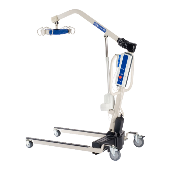
- Page 1 ® Invacare Reliant™ 450 RPL450-2 ® Invacare Reliant 600 RPL600-2 Electric Portable Patient Lift User Manual This manual MUST be given to the user of the product. BEFORE using this product, read this manual and save for future reference.
- Page 2 © 2011 Invacare Corporation. All rights reserved. Republication, duplication or modification in whole or in part is prohibited without prior written permission from Invacare. Trademarks are identified by ™ and ®. All trademarks are owned by or licensed to Invacare Corporation or its subsidiaries unless otherwise noted.
-
Page 3: Table Of Contents
User Manual Electric Portable Patient Lift DEALER: This manual MUST be given to the user of the product. USER: BEFORE using this product, read this manual and save for future reference. GENERAL ASSEMBLY Symbols ......................5 Introduction....................15 Warnings....................5 Unpacking the Patient Lift ..............15 Limited Warranty ..................6 Assembling the Mast to the Base............ - Page 4 CONTENTS TRANSFERRING THE PATIENT ACCESSORIES Introduction ..................... 28 Reliant Scale RLS6 ................... 42 Removing the Swivel Bar..............42 Transferring to a Commode Chair............. 29 Installing the Reliant Scale ............... 44 Transferring to a Standard Commode..........30 Operating the Scale ................46 Transferring to a Bathing Unit .............
-
Page 5: General
1 GENERAL 1 General Symbols Warnings Signal words are used in this manual and apply to hazards or unsafe practices which could result in personal injury or property damage. See the information below for definitions of the signal words. DANGER Danger indicates an imminently hazardous situation which, if not avoided, will result in death or serious injury. -
Page 6: Limited Warranty
This warranty gives you specific legal rights and you may also have other legal rights which vary from state to state. Invacare warrants the products manufactured to be free from defects in materials and workmanship for a period of three years on the lift and one year on the slings and electric components from the date of purchase. -
Page 7: Safety
General WARNING The Invacare patient lift is NOT a transport device. It is intended to transfer an individual from one resting surface to another (such as a bed to a wheelchair). Otherwise injury or damage may occur. DO NOT attempt any transfer without approval of the patient’s physician, nurse or medical assistant. Thoroughly read the instructions in this Owner’s Manual, observe a trained team of experts perform the lifting procedures and then perform the entire lift procedure several... -
Page 8: Pinch Points And Positioning
WARNING Although Invacare recommends that two assistants be used for all lifting preparation, transferring from and transferring to procedures, our equipment will permit proper operation by one assistant. The use of one assistant is based on the evaluation of the health care professional for each individual case. -
Page 9: Using The Sling
Use steering handle on the mast at all times to push or pull the patient lift. Invacare does not recommend locking of the rear casters of the patient lift when lifting an individual. Doing so could cause the lift to tip and endanger the patient and assistants. -
Page 10: Transferring The Patient
2 SAFETY Transferring the Patient WARNING When elevated a few inches off the surface of the stationary object (wheelchair, commode, or bed) and before moving the patient, check again to make sure that the sling is properly connected to the hooks of the swivel bar. If any attachments are not properly in place, lower the patient back onto the stationary object (wheelchair, commode, or bed) and correct this problem. -
Page 11: Electrical And Grounding
GROUNDING INSTRUCTIONS DO NOT, under any circumstances, cut or remove the round grounding prong from any plug used with or for Invacare products. Some devices are equipped with three-prong (grounding) plugs for protection against possible shock hazards. Where a two-prong wall receptacle is encountered, it is the personal responsibility and obligation of the customer to contact a qualified electrician and have the two-prong receptacle replaced with a properly grounded three-prong wall receptacle in accordance with the National Electrical Code. -
Page 12: Product Labeling
Lift, READ and UNDERSTAND the Owner’s Manual for proper operation and safety procedures. WEIGHT LIMITATION 600 lbs. The Invacare Patient lift is NOT a transport device. DO NOT roll casterbase over uneven surfaces that may cause the Patient Lift to tip over. -
Page 13: Technical Data
4 TECHNICAL DATA 4 Technical Data Patient Lift 450 LB. ELECTRIC 600 LB. ELECTRIC LOW PROFILE LOW PROFILE RPL450-2 RPL600-2 Height at Sling Hook-up - MAX.: 74 inches 68 inches Height at Sling Hook-up - MIN.: 24 inches 28 inches Base Width OPEN: 41.0 inches Base Width CLOSED:... -
Page 14: Full Body, Divided Leg And Toileting Slings
FULL BODY FULL BODY DIVIDED LEG TOILETING HEAVY HEAVY W/COMMODE DUTY W/O DUTY W/ COMMODE COMMODE R110 R111 R114 R115 R116 R117* R100P R100 R101 R102 R121 R140* R141* R112* R113* Size: Width: 41.5 45.5 45.5 41.5 45.4 45.5 37.5 44.5... -
Page 15: Assembly
Introduction WARNING Use only Invacare parts in the assembly of this patient lift. The base legs, mast, boom assembly and the swivel bar are manufactured to specifications that assure correct alignment of all parts for safe functional operation. Unpacking the Patient Lift Unpack the components from the shipping carton. -
Page 16: Assembling The Mast To The Base
5 ASSEMBLY Assembling the Mast to the Base WARNING The mast may be removed from the base for storage or transporting. Each time the mast is removed and returned to the base, the mast MUST be properly secured to the base assembly. If locking-type casters are on the patient lift, lock them. -
Page 17: Assembling The Boom Actuator
5 ASSEMBLY Assembling the Boom Actuator CAUTION Washer Shoulder Bolt Boom Assembly Mounting Bracket DO NOT overtighten the nut and bolt. This damages the mounting bracket. Remove the shoulder bolt, washer and nut from the mounting bracket on the boom assembly. Unpack the pinch guard from the patient lift carton. -
Page 18: Installing The Leg Actuator To The Base
5 ASSEMBLY Installing the Leg Actuator to the Base Slide the leg actuator into the slot in the base of the patient lift DETAIL “A” - SIDE VIEW OF PATIENT LIFT (Detail B). Pivot Perform the following to secure the leg actuator to the pivot Bracket Base bracket (Detail A):... -
Page 19: Mounting The Battery Charger
5 ASSEMBLY Mounting the Battery Charger Refer to your local regulations concerning proper mounting procedures. Place the battery charger with mounting bracket on the wall at the desired position. With a pencil, mark the middle hole position. Measure down 6½ inches from the pencil mark and drill one mounting hole. Install the bottom mounting screw until there is an approximate 1/8-inch gap between the screw head and the wall. -
Page 20: Operation
Invacare recommends that two assistants be used for all lifting preparation and transferring to/from procedures; however, the patient lift can be operated with one assistant. The use of one assistant is based on the evaluation of the health care professional for each individual case. -
Page 21: Activating A Mechanical Emergency Release
6 OPERATION Activating a Mechanical Emergency Release Primary Emergency Release Control Box To activate the primary emergency release, insert a pen into the hole labeled “emergency” on the control box of the lift and push down on the boom at the same time. All lift actuators are equipped with a mechanical Emergency release. -
Page 22: Performing An Emergency Stop
6 OPERATION Performing an Emergency Stop Press the RED/ORANGE emergency button on the control box in to stop the boom assembly and patient from raising or lowering. Rotate the RED/ORANGE emergency stop button clockwise to disengage the emergency stop. Rotate CLOCKWISE to Disengage Emergency Stop Control Box Press IN to Stop... -
Page 23: Charging The Battery
6 OPERATION Charging the Battery Invacare recommends the battery be recharged daily to Handle (STEPS 1, 2, 4, and 5) prolong battery life. An audible alarm will sound (horn will beep) when battery is low. Lift up on the handle on the back of the battery. -
Page 24: Lifting The Patient
Invacare recommends that two assistants be used for all lifting preparation and transferring to/from procedures; however, our equipment will permit proper operation by one assistant. The use of one assistant is based on the evaluation of the health care professional for each individual case. -
Page 25: Attaching A Sling
Match the corresponding colors on each side of the sling for an even lift of the patient. Model Nos. R110 - R117 Full Body Slings and Model No. R121 Toileting Sling have four sling straps. Model Nos. R100 - R102 Divided Leg Slings have six sling straps. -
Page 26: Lifting/Moving The Patient
Adjustments for safety and comfort should be made before moving the patient. DO NOT use slings and patient lifts of different manufacturers. Invacare slings are made specifically for use with Invacare patient lifts. Injury or damage may occur. -
Page 27: Electric Portable Patient Lift
7 LIFTING THE PATIENT DETAIL “A” - LIFTING THE PATIENT DETAIL “B” - MOVING THE PATIENT DETAIL “C” - MOVING THE PATIENT LIFT AWAY FROM THE BED FIGURE 7.1 Lifting/Moving the Patient Part No. 1145810 Electric Portable Patient Lift... -
Page 28: Transferring The Patient Introduction
The slings with commode openings are designed to be used with either a commode chair or standard commode. Invacare recommends that the sling remain connected to the swivel bar hooks during the patient’s use of either the commode chair or standard commode. -
Page 29: Transferring To A Commode Chair
8 TRANSFERRING THE PATIENT Transferring to a Commode Chair Lift the patient from the bed. Refer to Lifting the Patient on page 24. Press the boom up button to elevate the patient high enough to clear the arms of the commode chair. Their weight will be supported by the patient lift. -
Page 30: Transferring To A Standard Commode
The Invacare patient lift is NOT intended as a transport device. If the bathroom facilities are NOT near the bed or if the patient lift cannot be easily maneuvered towards the commode, then the patient MUST be transferred to a wheelchair and transported to the bathroom facilities before using the patient lift again to position the patient on a standard commode. -
Page 31: Transferring To A Wheelchair
8 TRANSFERRING THE PATIENT Transferring to a Wheelchair Lift the patient from the bed. Refer to Lifting the Patient on page 26. Ensure the legs of the lift with patient in the sling are in the open position. Press the legs open button until in maximum open position. -
Page 32: Troubleshooting
Refer to Checking and Tightening Mast Pivot Bolt on page 37. power retraction. and mast may not be properly installed. If problems are not remedied by the suggested means, please contact your dealer or Invacare. Electric Portable Patient Lift Part No. 1145810... -
Page 33: Maintenance
10 MAINTENANCE 10 Maintenance 10.1 Maintenance Safety Inspection Checklist For individual home use, a full inspection is required prior to each new user. Regular cleaning will reveal loose or worn parts, enhance smooth operation and extend the life expectancy of the lift. Follow the maintenance procedures described in this manual to keep your patient lift in continuous service. - Page 34 10 MAINTENANCE INSTITUTIONAL IN-HOME INSPECT INSPECT/ADJUST EVERY SIX (6) ITEM INITIALLY MONTHLY MONTHS THE BOOM Check all hardware and swivel bar supports. Inspect for bends or deflections. Inspect bolted joints of boom for wear. Inspect to ensure that the boom is centered between the base legs. Check the mast pivot bolt under the rubber boot.
-
Page 35: Lubricating The Lift
10 MAINTENANCE The Invacare Patient Lift is designed to provide a maximum of safe, efficient and satisfactory service with minimum care and maintenance. All parts of the Patient Lift are made of the best grades of steel, but metal to metal contact will wear after considerable use. -
Page 36: Detecting Wear And Damage
10 MAINTENANCE 10.3 Detecting Wear and Damage It is important to inspect all stressed parts, such as slings, spreader bar and any pivot for slings for signs of cracking, fraying, deformation or deterioration. Replace any defective parts immediately and ensure that the lift is not used until repairs are made. 10.4 Cleaning the Sling and the Lift The sling should be regularly washed in water, temperature not to exceed 180°F (82°C) and a biocidal (anti-biological) solution. -
Page 37: Checking And Tightening Mast Pivot Bolt
10 MAINTENANCE 10.6 Checking and Tightening Mast Pivot Bolt Lift up the back of the rubber boot and slide it off the mast along Rubber Boot Washer the boom. Boom Check that the bolt is through the bracket and the locknut is tight Bolt and secure. -
Page 38: Replacing The Swivel Bar
10 MAINTENANCE 10.7 Replacing the Swivel Bar WARNING After the first year of use, the hooks of the swivel bar and mounting brackets of the boom should be inspected every six months to determine the extent of wear. If these parts become worn, replacement must be made. The swivel bar comes attached to the boom with bolt, nut, washers, and pinch guard. -
Page 39: Maintaining The Base Adjustment
10 MAINTENANCE 10.8 Maintaining the Base Adjustment Square Linkage Rods The base adjustment should not require any attention other than: Check that the legs are square when in the closed position. Place a square on the inside of the legs and base to determine the 90°... -
Page 40: Replacing Casters/Forks
10 MAINTENANCE 10.9 Replacing Casters/Forks WARNING Ensure that there is sufficient room to turn patient lift on its side and that floor area is clear of debris. Otherwise, injury to personnel or damage to patient lift may occur. Replacing Rear Casters Base Place the lift on its side. -
Page 41: Replacing Front Casters
10 MAINTENANCE Replacing Front Casters Place the lift on its side. Base Remove the bolt and locknut that secure the existing front caster assembly to the fork. The front caster assembly consists of two casters and a Fork washer in between. The washer will fall out from between the two casters. -
Page 42: Accessories
11 Accessories 11.1 Reliant Scale RLS6 The Reliant Scale is a compact precision scale system designed specifically for the Invacare Patient Lift System. WARNING DO NOT install or use this equipment without first reading and understanding these instructions. If you are unable to understand the Warnings, Cautions or Instructions, contact a healthcare professional, dealer or technical personnel before attempting to install this equipment - otherwise, injury or damage may occur. - Page 43 11 ACCESSORIES Boom Boom Mounting Bracket Locknut (Save for installing Scale) Washer (Save for installing scale) Pinch Guard Shoulder Bolt (Save for installing scale) *450 lb Swivel Bar Swivel Bar Pin Nylon Washers *600 lift swivel bar not shown. FIGURE 11.1 Removing the Swivel Bar Part No.
-
Page 44: Installing The Reliant Scale
11 ACCESSORIES Installing the Reliant Scale For this procedure, refer to FIGURE 11.2. WARNING Patient and sling MUST be removed from the lift during ALL installation procedures. Position the load cell assembly of the Reliant Scale into the boom mounting bracket. Refer to Detail “A” in FIGURE 11.2. ... - Page 45 11 ACCESSORIES DETAIL “A” Reliant DETAIL “B” Boom Scale Locknut Mounting Screw Boom Mounting Bracket Locknut Shoulder Swivel Bar Nylon Bolt Washer Nylon Nylon Washers Reliant Washer Scale Load Cell Swivel Bar Pin Assembly FIGURE 11.2 Installing the Reliant Scale Part No. 1145810 Electric Portable Patient Lift...
-
Page 46: Operating The Scale
11 ACCESSORIES 11.2 Operating the Scale Keypad Functions INDICATOR INDICATOR DISPLAYED LOCATION DEFINITION Center of Display Window Pressing this key will apply power to the scale and turn the unit on. When the scale is already on, pressing the button will turn the unit off. ZERO ZERO Lower Left Corner of the Display Window... -
Page 47: Weighing The Patient
11 ACCESSORIES 11.3 Weighing the Patient WARNING The weight capacity is limited to the lowest rated capacity of any one of the components in use (e.g. Patient Lift, Sling or Scale). The patient's weight MUST not exceed the lowest rated capacity of any component. DO NOT operate key strokes with pointed objects (e.g. -
Page 48: Replacing The Battery
11 ACCESSORIES Should it be necessary to unlock the weight while the patient is still supported by the lift, the UNLOCK button may be pressed. The weight will unlock and the word “LOCK” will disappear from the display window. The weight value will then be updated. Once the weight becomes stable the weight can be locked again by pressing the LOCK button. -
Page 49: Calibrating The Reliant Scale
11 ACCESSORIES Calibrating the Reliant Scale The Reliant Scale will be pre-calibrated at the factory with the load cell. Should it be necessary to re-calibrate the scale, follow the instructions outlined below. The patient and the sling must be removed from the scale to properly calibrate the Reliant Scale. For removing the patient instructions refer to Operation on page 20. -
Page 50: Troubleshooting
Unit does NOT work properly. Battery failure. Check battery. Replace if necessary. Battery has been replaced and unit still does Contact Invacare for Service at 1-800-333-6900 NOT work properly. Display Codes CALIBRATION REQUIRED - Indicates improper stored calibration data, calibration is necessary. - Page 51 NOTES Notes Part No. 1145810 Electric Portable Patient Lift...
- Page 52 Invacare Corporation Canada One Invacare Way 570 Matheson Blvd E Unit 8 Elyria, Ohio USA Mississauga Ontario 44036-2125 L4Z 4G4 Canada 800-333-6900 800-668-5324 Part No. 1145810 Rev B - 05/11 www.invacare.com...